Note: Descriptions are shown in the official language in which they were submitted.
CA 02177097 2004-03-22
2
REMOTE CONTROLLED MIRROR SYSTEM FOR VEHICLES
This invention relates to a remote controlled mirror system for vehicles,
particularly for trucks and articulated vehicles, where it is necessary to
have a view to the
rear of the vehicle over a wide angle field which cannot satisfactorily be
achieved by use
of a fixed mirror.
Instances where wider angle view is necessary occur whenever the vehicle is
being
manoeuvred in a parking or loading or unloading situation, when it is being
driven in tight
surroundings or in narrow thoroughfare conditions and when it is entering,
changing or
exiting lanes on a highway. Other instances occur and there is no attempt in
this
description to limit use of the device to those particular situations just
described.
In the past, wide mirror viewing has been approached by making the mirror
deflectable within its mounting. In one type of system the mirror is
controlled by the
angulation between vehicles having a cab and trailer for instance, U.S. Patent
4,609,265,
U.S. 5,056,905, or U.S. 5,249,083. In another, Canadian Patent 2,084,895, a
timer
mechanism determines the extent of mirror deflection.
Problems arise in all instances in acquiring adequate driver control of the
position
of the mirror and in resetting it to its "straight ahead" position after it
has been deflected
for wide angle viewing of the surroundings of the vehicle.
To overcome previous difficulties of accurate and smooth control of the
positioning of the mirror by the driver when using the mirror to sweep or
examine areas of
the surrounding to the vehicle, and to allow the mirror to regain accurately
its undeflected
straight ahead position after use, the present disclosure provides a mirror
deflecting system
comprising: a mirror; means mounting the mirror for movement about a mirror
axis so that
field of view through the mirror can be changed, from that when in a rest
position of the
mirror, upon its said movement; a lever arm mounted for movement between a
rest
position and a deflected position; means for urging said lever arm into its
rest position
whenever moved from that position; operative means connecting said lever arm
and said
mirror for effecting movement of said mirror about said axis when said lever
arm is
deflected from said rest position; means for setting the rest position of said
mirror; and
means for locking said lever arm in multiple deflected positions out of said
rest position of
said lever arm.
The invention allows not only trucks, but buses and vans, and any large
vehicle to
be improved for safety, ease of driving and manoeuvring and the removing of
blind spots,
CA 02177097 2004-03-22
particularly the right side blind area in those vehicles having left hand
drive (left side blind
area for those having right hand drive).
Electrically rotated mirrors are now commonplace in vehicles, and the
motorising
allows for the sweeping of the mirror transversely and in azimuth.
This standard arrangement is not satisfactory for the situations envisaged
above. The
motor movement is invariably too slow for most purposes and does not allow for
automatic resetting of the mirror to the straight ahead position.
This disclosure also provides a mirror deflecting system comprising: a mirror;
means mounting the mirror for movement about a mirror axis so that field of
view through
the mirror can be changed, from that in a rest position of the mirror, upon
its said
movement; a lever arm mounted for movement between a rest position and a
deflected
position; means for urging said lever arm into its rest position whenever
moved from that
position; operative means connecting said lever arm and said mirror for
effecting
movement of said mirror about said axis when said lever arm is deflected from
said rest
position; means for setting the rest position of said mirror; wherein the
operative means
comprises a reversible motor connected to said mirror for moving it about its
mirror axis,
means sensing the position of said lever arm, means connecting said motor and
said means
sensing the position of said lever arm for driving said motor in a direction
corresponding
to direction of movement of said lever arm, second sensing means for sensing
position of
said mirror about said axis, feed back means to said motor from said second
sensing
means for terminating operation of said motor when the mirror has been moved
to a
position corresponding to sensed position of said lever arm; and variable
potential
adjusting means connected to said second sensing means for setting shaft
position of said
motor with respect to the position of said lever arm for allowing rest
position adjustment
of said mirror.
Embodiments of the present invention will now be described with reference to
the
accompanying drawings wherein:
Figure 1 shows a plan view in diagrammatic form of an articulated truck with
the
usual side mounted mirrors, and which shows the lines of sight for the driver
and the blind
area generated;
Figure 2 is a plan view similar to Figure 1, but with the vehicle making a
left hand
turn into a traffic pattern;
CA 02177097 2004-03-22
3a
Figure 3 is a view similar to Figures 1 and 2, but with the vehicle making a
right
hand turn from an outer lane in multi lane traffic;
Figure 4 diagrammatically shows a front elevation of a typical mirror mount
for a
truck;
Figures SA1 and SA2 show a side and plan view respectively of the upper mirror
mount;
Figures SB1 and SB2 are the same views as Figures SA1 and SA2, but applicable
to one embodiment of the invention;
Figure 6 is a side view of the lower mount and swivel mechanism for a mirror
structure embodying the invention;
Figure 7 shows a side view of the mounted installed mirror of an embodiment of
the invention;
Figure 8 shows a side view of a typical hand grip arrangement by which the
driver
can control the positioning of the mirror at any time;
Figure 9 is a side view, partly in section, of part of a modified hand grip
21 ll fl9?
4
arrangement with locking means;
Figure 10 is a side view at right angles to that of Figure 9;
Figure 11A is a sectional view of a bistable push-push arrangement for
latching the
ratchet of Figures 9 and 10 in unlatched position;
Figure 11B is the same arrangement of Figure 11A in latched position;
Figure 12 is a diagrammatic circuit diagram used in the second inventive
embodiment of the mirror positioning system; and
Figure 13 is a circuit diagram of another inventive embodiment.
With reference first to Figure 1, a driver 1 in an articulated vehicle
assembly 2,
having left hand drive, includes a cab 3 and trailer 4. The cab has the
conventional
outside cab mounted left rear view mirror 6 and right rear view mirror 7. As
is typical in
this and many similar large vehicles, the driver's direct view through the
window at the
back of the cab is blocked by the trailer so that all rear view is through
these outside
mirrors. The driver's direct angle of view is slightly greater than
180° since he can look
over his left shoulder through the left door window, through the windshield,
and through
the right door window. The rear view mirrors supplement this. These mirrors
have been
developed over the years from a small mirror on one arm on one side which was
subject
to vibration, to currently, two large mirrors which can be six inches wide and
sixteen
inches high. One very popular system has the mirrors braced to the door or to
the cab by
at least five adjustable arms, and known in the industry as "West Coast"
mirrors. They are
mounted out far enough from the cab to allow the driver to look back along the
side of the
trailer box as indicated by the sight lines 10 on the left and 11 on the right
as he moves
his head forward or back or leans while in the seat.
On the right side there is a blind area between the driver's direct view and
the area
covered by the right mirror, embraced by sight lines 12 and 13. The mirror 7
can be
convex to minimize the size of the blind area 14, but this reduces the size of
the objects
with the consequent reducing benefit to the driver. The problem created by the
blind area
14 when entering traffic is exemplified in Figure 2 when the combination of
leaning
forward and looking to the right increases the likelihood of surprises,
particularly those
coming out of the blind area which prevents the driver seeing oncoming traffic
from the
right. As shown in Figure 3, a very similar problem can arise when turning
across lanes
in traffic where the blind area 14 blocks the driver's view of the upcoming
vehicle 15 with
. y
obviously dangerous consequences. There is a blind area 21 on the left side
behind the
sight line 22 which develops when the vehicle is in the position of Figure 3.
Though this
is not a problem in the particular situation depicted in Figure 3, it becomes
significant
when parking or manoeuvring the vehicle at a busy loading dock with traffic
moving
around or past the dock.
As Figure 4 depicts, a typical mirror 31 is attached to the upper arm 32 of a
mounting bracket 30 by a threaded axle 34 whose end is received in slot 36 of
arm 32 (see
Figures SA1 and SA2) and tightened with a washer and nut assembly 33 and 35 on
either
side of the arm 32. This attaches the upper part of the mirror to the mount,
secures it
against vibration and allows it to be adjusted in the horizontal plane by
rotating on the
axle 34. The mirror is similarly mounted at its lower end by axle 35 in lower
arm 58. If
need be, it can also be moved vertically in the slot 36.
The inventor has discovered that if the mirror can be made horizontally
rotating
under the control of the driver, it is possible to sweep or pan the blind area
concerned so
that it can be eliminated, when and only when required, without losing normal
viewing at
other times.
To this end the mirror concerned can be made rotatable about its vertical
mounting
axis. As Figures SB 1 and SB2 show, a modification to the upper point where
the mirror is
secured to the bracket 32 allows this by inserting a bushing 40 into the slot
36 of the
bracket 32. The bushing is externally threaded and it can be secured in the
slot 36 with
nut 44 and 47. The mirror axle 34, is received in bushing 40, and is free to
rotate within
it.
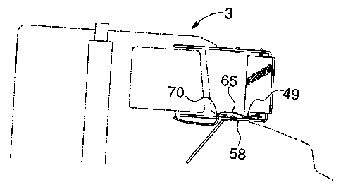
With reference to Figure 6, at the lower side of the mirror the mounting
assembly
is modified so that the lower mounting shaft 35 is free to turn but is spring
loaded to
rotate to a fixed or rest position whenever deflected out of this rest
position by movement
of a control arm 49. The lower shaft 35 of the mirror has nut 50, and fibre
washer 52
placed upon it, which engages against the head of bushing 54 (similar to
bushing 40) and
which itself is threaded to nut 56 against the lower arm 58 (see Figure 4) of
the mounting
bracket. Not seen in the view of Figure 6 and beneath a return spring 60 is
the lower part
of the bushing 54 (similar to bushing 40 and carrying a nut similar to nut
42). The shaft
35 is flattened on the side of its lower end, so that a control arm 49 having
a cooperating
shoulder segment can be placed on the shaft and secured against rotation with
respect to
21~770~7
6
the shaft to allow the arm to twist the shaft about its axis. A nut 62 secures
the arm 49 on
the shaft and the return spring action between the bracket 58 and arm 49 urges
the shaft to
rotate in the direction of relaxation of the spring. In the arrangement shown
the spring is
such that it rotates the mirror in the anti-clockwise direction. An adjustable
stop for the
arm (not shown) can be provided for aligning for the "straight ahead" rest
position for the
mirror.
A positioning mechanism for the control arm 49 comprises a Bowden type
cable 65, wherein the inner core can slide longitudinally with respect to the
outer and
which is illustrated in Figure 7, the outer part of the cable being clamped to
the bracket 58
at the point 70 and the inner core being fastened to the end of the control
arm. This
allows a straight pull or push on the end of the control arm with respect to
the clamping
point 70 when the inner flexible core of the cable is moved with respect to
the outer. The
extent of the movement of the inner core is directly related to the amount of
turning to be
effected in the mirror about its axis. As illustrated in Figure 7, as the
inner core moves
into the outer jacket, so the mirror will rotate in the plane of the paper,
that is in a
clockwise direction with respect to a driver in the illustrated cab 3.
A suitable mechanism for moving the inner core of the cable with respect to
the
outer and which forms a control grip for the driver, is illustrated at 89 in
Figure 8. This is
similar to a handlebar brake grip for a bicycle or motorcycle which includes a
lever arm
90 pivoted at 91 in a frame portion 92. The frame 92 carries a stem 93 and the
frame is
also adjustably fastened by bolting through hole 87 to a clamp 86 attached for
instance to
gear shift lever 85 of the vehicle. The inner member 94 of the other end of
the cable 65
(from that end shown in Figure 7) is attached in conventional fashion such as
by means of
a crimped bead 96 on cable 94 received within a spherical recess 97 in the
handle 90. By
grasping this device 89 with the hand between stem 93 and arm 90 the operator
is able to
pull the core or inner section 94 with respect to the cable outer section 98
(received
against the adjustment screw sleeve 88 threaded in flange arm 99 of frame 92).
This
linear movement of inner section 94 with respect to outer section 98 is
transmitted along
the cable to move the lever arm 49 as has been illustrated in Figure 7. By
locating the
unit 89 on the gear shift lever the mirror can be manipulated at the same time
as gear
shifting if necessary. The rest position of the mirror can be adjusted from
within the cab
by turning the threaded sleeve 88.
. 21,71097
7
Particular advantages of the inventive arrangement just described are that the
portion of the mirror is under control of the driver at all times, its
response to activating of
the grip mechanism is instantaneous and is continuously variable between
"straight ahead"
and angle of deflection right up to full deflection. Its return to the rest
position is
immediate when the driver relinquishes his grip, and the rest position is
adjustable right at
the site of the control mechanism to suit the particular operator. Although
the lower arm
49 and spring 60 have been described as being at the lower mirror mount in the
bracket
30, it will be clear to those skilled in the art that the upper and lower
mounting assemblies
could be reversed in any instance thought desirable so that the lever arm 49
is on the
upper shaft 34 of the mirror. The spring 60 may be on the upper mounting
assembly with
the lever arm on the lower assembly by modifications which will also be clear
to the
skilled person. In all these cases, the mirror would be urged by the spring in
the direction
towards its rest position when not activated by the driver through control
grip 89.
While mounting of the control grip 89 on the gear shift is preferred for
convenience of operation, other suitable positions could be below the dash, on
the front of
the dash, on top of the dash, on a hand brake lever, etc.
If it is considered desirable that the mirror should be able to be maintained
in any
particular deflected position when the driver is not holding the lever 90, a
mechanism such
as that illustrated in Figures 9 and 10 can be employed. In Figure 10, the
lever arm 90 is
shown pivoted on an axle 100 carried in hole 91 in frame 92. A serrated or
toothed wheel
102 and a second serrated wheel 102', identical to wheel 102, are fixed to the
lever 90 and
surround the axle 100, and are free to rotate on the axle 100 with the lever
arm 90.
Received within the stem 93 is a spring and plunger housing 105 containing a
plunger 107
urged by spring 109 in the direction from the closed end 110 of the housing to
its open
end 112. The plunger 107 is a sliding fit in the housing and includes two
downwardly
depending legs 114 and 114' which are also serrated on their lower ends to
match and
embrace the serrations of the wheels 102 and 102' respectively over a portion
of their
circumferences. The housing 105 can be moved between the solid position shown
in
Figure 9 and 10 and a raised position shown in broken lines at 120 under the
action of a
longitudinally movable rod 122 which is secured to the closed end face 110 of
the housing
105.
The plunger 107 carries two outwardly extending ears 124 and 124' which run in
2 ~ mo9~
8
longitudinal slots 126 and 126' in the housing 105. In Figures 9 and 10 the
rod 122 is
shown in its down position and the spring 109 urges plunger 107 into engaged
contact
with the wheels 102 and 102'. When rod 122 is subsequently moved to its upper
position
so that the housing 105 occupies the state indicated by broken lines 120 the
raising of the
housing will cause the plunger 107 to have its ears 124 and 124' in contact
with the
lowermost end walls 130 and 130' of the slots 126 and 126'. This lifts the
plunger clear
of the wheels 102 and 102' so that its legs 114 and 114' occupy the position
shown by
broken lines 132 and 132'. In this position lever 90 is free to rotate about
its axle 100
whereas in the down position of the rod it is restrained against rotation by
engagement of
plunger 107 with wheels 102 and 102'. This arrangement has the advantage that,
even
when in the holding or down position of rod 122, the plunger 107 is spring
loaded and
lever 90 can be forced by the operator, when necessary, with a clicking or
ratchet action.
A spring 111 surrounds axle 100 and acts in the sense to urge and return wheel
102' and
thus arm 90 to its rest position.
The number of positions in which the lever arm 90 can be held is to some
extent a
matter of choice. However, typically 10 locked positions over its full range
would be
satisfactory. The number of teeth on the serrated wheels and on the engaging
legs of the
plunger would be determined accordingly.
The flip-flop or two-position movement for rod 122 can be effected in a number
of
ways using a bi-stable mechanism such as that which is commonly employed for
extending
pens or writing instruments where one push extends the instrument and the
second push
releases it. Other mechanisms could include a spring loaded detent ball which
engages rod
122 to hold it in its down position and to lock it there until the ball is
released. In some
instances, a single push push action button would be more convenient, in
others a first
button for moving the rod into the down position coupled with a second for
locking and
unlocking the detent would be preferred. A spring 133 urges the rod 122 into
its upper
position when not held by the detent.
One bi-stable push-push mechanism is illustrated in Figures 11A and 11B. The
rod
122 rests against the base of a flanged triangular detent 135 contained within
a tube such
as the hollow stem 93 discussed earlier and which has offset ridges 136 and
137. In the
position of Figure 10A, the rod 122 is in its uppermost position with flange
138 engaging
against offset 136 and with the side 140 of its head resting against the wall
141 of stem
2 ~ ~.~09~
9
93. Rod 122 is urged upwards by means of spring 133 described earlier and not
shown in
Figure 10A. The press-press release button 142 is prevented from being pulled
out of
stem 93 such as by complementary ears 143 formed on the stem 93 and on the
button 142.
If the button 142 is now pressed in the direction of the arrow 144 the detent
135 will
move downwards along with the rod 122 against the pressure of the spring 133
with head
part 140 riding against the wall 141 and flange 145 sliding against wall 146.
When flange
145 falls below offset 137 an unstable condition is created by virtue of
couple produced by
the line of action of the force on the tip of the head 148 and that on the
base of the detent
135 from the rod 122. The result is that the detent moves sideways to the
right as shown
in Figure l0A so that the flange 145 becomes accommodated beneath offset 137.
When
the pressure of button 142 on head 148 is released slightly, the detent 135
immediately
clicks into the position shown in Figure lOB (by virtue of the couple due to
the force on it
at offset 145 and rod 122) with the side 147 of the head of the detent against
the wall 149.
This is the stable down condition of the detent with rod 122 in the position
in which it is
shown in Figures 9 and 10.
If now pressure is once again exerted downwards on the head 148 of the cone
from
the button 142 as shown in Figure IOB, the opposite unstable condition from
that
considered with respect to Figure l0A occurs. The detent 135 rocks so that
flange 145
moves away from offset 137 until flange 138 rests against the wall 150.
Release of
pressure on the button 142 allows the detent 135 to rise up in the stem 93
until flange 138
contacts against the underside of offset 136. Further release of the pressure
on 142 allows
the top of the detent then to rock across under the couple exerted by the
force from the
offset 136 and that from the rod 122 until the detent 135 takes the position
of Figure l0A
once again. This is the up or released position of the rod 122 and of plunger
107.
Figure 11 is a circuit diagram depicting an embodiment of the invention in
which
the mirror is under the control of a reversible DC motor 200.
The mounting mechanism for the mirror 31 is similar to that earlier described
but
with the motor and associated reduction gearing unit being mounted at the
lower end of
the mirror with its output shaft attached to shaft 35 which is free to move in
a bushing
assembly similar to that described in Figure SB1 and SB2 for upper shaft 34.
As an
alternative the motor and reduction gearing unit can be placed in a housing
within which
the mirror is enclosed for rotation about a vertical axis. The housing can be
permanently
21 X7097
secured to the bracket 32. In this instance the motor and gearing assembly may
be
accommodated behind the mirror within the housing, and the housing is then
shaped
accordingly such as by giving it a smooth bulge area for smooth streamlined
air flow over
it.
As seen in the circuit diagram, the motor gearing output shaft 202 drives both
the
mirror shaft 35 and also the slider 204 of a potentiometer 206, preferably
contained within
the motor or its driven gear housing. Handle 90 of the operator's grip
assembly, instead
of its connection to cable 98 in Figure 8 is now arranged to rotate the slider
208 of a
potentiometer 210 mounted, for instance, on stem 93 in the position shown in
broken lines
at 210 in Figure 10. The shaft 100 in this instance can be fixed to the arm 90
so that it
rotates within the frame 92 and can then be used at the drive for the slider
arm of the
potentiometer 210. A further potentiometer 212 with slider 214 (shown in
Figure 11), can
be mounted on the frame 92 in the broken-line position shown at 212 in Figure
8. A knob
214' connected to the slider 214 is thereby accessible to the driver to allow
the slider to be
moved.
The function of the circuit of Figure 11 is as follows:
The 12V DC supply from the vehicle battery system is applied between terminals
215 and 216. In the instance shown, 216 is the negative rail and connected to
the vehicle
ground. Reversible DC motor 200 is chosen to operate on as low a voltage as
possible
between its two input terminals 220 and 221. Assume that in the position shown
there in
no voltage across the motor terminals, that is that the potentials on sliders
204 and 208 are
identical with respect to ground. If now the handle 90 is moved in the
direction which
raises the potential on the slider 208, current will flow from slider 208
through terminals
220 and 221 of the motor and out through slider 204. This current flow causes
the motor
to rotate, moving shaft 35 or mirror 31 and also moving slider 204 in a
direction to
increase the potential on that slider. The motor will come to rest when no
potential
difference again exists between sliders 208 and 204. Further movement of
handle 90 in
the same direction causes further movement of the motor, and movement of
handle 90 in
the opposite direction reverses the motor and hence the movement of the
mirror. A zero
or rest position setting for the mirror is when the handle 90 is in the
relaxed position (say
with slider 208 close to the lower end of potentiometer 210). This rest
position can be
adjusted using the variable resistance constituted by the potentiometer 212
and slider 214.
217l0 9'7
11
Increasing the resistance decreases the positive voltage on terminal 224 of
potentiometer
206, thus causing the motor to move slider 204 in a direction to compensate
for the
voltage change occasioned by the increase in resistance. Similarly, decreasing
the
resistance of potentiometer 212 raises the potential on slider 204 and causes
the motor to
move in the direction to reduce this potential.
A more sensitive version of this electromechanical drive is available using
the
circuit of Figure 12. In this circuit the sliders 304, 308 and 314 correspond
to sliders 204,
208 and 214 of potentiometer 306, 310 and 312 which in turn correspond to
respective
potentiometers 206, 210 and 212 of Figure 11. An operational amplifier 315 has
its direct
input 323 connected to slider 308. Its output feeds the motor 300 at terminal
320. The
terminal 321 of the motor is connected to a stabilized potential equal or
close to that found
on slider 308 when it is at the mid point of its travel on potentiometer 310.
The stabilized
potential is provided by the source/sink circuit of transistor 330, zener
diode 331 and
resistor 332, or functional equivalent. Slider 304 of the motor position
potentiometer 306
is connected to the inverting input of the OP AMP 315. Potentiometer 306
receives its
input through the variable resistance comprising potentiometer 312 and slider
214.
Let us assume initially that in the position shown the voltage on slider 308
is
identical to that on slider 304, and that the mirror is in some position
between its rest
position and its fully deflected position. If the handle 90 is now moved in a
direction to
increase the mirror deflection and increase the potential on slider 308 there
will be an
increase in potential at the input 323 of amplifier 315, which is translated
to a current
output available to input terminal 320 of motor 300. This causes the motor to
turn in the
direction to increase the mirror deflection. This movement also moves slider
309 in the
direction to increase the potential on it and which appears at inverting input
324 tending to
reduce the output of the amplifier 315. This is a very sensitive feedback loop
which
ensures that very minor changes of voltage on input 323 will lead to
corresponding minor
movements of motor 300 so that it faithfully follows even small changes in
position of
handle 90. Zero positioning of the mirror when the handle is in the released
position (and
the sliders 308 and 304 are near the bottom of their travel on their
respective
potentiometers) can be advanced by varying the position of slider 314 which
transmits
additional or lesser voltage to the upper terminal of potentiometer 306. The
motor moves
in the direction to compensate for this voltage change.
2 ~ l ?Q 97
12
The exact gain of the amplifier is not critical, although it should be
sufficient that
the motor follows all movements of the handle 90 perceptible by the driver.
The
particular voltages given are not critical so long as those available across
the motor
terminals can achieve positive and negative current flow of sufficient
magnitude to turn
the motor effectively.
Because the arm 90 is biased by spring 111 to its rest position, the mirror
will
always be returned to its straight-ahead orientation immediately the operator
releases the
hand grip and at the maximum rate of rotation of the motor. Individual zeroing
is
provided on the hand grip for adjustment to suit the driver concerned.
Other means for generating the potential to be supplied by the positioning of
the
arm 90 to the amplifier 315 will suggest itself to those skilled in the art,
such as a piezo
electric source receiving pressure in accordance with the degree of rotation
of the arm on
its pivot 100. Optic and digital sensors can also be employed to generate the
requisite
voltage signal for supply to the amplifier.