Language selection

Search

Patent 2177522 Summary

Third-party information liability

Some of the information on this Web page has been provided by external sources. The Government of Canada is not responsible for the accuracy, reliability or currency of the information supplied by external sources. Users wishing to rely upon this information should consult directly with the source of the information. Content provided by external sources is not subject to official languages, privacy and accessibility requirements.

Claims and Abstract availability

Any discrepancies in the text and image of the Claims and Abstract are due to differing posting times. Text of the Claims and Abstract are posted:

  • At the time the application is open to public inspection;
  • At the time of issue of the patent (grant).
(12) Patent Application: (11) CA 2177522
(54) English Title: HEATING PANEL FOR MAKING OVENS FOR THERMOFORMING APPARATUS
(54) French Title: PANNEAU CHAUFFANT ENTRANT DANS LA FABRICATION DE FOURS UTILISES EN THERMOFORMAGE
Status: Deemed Abandoned and Beyond the Period of Reinstatement - Pending Response to Notice of Disregarded Communication
Bibliographic Data
(51) International Patent Classification (IPC):
  • B29C 51/42 (2006.01)
  • H05B 03/08 (2006.01)
  • H05B 03/22 (2006.01)
(72) Inventors :
  • DE NICHILO, GIORGIO (Italy)
(73) Owners :
  • GAM IMPIANTI S.A.
(71) Applicants :
  • GAM IMPIANTI S.A. (Switzerland)
(74) Agent: FINLAYSON & SINGLEHURST
(74) Associate agent:
(45) Issued:
(22) Filed Date: 1996-05-28
(41) Open to Public Inspection: 1997-09-28
Examination requested: 2001-02-06
Availability of licence: N/A
Dedicated to the Public: N/A
(25) Language of filing: English

Patent Cooperation Treaty (PCT): No

(30) Application Priority Data:
Application No. Country/Territory Date
MI96A-00608 (Italy) 1996-03-27

Abstracts

English Abstract


An improved construction panel, in
particular for ovens to be used in heating stations
of thermoforming apparatus, comprises two separated
portions, that is: a front portion (2) provided
with heating elements; and a rear portion (3)
holding the related power supply electric cables.
The panel allows to reduce the thermal losses
toward the rear of the construction thereof, so as
to prevent the electric cables from being
overheated and so as to prevent damages to the
maintenance operators.


French Abstract

Panneau de construction amélioré, destiné en particulier aux fours utilisés dans les stations de chauffage des appareils de thermoformage. Il est constitué de deux sections séparées : une section antérieure (2) comportant des éléments de chauffage; et une section postérieure (3) servant à soutenir les câbles d'alimentation électrique associés. Ce panneau permet de réduire les pertes thermiques vers l'arrière de sa structure, pour empêcher la surchauffe des câbles électriques et éviter que les employés chargés de l'entretien ne subissent de ce fait des accidents.

Claims

Note: Claims are shown in the official language in which they were submitted.

THE EMBODIMENTS OF THE INVENTION IN WHICH AN EXCLUSIVE
PROPERTY OR PRIVILEGE IS CLAIMED ARE DEFINED AS FOLLOWS:
1. An improved construction heating
panel, in particular for making ovens to be used in
thermoforming apparatus heating stations, of the
type provided with a surface including a plurality
of heating elements facing a plastic material to be
heated, characterized in that said panel has a
structure constituted by two separated portions,
that is:
- a front portion (2), i.e. facing the plastic
material to be heated, including said heating
elements; and
- a rear portion (3), i.e. facing the side
opposite to that of said front portion (2), holding
the electric power supply cables for power
supplying said heating elements.
2. A panel according to Claim 1,
characterized in that said panel comprises a gap
(11) on a portion thereof connecting said front and
rear portions thereof.
3. A panel according to Claim 2,
characterized in that in said gap 11 is arranged a
thermally insulating material (9).
4. A panel according to Claim 1,
characterized in that said rear portion (3)

11
comprises a box-like element in the inside of which
are provided clamps (5) for connecting said heating
elements to the electric mains.
5. A panel, according to Claim 2,
characterized in that said panels further comprises
screws (7) for connecting said front and rear
portions, a spacer sleeve (10) being provided on
said screws for holding separated said portions (2)
and (3).
6. A panel according to Claim 5,
characterized in that said panel comprises moreover
thermally insulating material inserts (9) arranged
between the engagement surfaces of said screws (7)
and said portions (2) and (3) of said panel (1).
7. A panel according to Claim 1,
characterized in that said front portion (2) is
provided with a fretted surface having raised
portions (2) on which are connected said heating
elements.
8. A panel according to Claim 7,
characterized in that said heating elements are
constituted by electric resistances (6) having an
attachment base (14).
9. A panel according to Claim 8,
characterized in that each raised portion 12 of

12
said front portion is provided with an opening (13)
for receiving therein said base (14) of said
electric resistances (6), a supporting tile element
(15) being moreover provided for supporting said
electric resistances on said fretted portion (12).
10. A panel according to Claim 9,
characterized in that said panel comprises moreover
spring elements (16) and guide elements (18)
respectively for locking said electric resistances
(6) to said supporting tile element (15) and for
connecting on said fretted portions (12), by means
of screws (17), the system supporting element (15),
electric resistances (6), springs (16).
11. An oven for heating stations for
plastic material thermoforming apparatus,
characterized in that said oven comprises at least
a panel according to Claim 1.
12. A heating station for plastic
material thermoforming apparatus, characterized in
that said heating station comprises at least an
oven according to Claim 11.

Description

Note: Descriptions are shown in the official language in which they were submitted.


~177S2~
IMPROVED HEATING PANEL FOR MARING
OVENS FOR -L~IOFORMING APPARATUS
R~K~R~UND OF THE lNv~ ION
The present invention relates to a
heating panel of improved construction, in
particular for making ovens to be used in heating
stations of thermoforming apparatus.
The ovens of the type to which the
present invention relates essentially comprise
panel elements, which have a surface suitable to
heat a plate or continuous sheet of a plastic
material to be processed by a thermoforming
process.
Prior panels for the mentioned
application have an essentially single-piece
construction provided, at the heating surface
thereof, with a plurality of heating electric
resistances facing the plastic material and, on the
opposite side thereof, power supply electric cables
for power supplying the mentioned electric
resistances, as well as with means for connecting
the electric resistances to the panel.
However, the above conventional
construction has the drawback that it is not
suitable to efficiently prevent thermal losses on
the panel portions on the rear of the electric
resistance. Such a thermal loss not only

2~77522
constitutes a great power consume, but in addition
negatively affects the electric cable materials,
which, because of this reason, must be suitable to
resist against high temperatures.
Thus, it can be stated that the thermal
losses associated with conventional ovens for
heating stations will involve very high operating
costs, both of a direct type (due to the lost
thermal power, that is power not absorbed by the
material to be thermoformed) and of an indirect
type (that is due to a high cost of the electric
cables to be used).
Moreover, the above mentioned prior
panels are also affected by the drawback that their
maintenance is very difficult. In fact, the single
piece construction of the mentioned panels
includes, inside an individual assembly, both the
heating electric resistances and the electric power
supply cables, thereby the electric resistances can
be hardly detached from the related support panel.
Moreover, the application of connecting means for
connecting the electric resistances on the rear
portion or wiring portion of the panels compells to
use two operators: one for supporting the electric
resistances on the front portion and the other for

3 2177522
detaching, on the rear portion of the panel, the
wiring assembly and for removing the connecting
means connecting the heating elements.
SUMMARY OF THE 1NV~ 1ION
Accordingly, the aim of the present
invention is to provide an improved construction
heating panel specifically designed for efficiently
reducing the thermal losses toward the electric
cables system power supplying the electric
resistances o~ the oven.
Within the scope of the above mentioned
aim, a main object of the present invention is to
provide such an oven construction which allows the
heating elements to be simply and quickly handled,
thereby allowing a single maintenance operator to
handle the heating electric resistances.
According to one aspect of the present
invention, the above mentioned aim and object, as
well as yet other objects, are achieved by an
improved construction heating panel, in particular
for making ovens for thermoforming apparatus
heating stations, of the type provided with a
surface including a plurality of heating elements
facing a plastic material to be plasticized,
essentially characterized in that said panel has a

4 2177522
structure constituted by two separated portions
and, more specifically:
- a front portion, that is facing the plastic
material to be heated, and including said heating
elements; and
- a rear portion, that is facing that side
opposite to said front portion holding the electric
power supply cables for power supplying said
heating elements.
Further characteristics of the panel
according to the present invention are stated in
the dependent claims 2 to 10.
With respect to conventional systems, the
oven according to the present invention has the
advantage of greatly reducing the thermal losses
toward the rear part of the construction thereof.
This, in addition to overcoming power loss
problems, will prevent undesired over-heatings of
the electric cables and will reduce burning dangers
in the maintenance of the system. In particular,
owing to the claimed construction, the temperature
in the region of the electric cables can be reduced
from 160~C to about 90~C.
In turn, the power not lost on the rear
can be used on the front of the panel, i.e. on the

~177522
side of the plastic material to be processed. Thus,
the invention will allow to use electric
resistances having a rated power of 30% less,
thereby providing an electric power saving of about
20%, while providing the same end result with
respect to the quality of the thermoformed product
and with respect to the production yield.
The oven construction according to the
present invention provides moreover the advantage
that a single operator can perform the two
operations of disengaging of the electric cables on
the rear of the panels and disengaging the electric
resistances from the front part of said panel.
BRIEF DESCRIPTION OF THE DRAWINGS
These and other features and advantages
of the heating panel according to the present
invention will become more apparent from the
following disclosure with reference to the figures
of the accompanying drawings.
These figures, which relate to a
preferred embodiment of the subject panel shown
exclusively by way of example, show:
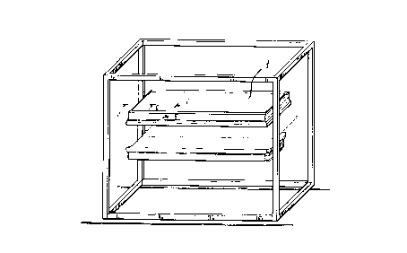
- Figure 1 the oven system including the
improved construction according to the present
invention;

6 ~177522
- Figures 2 and 3 the detail A of Figure 1, in
cross section respectively taken along the section
lines II-II and III-III;
- Figures 4 and 5 exploded cross-sectional
views of Figures 2 and 3 respectively;
- Figure 6 a detail of the system for
assembling a single electric resistance on the
supporting tile element thereof, and
- Figure 7 the detail of the assembly of
Figure 4, supported on the panel.
DESCRIPTION OF THE PREFERRED EMBODIMENT
The panel according to the present
invention has been generally indicated by the
reference number 1 in figure 1, in its assembled
condition at a heating station of a plastic
material thermoforming apparatus. The panel, which
constitutes one of the ovens of the mentioned
station, has an improved construction, essentially
comprising two portions:
- a front portion 2, i.e. facing the plastic
material to be heated, constituted by a metal box-
like element for supporting the electric
resistances 6; and
- a rear portion 3, i.e. facing the side
opposite to the side 2, holding the electric cables

7 ~ 1 7 75 2 2
4 connected to the clamps 5 of the electric
resistances 6, as well as the electric cables (not
shown) connecting the clamps 5 to the main electric
control panel.
As is clearly shown in figures 2 to 5,
the surface of the front portion 2 of the panel 1
which supports the heating elements or resistances
6 is constituted by a fretted sheet metal element,
on the rised portions (12) thereof are affixed said
electric resistances 6. Thus, the heating elements
constituted by said electric resistances will be
held well separated away from the bottom of that
construction portion 2 which is arranged near the
position of the cables 4.
Between the front portion 2 and rear
portion 3 of the panel 1 is arranged a thermally
insulating material 9, which is housed in the gap
11 separating the two mentioned construction
portions (figures 2 and 3). The mutual connection
of the front and rear portions of the oven, with
the thermally insulating layer 9 arranged
therebetween, is performed by using screws 7, upon
having applied a spacer sleeve element 10 (which is
advantageously coaxially arranged on the stem of
the respective screw 7, to provide the mentioned

8 217752~
gap 11. Inserts 8 made of a thermoinsulating
material are moreover provided on the contact
sections of the screws 7 and construction portions
2 and 3, in order to reduce any thermal bridging.
The connection of the electric
resistances 6 to the front portion 2 of the oven is
clearly shown in figure 4. The raised portion 12 of
the fretted construction 2 is provided with an
opening 13 in which is engaged the rear portion or
"base" 14 of the electric resistances 6. Before the
mentioned engagement, said base 14 will be provided
with a supporting tile element 15 constituting the
supporting element for supporting said electric
resistance on the mentioned fretted portion 12.
The, the base portion 4 of the electric
resistances 6 projecting under the supporting
element 15 will be locked in its position by means
of a small spring 16. The end connection of the
electric resistance 6, supporting element 15,
spring 16 system to the fretted portion 12 will be
then performed by screws 17 engaging on the
supporting element 15 and on guide elements 18
arranged on the bottom side of the fretted portions
or elements 12.
While the invention has been disclosed

9 2~77522
and illustrated with reference to a preferred
embodiment thereof, it should be apparent that the
disclosed embodiment is susceptible to several
modifications and variations all of which will come
within the scope of the invention. Thus, for
example, the configuration of the front and rear
portions of the oven can be different from the
disclosed configuration. The connecting means for
connecting the electric resistances to the front
portion 2 of the oven can be of any desired
suitable types, provided that they are equivalent
to the disclosed connecting element.

Representative Drawing
A single figure which represents the drawing illustrating the invention.
Administrative Status

2024-08-01:As part of the Next Generation Patents (NGP) transition, the Canadian Patents Database (CPD) now contains a more detailed Event History, which replicates the Event Log of our new back-office solution.

Please note that "Inactive:" events refers to events no longer in use in our new back-office solution.

For a clearer understanding of the status of the application/patent presented on this page, the site Disclaimer , as well as the definitions for Patent , Event History , Maintenance Fee  and Payment History  should be consulted.

Event History

Description Date
Inactive: IPC from MCD 2006-03-12
Application Not Reinstated by Deadline 2003-05-28
Time Limit for Reversal Expired 2003-05-28
Deemed Abandoned - Failure to Respond to Maintenance Fee Notice 2002-05-28
Inactive: Application prosecuted on TS as of Log entry date 2001-03-15
Inactive: Status info is complete as of Log entry date 2001-03-15
Letter Sent 2001-03-15
All Requirements for Examination Determined Compliant 2001-02-06
Request for Examination Requirements Determined Compliant 2001-02-06
Inactive: Cover page published 2000-12-21
Letter Sent 2000-02-17
Inactive: Multiple transfers 2000-01-05
Inactive: Multiple transfers 1999-11-01
Application Published (Open to Public Inspection) 1997-09-28

Abandonment History

Abandonment Date Reason Reinstatement Date
2002-05-28

Maintenance Fee

The last payment was received on 2001-05-15

Note : If the full payment has not been received on or before the date indicated, a further fee may be required which may be one of the following

  • the reinstatement fee;
  • the late payment fee; or
  • additional fee to reverse deemed expiry.

Patent fees are adjusted on the 1st of January every year. The amounts above are the current amounts if received by December 31 of the current year.
Please refer to the CIPO Patent Fees web page to see all current fee amounts.

Fee History

Fee Type Anniversary Year Due Date Paid Date
MF (application, 2nd anniv.) - small 02 1998-05-28 1998-05-26
Registration of a document 1998-06-30
MF (application, 3rd anniv.) - small 03 1999-05-28 1999-05-13
Registration of a document 1999-11-01
MF (application, 4th anniv.) - small 04 2000-05-29 2000-05-16
Request for examination - small 2001-02-06
MF (application, 5th anniv.) - small 05 2001-05-28 2001-05-15
Owners on Record

Note: Records showing the ownership history in alphabetical order.

Current Owners on Record
GAM IMPIANTI S.A.
Past Owners on Record
GIORGIO DE NICHILO
Past Owners that do not appear in the "Owners on Record" listing will appear in other documentation within the application.
Documents

To view selected files, please enter reCAPTCHA code :


To view images, click a link in the Document Description column. To download the documents, select one or more checkboxes in the first column and then click the "Download Selected in PDF format (Zip Archive)" or the "Download Selected as Single PDF" button.

List of published and non-published patent-specific documents on the CPD .

If you have any difficulty accessing content, you can call the Client Service Centre at 1-866-997-1936 or send them an e-mail at CIPO Client Service Centre.


Document
Description 
Date
(yyyy-mm-dd) 
Number of pages   Size of Image (KB) 
Representative drawing 1997-10-28 1 9
Representative drawing 2000-12-10 1 9
Drawings 1996-09-05 7 119
Description 1996-09-04 9 243
Abstract 1996-09-04 1 16
Claims 1996-09-04 3 79
Reminder of maintenance fee due 1998-01-28 1 111
Courtesy - Certificate of registration (related document(s)) 1998-07-27 1 140
Courtesy - Certificate of registration (related document(s)) 2000-02-16 1 115
Acknowledgement of Request for Examination 2001-03-14 1 179
Courtesy - Abandonment Letter (Maintenance Fee) 2002-06-24 1 183