Language selection

Search

Patent 2177885 Summary

Third-party information liability

Some of the information on this Web page has been provided by external sources. The Government of Canada is not responsible for the accuracy, reliability or currency of the information supplied by external sources. Users wishing to rely upon this information should consult directly with the source of the information. Content provided by external sources is not subject to official languages, privacy and accessibility requirements.

Claims and Abstract availability

Any discrepancies in the text and image of the Claims and Abstract are due to differing posting times. Text of the Claims and Abstract are posted:

  • At the time the application is open to public inspection;
  • At the time of issue of the patent (grant).
(12) Patent: (11) CA 2177885
(54) English Title: AIR ESCAPING MEANS
(54) French Title: MOYEN DE DESAERATION
Status: Expired
Bibliographic Data
(51) International Patent Classification (IPC):
  • B01D 46/10 (2006.01)
  • B01D 50/00 (2006.01)
(72) Inventors :
  • KARLSEN, MORTEN (Norway)
  • SANDVIK, ROBERT (Norway)
(73) Owners :
  • NORSK HYDRO A.S. (Norway)
(71) Applicants :
  • NORSK HYDRO A.S. (Norway)
(74) Agent: SMART & BIGGAR IP AGENCY CO.
(74) Associate agent:
(45) Issued: 2006-07-18
(22) Filed Date: 1996-05-31
(41) Open to Public Inspection: 1996-12-03
Examination requested: 2003-01-23
Availability of licence: N/A
(25) Language of filing: English

Patent Cooperation Treaty (PCT): No

(30) Application Priority Data:
Application No. Country/Territory Date
952218 Norway 1995-06-02

Abstracts

English Abstract

A de-aeration device for the separation of solid particles from a gas, comprising a container with an inlet for the supply of the gas contaminated with particles and an outlet for the purified gas. The cross-section of the container (4) is dimensioned in such a way that the gas velocity does not exceed the carrying velocity of the particles, that the gas flow is deflected at the inlet so that it flows mainly sideways in relation to the direction of through-flow of the container and that the outlet of the container (4) is provided with a filter cloth (9).


French Abstract

Un dispositif de désaération pour la séparation des particules solides provenant d'un gaz, comprenant un conteneur avec une entrée pour le gaz contaminé avec des particules et une sortie pour le gaz purifié. Les dimensions de la section transversale du conteneur (4) ont été conçues de telle sorte que la vitesse du gaz ne dépasse pas la vitesse de transport des particules, que le débit de gaz soit dévié à l'entrée afin qu'il s'écoule principalement sur le côté par rapport à la direction de circulation à l'intérieur du conteneur et que la sortie du conteneur (4) soit équipée d'un tissu filtrant (9).

Claims

Note: Claims are shown in the official language in which they were submitted.


5

CLAIMS:

1. A de-aeration device for separating solid
particles from a gas, said device comprising:

a container having an inlet for the supply of gas
contaminated with solid particles to be removed and a gas
outlet for discharging purified gas;

said container having a flow-through direction
extending from said inlet to said gas outlet;
said container having a cross section dimensioned
in a manner such that gas flows through said container at a
velocity that is less than a velocity necessary for the gas
to carry the solid particles;

means at said inlet to deflect the incoming gas to
be caused to flow substantially laterally of said flow-
through direction and

a filter cloth provided across said gas outlet.

2. A device as claimed in claim 1, wherein said gas
outlet is located above said inlet, and said inlet is
positioned at a lower part of said container.

3. A device as claimed in claim 2, further comprising
a separated particle outlet provided in said lower part of
said container.

4. A device as claimed in claim 3, wherein said lower
part of said container is inclined downwardly from said
inlet to said separated particle outlet.

5. A device as claimed in claim 1, wherein said
container further includes a separated particle outlet at a
position below said gas outlet.


6

6. A device as claimed in claim 1, wherein said
filter cloth is flexible.

7. A device as claimed in claim 6, wherein said
filter cloth is formed of glass fiber material.

8. A device as claimed in claim 1, wherein said
filter cloth is formed of glass fiber material.

9. A device as claimed in claim 1, wherein said inlet
comprises a connection pipe extending into said container in
a direction parallel to said flow-through direction, and
said means comprises a lateral opening from said pipe.

10. A device as claimed in claim 9, further comprising
a plate closing an inner end of said connection pipe.

11. A device as claimed in claim 9, wherein said means
further comprises a conical plate positioned in said
container at a position confronting an inner end of said
connection pipe.


Description

Note: Descriptions are shown in the official language in which they were submitted.


CA 02177885 2005-07-12
26625-231
1
AIR ESCAPING MEANS
BACKGROUND OF THE INVENTION
The present invention relates to a de-aeration
device for the separation of solid particles from air or
another gas.
Previous devices are known for the separation of
solid particles from a gas, which devices are based on the
creation of a centrifugal effect by means of an eddy current
so that the particles in the gas are hurled outwards against
a wall or similar in a chamber and then fall downwardly
therefrom.
The gas velocity employed for these known
solutions, which are shown, for example, in EP-A1-0424079,
must be relatively high for the centrifugal principle in
question to work. Furthermore, a majority of the smaller
particle fractions with a size of 1-20~m will have too low a
weight to be separated. The types of separator in question
are, therefore, not very effective with gases which contain
small particles and which flow at low velocities.
When conveying powdered material in fluidization
channels, small quantities of air are used to fluidize the
material. This air carries with it small particles which
will contaminate the surroundings when discharged into the
open air.
SUMMARY OF THE INVENTION
According to the invention there is provided a de-
aeration device for separating solid particles from a gas,
said device comprising: a container having an inlet for the
supply of gas contaminated with solid particles to be
removed and a gas outlet for discharging purified gas; said

CA 02177885 2005-07-12
26625-231
2
container having a flow-through direction extending from
said inlet to said gas outlet; said container having a cross
section dimensioned in a manner such that gas flows through
said container at a velocity that is less than a velocity
necessary for the gas to carry the solid particles; means at
said inlet to deflect the incoming gas to be caused to flow
substantially laterally of said flow-through direction and a
filter cloth provided across said gas outlet.
With the present invention it is possible to
manufacture a de-aeration device for the separation of solid
particles from a gas which is very simple and cheap to
produce and which is specially designed to separate small
particles from a gas which is flowing at low velocity, for
example air from fluidization channels as stated above.
BRIEF DESCRIPTION OF THE DRAWINGS
The invention will be described in further detail
in the following using examples and with reference to the
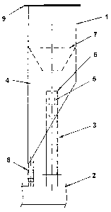
enclosed drawing which shows a schematic diagram of a
de-aeration device connected to a fluidization channel via a
connection pipe.
DETAILED DESCRIPTION OF THE INVENTION
A de-aeration device 1 comprises a drum or
container 4 which can preferably have a circular or
basically circular cross-section. The diameter (the cross-
sectional area) of the container must, in principle, be
sufficiently large such that the flow of air or gas does not
carry particles with it. For dust from aluminum oxide it has
been calculated that the air velocity in a connection pipe 3
from a fluidization channel 2 must be less than 2 m/s and
the air velocity in the container 4 must be less than
0.3 m/s.


2177885
An important point in this connection is that the supply pipe
must not have an opening which is directed longitudinally along
the container because this will produce a flow of air from the
opening of the pipe 3 which will be longitudinal along the
container 1 and which may be greater than the velocity of the
upper "carrying air flow". In the example shown in the drawing,
therefore, the connection pipe 3 extends into the container and
the air flows sideways out through the hole 5 in the side of the
pipe while the end of the pipe is provided with a sealing plate
6.
Thus it is important that the flow of air is deflected at the
inlet of the container. Another arrangement in this connection
would be to install another deflection device as shown in the
drawing, where a conical plate or similar 7 is shown. This will
contribute to directing parts of the flow of air downwards. The
plate 7 can preferably be perforated so that parts of the air
pass through the perforations in the plate at reduced velocity.
The container is also provided with a diagonal (funnel-shaped)
lower part which is designed to pass the separated, solid
particles to a separate return pipe 8.
In order to separate the very smallest particle fractions and any
larger particle fractions which have not been separated in the
lower part of the container, a flexible filter cloth 9 is
arranged on the top of the container; this filter cloth is
preferably of glass fibre material.
The flexibility of the cloth has proved to have the result that
the cloth is self-cleaning. The reason is that the cloth will
bulge out or in on account of changes in pressure in the


2177885
container 4 and thus cause the adhered particles to "peel off".
It should be noted that the invention as it is defined in the
claims is not restricted to the solution which is shown in the
drawing and described above. Thus, instead of two pipes, one
connection pipe 3 for the supply of the gas contaminated with
particles and one return pipe 8 for separated particles, just one
pipe can be used, but with two separate channels for the two
purposes. Thus the pipe 3 with the greater diameter can be
arranged where the pipe 8 is shown in the drawing so that one
channel in pipe 3 can be used for the supply of the gas
contaminated with particles and the other channel can be used to
return the separated particles. It is, however, important that
the other channel for the return of the particles or pipe 8 has a
much smaller diameter than the pipe 3 for supplying the gas
contaminated with particles.

Representative Drawing
A single figure which represents the drawing illustrating the invention.
Administrative Status

For a clearer understanding of the status of the application/patent presented on this page, the site Disclaimer , as well as the definitions for Patent , Administrative Status , Maintenance Fee  and Payment History  should be consulted.

Administrative Status

Title Date
Forecasted Issue Date 2006-07-18
(22) Filed 1996-05-31
(41) Open to Public Inspection 1996-12-03
Examination Requested 2003-01-23
(45) Issued 2006-07-18
Expired 2016-05-31

Abandonment History

There is no abandonment history.

Payment History

Fee Type Anniversary Year Due Date Amount Paid Paid Date
Application Fee $0.00 1996-05-31
Registration of a document - section 124 $0.00 1996-08-22
Maintenance Fee - Application - New Act 2 1998-06-01 $100.00 1998-04-28
Maintenance Fee - Application - New Act 3 1999-05-31 $100.00 1999-04-15
Maintenance Fee - Application - New Act 4 2000-05-31 $100.00 2000-04-18
Maintenance Fee - Application - New Act 5 2001-05-31 $150.00 2001-04-05
Maintenance Fee - Application - New Act 6 2002-05-31 $150.00 2002-04-10
Request for Examination $400.00 2003-01-23
Maintenance Fee - Application - New Act 7 2003-06-02 $150.00 2003-04-07
Maintenance Fee - Application - New Act 8 2004-05-31 $200.00 2004-05-04
Maintenance Fee - Application - New Act 9 2005-05-31 $200.00 2005-04-07
Maintenance Fee - Application - New Act 10 2006-05-31 $250.00 2006-04-06
Final Fee $300.00 2006-05-08
Maintenance Fee - Patent - New Act 11 2007-05-31 $250.00 2007-04-10
Maintenance Fee - Patent - New Act 12 2008-06-02 $250.00 2008-04-10
Maintenance Fee - Patent - New Act 13 2009-06-01 $250.00 2009-04-20
Maintenance Fee - Patent - New Act 14 2010-05-31 $250.00 2010-05-20
Maintenance Fee - Patent - New Act 15 2011-05-31 $450.00 2011-05-19
Maintenance Fee - Patent - New Act 16 2012-05-31 $450.00 2012-05-16
Maintenance Fee - Patent - New Act 17 2013-05-31 $450.00 2013-05-21
Maintenance Fee - Patent - New Act 18 2014-06-02 $450.00 2014-05-19
Maintenance Fee - Patent - New Act 19 2015-06-01 $450.00 2015-05-19
Owners on Record

Note: Records showing the ownership history in alphabetical order.

Current Owners on Record
NORSK HYDRO A.S.
Past Owners on Record
KARLSEN, MORTEN
SANDVIK, ROBERT
Past Owners that do not appear in the "Owners on Record" listing will appear in other documentation within the application.
Documents

To view selected files, please enter reCAPTCHA code :


To view images, click a link in the Document Description column. To download the documents, select one or more checkboxes in the first column and then click the "Download Selected in PDF format (Zip Archive)" or the "Download Selected as Single PDF" button.

List of published and non-published patent-specific documents on the CPD .

If you have any difficulty accessing content, you can call the Client Service Centre at 1-866-997-1936 or send them an e-mail at CIPO Client Service Centre.


Document
Description 
Date
(yyyy-mm-dd) 
Number of pages   Size of Image (KB) 
Representative Drawing 1998-03-06 1 6
Cover Page 1996-05-31 1 16
Abstract 1996-05-31 1 15
Description 1996-05-31 4 128
Claims 1996-05-31 1 22
Drawings 1996-05-31 1 8
Description 2005-07-12 4 141
Claims 2005-07-12 2 54
Representative Drawing 2005-11-02 1 4
Cover Page 2006-06-21 1 30
Assignment 1996-05-31 7 310
Prosecution-Amendment 2003-01-23 1 64
Prosecution-Amendment 2003-02-21 1 35
Correspondence 2006-05-08 1 39
Prosecution-Amendment 2005-01-12 3 76
Prosecution-Amendment 2005-07-12 8 285