Language selection

Search

Patent 2178023 Summary

Third-party information liability

Some of the information on this Web page has been provided by external sources. The Government of Canada is not responsible for the accuracy, reliability or currency of the information supplied by external sources. Users wishing to rely upon this information should consult directly with the source of the information. Content provided by external sources is not subject to official languages, privacy and accessibility requirements.

Claims and Abstract availability

Any discrepancies in the text and image of the Claims and Abstract are due to differing posting times. Text of the Claims and Abstract are posted:

  • At the time the application is open to public inspection;
  • At the time of issue of the patent (grant).
(12) Patent: (11) CA 2178023
(54) English Title: FLEXIBLE STEP ASSEMBLY FOR VEHICLES
(54) French Title: SYSTEME DE MARCHES SOUPLES POUR VEHICULES
Status: Term Expired - Post Grant Beyond Limit
Bibliographic Data
(51) International Patent Classification (IPC):
  • B60R 03/02 (2006.01)
  • B62D 25/22 (2006.01)
  • E04G 03/00 (2006.01)
(72) Inventors :
  • RINALDI, RANDY D. (Canada)
(73) Owners :
  • RANDY D. RINALDI
(71) Applicants :
  • RANDY D. RINALDI (Canada)
(74) Agent: ROSEANN B. CALDWELLCALDWELL, ROSEANN B.
(74) Associate agent:
(45) Issued: 2006-03-21
(22) Filed Date: 1996-06-03
(41) Open to Public Inspection: 1997-12-04
Examination requested: 2003-05-15
Availability of licence: N/A
Dedicated to the Public: N/A
(25) Language of filing: English

Patent Cooperation Treaty (PCT): No

(30) Application Priority Data: None

Abstracts

English Abstract

This invention relates to a flexible step assembly for vehicles, which includes a number of vertically disposed horizontal steel tread members attached at their ends to flexible side members. A spring loaded assembly is attached to the upper ends of each side member, the spring loaded assembly is of two part construction, top part being fixed to a location on the vehicle for use, the lower part being separable under impact from the top part, but upon release of loading, recoupled by a spring and its associated components.


French Abstract

La présente invention concerne un ensemble de marchepied souple pour véhicules comprenant un certain nombre d'éléments de giron en acier disposés horizontalement et rattachés en leurs extrémités à des éléments latéraux souples. Un ensemble monté sur ressort est rattaché aux extrémités supérieures de chaque élément latéral, l'ensemble monté sur ressort étant de construction en deux parties, une partie supérieure étant fixée sur un emplacement du véhicule pour être utilisée, la partie inférieure étant séparable de la partie supérieure sous l'effet d'un impact, mais, la charge cessant, celle-ci est couplée à nouveau au moyen d'un ressort et de ses composants associés.

Claims

Note: Claims are shown in the official language in which they were submitted.

What is claimed is:
1. ~A flexible step assembly for vehicles comprising in combination: a first
flexible,
vertically depending side member and a second flexible, vertically depending
side
member, each of the first and the second side members having an upper portion;
at
least one horizontally extending tread member attached between the first and
the
second side members; a first shock absorbing means operably connected to the
upper
portion of the first side member and a second shock absorbing means operably
connected to the upper portion of the second side member, each of the first
and second
shock absorbing means including an upper section and a lower section, the
upper
section and the lower section being interconnected and partially separable
under
impact, sufficient to permit the step assembly to move in a direction of
impact such that
damage of the step assembly due to impact is substantially prevented, each of
the first
and the second shock absorbing means including a spring adapted for
interconnection
between the upper section and the lower section, the spring serving to
recouple the
upper section and the lower section when separated by impact and the upper
section of
each of the first and the second shock absorbing means comprise an elongate
hollow
tubular member having a lower opening and a flange extending about the lower
opening, the flange having a recess on its bottom surface and wherein the
lower section
of each of the first and the second shock absorbing means comprises a plate,
the plate
being configured to interlock with the recess on the flange.
2. ~The flexible step assembly according to claim 1 wherein the spring means
includes a compression spring.
3. ~The flexible step assembly according to claim 1 wherein the first and the
second
side members are of rubber.
4. ~The flexible step assembly according to claim 1 wherein the plate and the
recess
are formed to correspond so that the plate can interlock with the recess in
one
orientation only.

5. ~The flexible step assembly according to claim 1 the elongate tubular
member of
the upper section being closed at a top end and housing the spring, the spring
being a
compression spring, a cap disposed within the elongate tubular member above
the
compression spring and free to ride vertically within the elongate tubular
member, a
chain attached to the cap and extending centrally through the spring, through
the lower
opening of the elongate member and being connected to the lower section.
6. ~The flexible step assembly according to claim 1 wherein the upper section
of
each of the first and the second shock absorbing means is adapted to be
fixedly held on
a portion of a vehicle.
7. ~A flexible step assembly for vehicles comprising in combination: a pair of
flexible,
vertically depending side members, each of the pair of side members having an
upper
portion; at least one horizontally extending tread member attached between the
side
members; a shock absorbing means operably connected to the upper portion of
each
side member, each of the shock absorbing means including an upper section and
a
lower section, the upper section and the lower section being interconnected
and
partially separable under impact, sufficient to permit the step assembly to
move in a
direction of impact such that damage by impact to the step assembly is
substantially
prevented, the upper section of each shock absorbing means including an
elongate
tubular member having a lower opening and being closed at a top end, the
elongate
tubular member housing a compression spring adapted to act between the upper
section and the lower section serving to recouple the upper section and the
lower
section when separated by impact; a cap disposed within the elongate tubular
member
above the compression spring and being free to ride vertically within the
elongate
tubular member, a chain attached to the cap and extending centrally through
the spring,
through the lower opening of the elongate tubular member and being connected
to the
lower section.
8. ~The flexible step assembly according to claim 7 wherein the side members
are of
rubber.

9. ~The flexible step assembly according to claim 7 wherein a flange extends
about
the lower opening, the flange having a recess on its bottom surface and the
lower
section of each shock absorbing means comprises a plate, the plate being
configured to
interlock with the recess on the flange.
10. ~The flexible step assembly according to claim 9 wherein the plate and the
recess
are formed to correspond so that the plate can interlock with the recess in
one
orientation only.
11. ~The flexible step assembly according to claim 7 wherein the upper section
of the
shock absorbing means is adapted to be fixedly held on a portion of a vehicle.
12. ~The flexible step assembly according to claim 7 wherein the lower section
of the
shock absorbing means includes an intermediate member formed with a hole
therethrough and the chain means has attached thereto at an end opposite the
cap a
threaded rod, the threaded rod extending through the hole of the intermediate
member
and nut means threadedly engaged on the threaded rod below the intermediate
member.
13. ~A flexible step assembly for vehicles comprising in combination: a pair
of flexible,
vertically depending side members, each of the pair of side members having a
upper
portion; at least one horizontally extending tread member attached between the
side
members; a shock absorbing means operably connected to the upper portion of
each
side member, each of the shock absorbing means including an upper section and
a
lower section, the upper section and the lower section being interconnected
and
partially separable under impact, sufficient to permit the step assembly to
move in the
direction of impact such that damage due to impact to the step assembly is
substantially
prevented, the shock absorbing means including spring means adapted for
interconnection between the upper section and the lower section, the spring
means
serving to recouple the upper section and the lower section when separated by
impact;
the upper section of each shock absorbing means comprising an elongate tubular
member having a lower opening and a flange extending about the lower opening,
the
flange having a recess on its bottom surface and wherein the lower section of
each

shock absorbing means comprises a plate, the plate being configured to
interlock with
the recess on the flange.
14. The flexible step assembly according to claim 13 wherein the plate and the
recess are formed to correspond so that the plate can interlock with the
recess in one
orientation only.
15. The flexible step assembly according to claim 13 wherein the spring means
includes a compression spring.
16. A flexible step assembly according to claim 13 wherein the side members
are of
rubber.
17. The flexible step assembly according to claim 13 the elongate tubular
member of
the upper section being closed at a top end and housing the spring, the spring
being a
compression spring; a cap disposed within the elongate tubular member above
the
compression spring and free to ride vertically within the elongate tubular
member, a
chain attached to the cap and extending centrally through the spring through
the lower
opening of the elongate member and being connected to the lower section.
18. The flexible step assembly according to claim 13 wherein the upper section
of
the shock absorbing means is adapted to be fixedly held on a portion of a
vehicle.

Description

Note: Descriptions are shown in the official language in which they were submitted.


l
The invention relates in general to a flexible step
assembly for attachment to and for use on vehicles,
particularly of the commercial type, namely vehicles used
for industrial purposes such as road making equipment and
heavy farm equipment.
There has long been a requirement for steps to be
provided to allow operators or maintenance personnel ready
access to, for example, the body of large vehicles.
Such step assemblies have been provided as permanent
structures, fixedly attached to depend from the vehicle
chassis. However, due to the nature of the terrain over
which these vehicles operate, these prior assemblies are
easily damaged by impact with the ground or other
obstructions, and are constantly in need of repair and/or
replacement.
It is therefore a principle object of the present
invention to provide a step assembly that is on the one
hand flexible enough to withstand high impact without
substantial damage and on the other hand provide a rigid
enough structure to withstand normal use without flexing
under the weight of the user.
The invention therefore comprises a flexible step
assembly for vehicles including in combination, a plurality
of horizontally extending tread members equidistantly
spaced one above the other and anchored at each of their
- 2 -

ends to a flexible, vertically depending side member. A
shock absorber assembly is operably attached to the
uppermost section of each of the side members, each shock
absorber assembly comprising an upper and lower
interconnected section, each of said two interconnected
sections being independently and partially separable under
impact sufficient to permit the step assembly to move in
the direction of impact such that damage to the step
assembly is substantially prevented. Each shock absorber
assembly includes a spring arrangement adapted for
interconnection between each of the two interconnected or
intercoupled sections, the spring assembly serving to
recouple the two interconnected sections as Separated by
impact to return the step assembly to the in use position.
The invention will now be described, by way of example
only, reference being had to the accompanying drawings in
which:
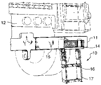
Figure 1 shows a step assembly according to the
invention operably mounted in relation to the front bumper
of a vehicle;
Figure 2 is a schematic representation of the step
assembly of Figure 1 under side impact;
Figure 3 is a side elevational view of the step
assembly under front impact;
Figure 4 is a front elevational view of the step
- 3 -

21 ~~ ~2.~
assembly according to the invention;
Figure 5 is a side elevational view of the step
assembly of Figure 4, in part section; and
Figure 6 is an exploded view of the component parts
which form the shock absorbing system, shown in part
section on Figure 5.
Looking specifically at the drawings, Figure 1 shows
the general arrangement of the step assembly 10 mounted to
the front bumper 11 of a large vehicle 12 (shown in phantom
outline). While various mounting methods are available, in
this embodiment, attachment is by bolts 14 to the bottom
flange 15 of the bumper 11.
The step construction itself comprises in this
specific embodiment, two tread sections 16 which are formed
of steel, and mounted to extend between two side members
17, formed from substantially thick rubber material. The
tread section 16 are attached to each side member 17 by
bolts 18 and reinforcing plates 19. As can be seen from
Figure 4, the plates 19 and bolts 18 sandwich a two-ply
rubber reinforced belting.
Each composite side member 17 is attached as by bolts
20 and reinforcing plate 21 to an associated shock absorber
system, generally indicated at 22, the separate components
can be seen in more detail in Figures 5 and 6.
System 22 comprises essentially in two separable
- 4 -

2~~~~C3
sections 23 and 24. Upper section 23 comprises a tubular
member 25, closed off at its upper end by a cap 26, and
attached as by welding at its opposite lower end by a
flange 27. Flange 27 being adapted to be attached, as by
bolts directly to the chassis of the vehicle, or by way of
a bumper attachment (not shown). The underside of flange
27 is provided with a circular perturbulence 28, which is
recessed at 29. The configuration of the recess being
substantially circular but with a straight-edged portion
30. A hole 31 is provided through flange 27 which when
welded to member 25 is in axial alignment with the center
of member 25.
Looking now to bottom section 24, this as can be seen
from Figure 6 comprises a length of open-ended square steel
tubing 32 welded to a backing plate 33, the latter being
the means by which the assembly is attached, by bolts 34,
to a side member 17. Inside tubing 32 and located a short
distance from the bottom of the tube is a member 35 which
is attached internal to the walls of tube 32 as by welding.
Member 35 is provided with a centrally aligned hole 35A
extending axially therethrough.
The final component of section 24 is a top-plate 36
which is attached as by welding to the top of tube 32 to
close off same. Plate 36 is configured dimensionally to
fit and to seat within recess 29 on the underside of flange
- 5 -

217~~y
27 of upper section 23. A centrally aligned hole 36A is
provided in plate 36.
Top and bottom sections 23 and 24 are coupled together
to form a shock or impact loading assembly, by the
provision of a spring 37; chain 38 with associated top cap
39; threaded rod 40, and bottom nut 41. As can be seen
from Figure 5, the spring 37 is contained within tubular
member 25 of top section 23, and chain 38 passes centrally
through spring 37 and is connected top cap or plate 39.
Chain 38 extends from top section 23 into bottom
section 24, through hole 31 in flange 27; through hole 36A
and plate 36 to be attached to the top of threaded rod 40.
Rod 40 then passes through hole 35A to be finally secured
by nut 41.
By tightening nut 41, spring 37 is drawn into
compression, plate 36 is snugly located within a recess 29
thus bringing the entire assembly into tension, ie: the
spring under compression, to maintain the steps in a
vertical and downwardly extending position.
By adjusting the spring compression the steps remain
essentially rigid when being ascended by an operator, for
example, the utilization of springs which require
approximately 1300 pounds pressure to compress, is
sufficient to hold a 225 pound person, and not deviate from
the vertical position when being used.
- 6 -

2178a~~
It will also be appreciated from the above description
that when the step assembly is under impact loads from any
direction, the springs 37 will allow the lower section 24
of the shock absorbing assembly to partially separate from
the upper section 23 in the area of plate 36 and its inter-
relationship with recess 29 in flange 27. Plate 36 will be
forced out of recess 29 on impact, which will permit
approximately 90 degrees of movement, in the direction of
impact, of the step assembly. After impact, however, the
spring 37 will return the assembly back to its original
vertical position, wherein plate 36 will, by virtue of its
configuration mate back into the same position with recess
29. In other words, the orientation of the assembly
following spring return will be as before impact.
It is to be understood that the embodiment of the
invention herein described is merely illustrative of the
application of the principles of the invention. Reference
herein to details of the illustrated embodiment is not
intended to limit the scope of the claims which themselves
recite those features regarded as essential to the
invention.
The scope of the invention is therefore to be
considered broadly defined and is specified in the appended
claims.
_ 7 _

Representative Drawing
A single figure which represents the drawing illustrating the invention.
Administrative Status

2024-08-01:As part of the Next Generation Patents (NGP) transition, the Canadian Patents Database (CPD) now contains a more detailed Event History, which replicates the Event Log of our new back-office solution.

Please note that "Inactive:" events refers to events no longer in use in our new back-office solution.

For a clearer understanding of the status of the application/patent presented on this page, the site Disclaimer , as well as the definitions for Patent , Event History , Maintenance Fee  and Payment History  should be consulted.

Event History

Description Date
Inactive: Expired (new Act pat) 2016-06-03
Inactive: Adhoc Request Documented 2009-04-06
Inactive: Payment - Insufficient fee 2009-04-06
Small Entity Declaration Determined Compliant 2009-03-16
Inactive: Late MF processed 2009-03-16
Small Entity Declaration Request Received 2009-03-16
Letter Sent 2008-06-03
Grant by Issuance 2006-03-21
Inactive: Cover page published 2006-03-20
Inactive: IPC from MCD 2006-03-12
Inactive: Final fee received 2006-01-03
Pre-grant 2006-01-03
Letter Sent 2005-12-08
Notice of Allowance is Issued 2005-12-08
Inactive: IPC assigned 2005-12-06
Inactive: Approved for allowance (AFA) 2005-11-25
Amendment Received - Voluntary Amendment 2005-11-03
Inactive: S.30(2) Rules - Examiner requisition 2005-05-03
Inactive: Application prosecuted on TS as of Log entry date 2003-12-03
Inactive: Status info is complete as of Log entry date 2003-12-03
Letter Sent 2003-06-19
All Requirements for Examination Determined Compliant 2003-05-15
Request for Examination Requirements Determined Compliant 2003-05-15
Request for Examination Received 2003-05-15
Application Published (Open to Public Inspection) 1997-12-04
Small Entity Declaration Determined Compliant 1996-06-03

Abandonment History

There is no abandonment history.

Maintenance Fee

The last payment was received on 2005-01-20

Note : If the full payment has not been received on or before the date indicated, a further fee may be required which may be one of the following

  • the reinstatement fee;
  • the late payment fee; or
  • additional fee to reverse deemed expiry.

Patent fees are adjusted on the 1st of January every year. The amounts above are the current amounts if received by December 31 of the current year.
Please refer to the CIPO Patent Fees web page to see all current fee amounts.

Fee History

Fee Type Anniversary Year Due Date Paid Date
MF (application, 2nd anniv.) - small 02 1998-06-03 1998-04-30
MF (application, 3rd anniv.) - small 03 1999-06-03 1999-02-10
MF (application, 4th anniv.) - small 04 2000-06-05 2000-01-21
MF (application, 5th anniv.) - small 05 2001-06-04 2000-12-20
MF (application, 6th anniv.) - small 06 2002-06-03 2001-12-19
MF (application, 7th anniv.) - small 07 2003-06-03 2003-05-15
Request for examination - small 2003-05-15
MF (application, 8th anniv.) - small 08 2004-06-03 2004-02-18
2005-01-20
MF (application, 9th anniv.) - small 09 2005-06-03 2005-01-20
Final fee - small 2006-01-03
MF (patent, 10th anniv.) - small 2006-06-05 2006-03-10
2006-03-10
MF (patent, 11th anniv.) - small 2007-06-04 2007-05-29
Reversal of deemed expiry 2008-06-03 2008-04-17
MF (patent, 12th anniv.) - standard 2008-06-03 2008-04-17
MF (patent, 13th anniv.) - small 2009-06-03 2009-03-16
MF (patent, 14th anniv.) - small 2010-06-03 2010-02-26
MF (patent, 15th anniv.) - small 2011-06-03 2011-02-25
MF (patent, 16th anniv.) - small 2012-06-04 2012-02-17
MF (patent, 17th anniv.) - small 2013-06-03 2013-02-20
MF (patent, 18th anniv.) - small 2014-06-03 2014-02-21
MF (patent, 19th anniv.) - small 2015-06-03 2015-05-14
2015-05-14
Owners on Record

Note: Records showing the ownership history in alphabetical order.

Current Owners on Record
RANDY D. RINALDI
Past Owners on Record
None
Past Owners that do not appear in the "Owners on Record" listing will appear in other documentation within the application.
Documents

To view selected files, please enter reCAPTCHA code :


To view images, click a link in the Document Description column. To download the documents, select one or more checkboxes in the first column and then click the "Download Selected in PDF format (Zip Archive)" or the "Download Selected as Single PDF" button.

List of published and non-published patent-specific documents on the CPD .

If you have any difficulty accessing content, you can call the Client Service Centre at 1-866-997-1936 or send them an e-mail at CIPO Client Service Centre.


Document
Description 
Date
(yyyy-mm-dd) 
Number of pages   Size of Image (KB) 
Representative drawing 1998-01-01 1 12
Abstract 1996-06-02 1 15
Description 1996-06-02 6 199
Drawings 1996-06-02 3 83
Claims 1996-06-02 3 85
Claims 2005-11-02 4 182
Drawings 2005-11-02 3 77
Representative drawing 2005-11-20 1 15
Reminder of maintenance fee due 1998-02-03 1 111
Reminder - Request for Examination 2003-02-03 1 112
Acknowledgement of Request for Examination 2003-06-18 1 173
Commissioner's Notice - Application Found Allowable 2005-12-07 1 161
Maintenance Fee Notice 2009-04-05 1 170
Late Payment Acknowledgement 2009-04-05 1 163
Fees 2003-05-14 1 24
Correspondence 1997-02-20 8 210
Fees 1999-02-09 1 33
Fees 1998-04-29 1 33
Fees 2001-12-18 1 28
Fees 2000-01-20 1 27
Fees 2000-12-19 1 28
Fees 2004-02-17 1 28
Fees 2005-01-19 1 29
Correspondence 2006-01-02 1 27
Fees 2006-03-09 1 29
Fees 2007-05-28 1 33
Fees 2008-04-16 1 32
Correspondence 2009-03-15 3 83
Fees 2009-03-15 3 83
Fees 2009-03-15 1 32