Note: Descriptions are shown in the official language in which they were submitted.
2178185
PATENT
450100-3535
TELEVISION SIGNAL RECORDING/REPRODUCING
APPARATUS AND METHOD WITH DC SHIFTER
BACKGROUND OF THE INVENTION
The present invention relates to digitally recording
and reproducing a television signal and, more particularly, to
digitally recording and reproducing a PAL plus television signal.
Television signals are broadcast using various
transmission standards. PAL is one such standard primarily
employed in European countries. PAL plus is the next generation
broadcasting standard of PAL that provides higher image quality
than its predecessor. Another distinctive feature of the PAL
plus standard is that the television picture has an aspect ratio
of 9 . 16, which is considered more aesthetically pleasing than
the aspect ratio of 3 . 4 which is the aspect ratio primarily
used heretofore by television receivers. As shown in Fig. 27A,
the PAL plus image of Fig. 27B is superimposed on the 3 . 4
aspect ratio of the conventional television receiver, image
demonstrating the differences in aesthetic appearance between the
two standards. The PAL plus standard is compatible with PAL
television receivers and thus, the PAL plus television signal is
derived from the PAL television signal. To obtain the 9 . 16
aspect ratio, a vertical conversion circuit decimates the PAL
plus television signal using a 3 to 4 decimation process.
However, the decimation process deteriorates the
vertical resolution of the PAL plus image. To correct this
SONY.15\3535.APP - 1
2178185
PATENT
450100-3535
vertical deterioration the PAL plus standard transmits a vertical
resolution signal (hereinafter referred to as a helper signal)
during the upper and lower invalid screen portions (Fig. 28) of
the PAL plus television signal. The helper signal is employed by
the PAL plus television receiver to reconstruct the lost vertical
resolution.
A problem arises, however, when the PAL plus signal is
recorded digitally as, for example, occurs in a discrete cosine
transform DCT process. In the DCT process, each television frame
is divided into blocks of pixels (8 x 8, for example), and each
block is DCT transformed. As shown in Fig. 31, the 8 x 8 DCT
blocks extend into the upper invalid screen portion where the
helper signal is stored. Consequently, portions of the helper
signal are processed with the main screen portion in the same DCT
block. Because the signal values between the DCT blocks and the
helper signal are significantly different, the DCT process
calculates erroneous DCT coefficients and a resultant image
distortion occurs. In this case, the invalid screen portions
include pixel information from the middle of the television
picture, and the resultant distortion affects the center of the
picture as shown in Fig. 32.
SONY.15\3535.APP - 2 -
. .~ ~ . 2178185
PATENT
450100-3535
OBJECTS AND SUMMARY OF THE INVENTION
An object of the invention, therefor, is to provide a
television signal recording/reproducing apparatus and method for
preventing DCT distortion.
A further object of the invention is to provide a
television signal recording/reproducing technique which DC shifts
the signals within a respective compression block containing both
a vertical resolution signal and a component video signal to a DC
set up value.
A further object of the invention is to provide a
television signal recording/reproducing technique for DC shifting
a vertical resolution signal to a DC set up value.
A further object of the invention is to provide a
television signal recording/reproducing technique which DC shifts
a component signal to the DC set up value.
Yet another object of the invention is to provide a
television signal recording/reproducing technique for digitally
recording and reproducing a PAL plus signal without a loss in
vertical resolution.
In accordance with the above objectives, the present
invention provides a television signal recording/reproducing
apparatus and method with DC shifter. The DC shifter shifts a
signal within a compression block to a DC set up value such that
compression distortion arising from the compression of signals of
SONY.15\3535.APP - 3 -
2178185
PATENT
450100-3535
varying DC offsets within the compression block during digital
recording is prevented.
Upon reproducing the digitally recorded television
signal, the present invention removes the DC set up value from
the compression block in order to retrieve the recorded
television signal.
Since the vertical resolution signal and the component
video signal are normalized to a DC set up value, DCT distortion
does not arise when the signals are compressed during recording.
Thus, the compression blocks at the border between the upper
invalid portion and the main screen portion of the television
signal do not cause a DCT compression problem and the vertical
resolution of the resulting image is completely restored.
BRIEF DESCRIPTION OF THE DRAWINGS
Fig. 1 is a schematic diagram showing the relation
between lines and DCT blocks;
Fig. 2 is a block diagram showing a recording apparatus
for a PAL plus signal according to the present invention;
Fig. 3 is a schematic diagram showing a digital
normalization process of the PAL plus signal;
Fig. 4 is a block diagram showing the PAL plus record
side processing circuit of Fig. 2;
Fig. 5 is a block diagram of a recording side of a
digital VCR;
SONY.15\3535.APP - 4
2178185
PATENT
450100-3535
Figs. 6A to 6E are schematic diagrams showing levels of
signals recorded on a recording tape;
Fig. 7 is a block diagram showing a reproduction side
of a digital VCR;
Fig. 8 is a block diagram showing the reproducing
apparatus for reproducing a PAL plus signal according to the
present invention;
Fig. 9 is a block diagram of the PAL plus reproduction
side processing circuit of Fig. 8;
Figs. l0A and lOB are schematic diagrams showing a
track format of the tape;
Fig. 11 is a schematic diagram showing the arrangement
of each track of the tape;
Fig. 12 is a schematic diagram showing the arrangement
of data in each track of the tape;
Fig. 13 is a schematic diagram showing an hierarchical
structure of application ID blocks;
Figs. 14A and 14B are schematic diagrams of a specific
example of data storage in each track of the tape;
Fig. 15 is a schematic diagram showing the structure of
a pack of data;
Fig. 16 is a schematic diagram showing a data structure
of a header arranged in the pack of Fig. 15;
Fig. 17 is a schematic diagram showing a TR pack;
SONY.15\3535.APP - 5
2178185
PATENT
450100-3535
Fig. 18 is a schematic diagram showing an audio format
for a track of the tape;
Figs. 19A and 19B are schematic diagrams of the pre-
sync and post-sync blocks of Fig. 18;
Fig. 20 is a schematic diagram showing the audio sync
blocks of the Fig. 18 arrangement on the tape;
Fig. 21 is a schematic diagram of the arrangement of
audio packs in Fig. 20 on a tape;
Fig. 22 is a schematic diagram of a video area recorded
on the tape;
Fig. 23 is a schematic diagram of a video sync block
which may contain auxiliary video data;
Fig. 24 is a schematic diagram showing video sync
blocks of Fig. 23 stacked into buffers;
Fig. 25 is a schematic diagram of a sub-code area
recorded on the tape;
Fig. 26 is a schematic diagram of a sub-code sync
block;
Figs. 27A and 27B are schematic diagrams of a
conventional receiver and a PAL plus receiver;
Fig. 28 is a schematic diagram showing a line
assignment and a pixel assignment of a PAL plus signal;
Figs. 29A and 29B are graphs of the component signals
comprising the PAL plus signal in the frequency domain;
SONY.15\3535.APP - 6
2178185
PATENT
450100-3535
Figs. 30A and 30B are schematic diagrams of a sampling
standard for digital VCR recording according to 625 lines/50 Hz
system;
Fig. 31 is a schematic diagram showing a row of DCT
blocks which include both the helper portion and the picture
portion; and
Fig. 32 shows the distortion effect caused by
compressing the DCT blocks of Fig. 31.
DETAILED DESCRIPTION OF THE PREFERRED EMBODIMENTS
Referring now to the drawings, wherein like reference
numerals designate identical or corresponding parts throughout,
the present invention will be described.
PAL Plus Standard
The PAL plus standard now will be explained in more
detail with particular attention to the above-described
distortion problem.
The format for transmitting a PAL plus signal
corresponding to a frame of a television image is shown in Fig.
28. The PAL plus transmission is composed of 625 lines of a PAL
plus signal sampled at 13.5 MHz. The samples begin on line 23 at
sample number 10. The sampled PAL plus signal is transmitted. in
a 4:2:2 (Y . CB . CR) format, meaning that the blue color
difference signal (CB) and the red color difference signal (CR)
SONY.15\3535.APP - 7 -
_ 2178185
PATENT
450100-3535
are sampled twice for every four samplings of the luminance (Y)
signal. The 4:2:2 format is generated by separating the PAL plus
signal into two fields, field 1 and field 2 (depicted in Fig. 28
as the two separate areas designated "Letter Box"), and
alternatively transmitting the color difference signals in each
field. Since the blue color difference signal (CH) is B-Y and
the red color difference signal (CR) is R-Y, the luminance signal
(Y) can be extracted from each color difference signal in the
fields. Since both fields are composed of luminance signals (Y)
on each line, while each field is composed of alternating color
difference signals (CB, CR) the 4:2:2 (Y . CH . CR) format is
satisfied.
Figs. 30A and 30B depict how the PAL plus standard
reintegrates the samples from each of the fields, field 1 and
field 2, from the 4:2:2 transmission format. Fig. 30A shows that
the luminance signals (Y) are extracted from each line in each
field and reassembled by alternatively selecting the lines from
each field since each line in the main portions of both fields 1
and 2 contains a luminance signal (Y). Thus, the luminance
signal (Y) is retrieved from lines 335, 23, 336, 24, 337, 25 and
so on, in sequential order. On the other hand, the color
difference signals CB and CR are located on alternate lines in
each of fields 1 and 2. For example, line 23 in field 1 includes
color difference signals (CR) and subsequent line 24 in field 1
SONY.15\3535.APP
2178185
PATENT
450100-3535
includes color difference signals (CB}. Thus, alternating the
fields from which the lines are selected results in the pattern
shown by Fig. 30B wherein every two lines contain the same type
of color difference signal. It will be seen that the sampling
rate of the color difference signals is one-half the sampling
rate of the luminance signal.
The contents of each field will now be described in
more detail with reference to Fig. 28. The useful portion of
field 1 begins on line 23 at sample number 10 with a wide screen
signal (WSS} which indicates the presence of the helper signal.
The WSS signal is followed on line 23 by a helper reference burst
signal which is used to decode the helper signal at the receiving
television apparatus. The helper signal for field 1 is
transmitted during the upper and lower invalid screen portions of
field 1 on lines 24 to 59 and 275 to 310, respectively. Next,
the picture data of the PAL plus signal, which has been decimated
and DCT processed, is transmitted during the main screen portion
on lines 60 to 274 of field 1. Similarly, field 2 transmits the
helper signal during the upper and lower invalid screen portions
on lines 336 to 371 and 587 to 622, respectively. The decimated
and DCT processed image is transmitted during the main screen
portion of field 2 on lines 372 to 586. The last useful line of
field 2, line 623, contains white and black level reference
SONY.15\3535.APP - 9
2178185
PATENT
450100-3535
signals which are used to define the range of values of the
sampled image.
The luminance signal (Y), the color difference signals
(C) and the helper signal occupy the frequency spectrum
graphically depicted in Figs. 29A and 29B. It will be noticed
from Fig. 29A that the luminance signal (Y) has a center
frequency of approximately 2.5 MHz with a bandwidth of 5.0 MHz;
while the color difference signals (C) have a center frequency of
approximately 4.43 MHz with a bandwidth of approximately 1 MHz.
As shown in Fig. 29B, the helper signal has a center frequency of
approximately 4.43 MHz with a bandwidth of approximately 5 MHz.
Since the color difference signals (C) and the helper signal have
the same center frequency, it is tempting to process the helper
signal as a color difference signal (C). However, the helper
signal has a much larger bandwidth (approximately 5 MHz) than the
color difference signals (C) (approximately 1 MHz) and processing
the helper signal as a color difference signal results in
truncation of the helper signal.
Thus, a problem arises when the helper signal is
truncated during color difference signal processing in that the
vertical resolution is not restored to its full image quality.
The present invention resolves this problem by processing the
helper signal with the luminance signal (Y) which, as shown in
Fig. 29A, has a sufficiently wide bandwidth to accommodate the
SONY.15\3535.APP - 1 0
2~18~85
PATENT
450100-3535
helper signal. However, the luminance signal (Y) extends into
the upper invalid screen portion in which the helper signal
resides. As described, the significant difference in value
between the helper signal and the luminance signal (Y) in the
area of overlap causes DCT compression distortion.
The reason why the DCT blocks of the luminance signal
(Y) extend into the upper invalid screen portion will be
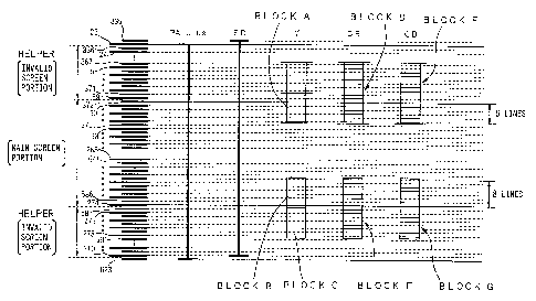
explained with reference to Fig. 1. Fig. 1 depicts fields 1 and
2 integrated into a single PAL plus image with alternating lines
of each field. The PAL plus image is segmented into an upper
invalid screen portion, a main screen portion and a lower invalid
screen portion. DCT blocks A-G represent the groups of pixels
which are DCT transformed and are depicted as rectangular blocks
superimposed on the PAL plus image. It will be noticed that the
luminance blocks are eight samples wide by eight lines long and
are twice as large as the color difference blocks, as dictated by
the 4:2:2 (Y:CB:CR) format. The blocks start at line 335 and are
repeated every eight lines for the entire PAL plus image. Thus,
the first row of luminance blocks (Y) of the main screen portion
begins with block A on line 371.
However line 371, as shown in Fig. 1, is in the upper
invalid screen portion. Thus, the first row of blocks processed
as a luminance signal (Y) overlaps into the upper invalid screen
portion and the above-described DCT distortion problem occurs.
SONY.15\3535.APP - 1 1
,.
2178185
PATENT
450100-3535
It will be noted, on the other hand, that block B, which begins
the last row of luminance blocks of the main screen portion, does
not extend into the lower invalid screen portion and does not
present a DCT distortion problem. It will also be appreciated
that the color difference blocks D, E, F and G are not effected
by the helper signal because the helper signal is processed as a
luminance block not as a color difference block. Thus, the color
difference blocks may extend into the upper and lower invalid
screen portions without any problem. Thus, in the preferred
embodiment, the problem of DCT distortion occurs with the
luminance blocks in the area of the upper invalid screen portion.
Recording Apparatus
To resolve the problem of DCT distortion, the present
invention DC shifts the helper signal. The DC shifting is
performed by the recording apparatus of the PAL plus reorder
depicted in Fig. 2 by processing circuit 6 shown in Fig. 4, as
will be explained in more detail below.
The recording apparatus of Fig. 2 has an input terminal
1 for receiving and forwarding the PAL plus signal to a Y\C
separating circuit 2. The Y\C separating circuit 2 separates the
luminance signal (Y) from the chrominance signal (C) so that
these signals can be processed separately. The separation
process is timed by a sync-separating circuit 15 which determines
SONY.15\3535.APP - 1 2
1
. , ~ 2178185
__
PATENT
450100-3535
the position of a current sample based on horizontal and vertical
sync pulses supplied with the PAL plus signal.
The separated luminance signal (Y) is forwarded to a
low pass filter (LPF) 7a that filters out high-frequency noise.
The resulting filtered luminance signal (Y) is forwarded to an
analog-to-digital converter 9a for digitization into, for
example, four bits of data, corresponding to the 4:2:2 data
format.
The chrominance signal C, separated from the luminance
signal (Y), is forwarded to the PAL signal decoding circuit 8 for
further separation into color difference signals (B-Y) and (R-Y).
It will be noted that the helper signal accompanies the
chrominance signal (C) during transmission of the PAL plus signal
and is, therefore, initially processed as a chrominance signal.
The separated color difference signals are forwarded to low pass
filters 7b and 7c for filtering out high-frequency noise and,
then, to analog-to-digital converters 9b and 9c for digitization
into two bits of color difference data for each color difference
signal. It will be appreciated that the four bits of the
luminance signal (Y), the two bits of the blue color difference
signal (CH) and the two bits of the red color difference signal
(CR) form the 4:2:2 data format of the PAL plus standard.
The analog-to-digital converters (9a - 9c) also
normalize the component signals (Y, CH, CR) as shown in Fig. 3.
SONY.15\3535.APP - 1 3 -
2178185
PATENT
450100-3535
Normalization adjusts the digital value of each pixel so that all
pixels are measured on the same scale. This ensures that the
correct color for each pixel is displayed. As shown in Figure 3,
the scale employed for the luminance signal (Y) in the PAL plus
standard ranges from a black level "16" to a white level "235" (a
mid-level "128" is considered "gray"). The color difference
signals (C$ , CR ) are adjusted to a scale with a range between
"16" and "240". It will be noted that the color difference
signals do not effect luminosity and, therefore, can exceed the
white level "235". It will also be noted that the black level
"16" is considered a pedestal level because it is above "0".
During recording, signals in the invalid screen
portions are ignored by the digital VCR 50 and must be specially
recorded. The helper signal is an important signal in the
invalid screen portions since it corrects vertical resolution
and, therefore, must be specially recorded. The WSS signal on
line 23 of the PAL plus signal (Fig. 28) indicates that a helper
signal is forthcoming and must be specially recorded. The
corresponding reference burst signal contains information
necessary to decode the helper signal after the helper signal is
extracted from the PAL plus signal and it too must be specially
recorded. Thus, the helper signal, WSS signal and reference
signal are to be specially recorded. As described, the helper
signal is recorded with the luminance signal. To that end, a WSS
SONY.15\3535.APP - 1 4
. 2178185
PATENT
450100-3535
detecting circuit 3 and a WSS\reference encoder 4 are provided
which rewrite the WSS and reference burst signals to the digital
VCR 50 for storage on a record medium.
It may be desirable to "kill" the helper signal when,
for example, the digital VCR is not equipped to process PAL plus
signals. In another instance, the helper signal bandwidth is too
wide for the digital VCR and is truncated during recording. In
these situations, the presence of the helper signal would be a
detriment because the vertical resolution would not be restored.
Thus, a helper killer mode circuit 5 instructs both the
WSS\reference encoder 4 and the processing circuit 6 to replace
the signals in the invalid screen portions (including the WSS
signal, the reference burst signal and the helper signal) with
steady-state values.
The separated signals (Y, CB, CR) are forwarded to the
processing circuit 6 for special processing. It will be noted
that the helper signal is transmitted to the processing circuit
on the blue color difference signal CB line 32.
Turning now to Fig. 4, the processing circuit 6 is
shown in more detail. The luminance signal Y is received by
input terminal 25 and sent to switch 21, which selects the
luminance signal (Y) from terminal 21a when the main screen
portions of the PAL plus signal are received. On the other hand,
the switch 21 selects the helper signal from terminal 21b during
SONY.15\3535.APP - 1 5
2178185
PATENT
450100-3535
transmission of the invalid screen portions of the PAL plus
signal. The selected signal is, then, sent to switch 22 for
further processing as will be discussed in more detail below.
The blue color difference signal (CB) and the helper
signal are received by input terminal 32 and forwarded to both
the DC level shift circuit 24 and the switch 26. The DC level
shift circuit adds a pre-determined DC offset (DC set up value)
to the received signal to match the DC offset of the luminance
signal (Y). During the invalid screen portions of the PAL plus
signal, the helper signal is input to the DC level shift circuit
and the switch 21 selects the DC level shifted helper signal from
terminal 21b. In the preferred embodiment, the normalized value
of the luminance signal (Y) is "64", and the signals in the
invalid screen portions are DC level shifted by this value.
Thus, the helper signal is extracted from the blue color
difference signal (C$) line and normalized for the luminance
signal line (Y). As a result, the helper signal in the area
between the upper invalid screen portion and the main screen
portion is normalized and DCT distortion does not occur.
During transmission of the main screen portions, the
blue color difference signal (CB) effectively bypasses the DC
level shift circuit (because switch 21 in not coupled to the DC
level shift circuit) and is output to switch 26. Similarly, the
SONY.15\3535.APP - 1 6
2178185
PATENT
450100-3535
red color difference signal (CR) received by input terminal 33 is
forwarded to switch 27.
Switches 22, 26 and 27 are each controlled by a line
counter (not shown) which keeps track of the PAL plus line number
then being received. The purpose of these switches is to
normalize certain lines in the main screen portion which give
rise to the DCT distortion. These lines are the six lines (60 to
62 and 372 to 374) in the first row of DCT blocks (i.e., block
A). Thus, switch 22 switches to the normalized value "64"
supplied to terminal 22b during transmission of lines 60 to 62
and lines 372 to 374. Similarly, switches 26 and 27 switch to
the gray level "128" during transmission of line 60 to 62 and
lines 372 to 374. By controlling the switches 22, 26 and 27 in
this manner, the levels of the luminance signal (Y) and helper
signal within the first row of DCT blocks are normalized to the
same DC set up value. Thus, the difference of levels between the
main screen portion and the upper invalid screen portion is
suppressed and DCT compression distortion (Fig. 32) is
prevented.
The signal selected by the switches 22, 26 and 27 are
forwarded to the helper killer circuit 23 which is controlled by
the helper killer signal received by input terminal 20. As
described, some digital VCR's are unequipped to handle a helper
signal or may have a frequency band that is lower than the
SONY.15\3535.APP - 1 7
2178185
PATENT
450100-3535
helper, resulting in a decrease of vertical resolution. Thus,
the helper killer circuit "kills", or cancels, the signals
transmitted during the invalid screen portions. Specifically,
the helper killer circuit 23 replaces the signals in the invalid
screen portions with normalized values. In the preferred
embodiment, the normalized values are those same values used by
switches 22, 26 and 27 such that all signals output from the PAL
plus record side processing circuit (Fig. 2) are normalized about
the same values. Therefore, the helper killer circuit
substitutes the digital value "16" for the luminance signal (Y),
digital value "128" for the color difference signals (C$ and CR),
and digital value "64" for the WSS signal present on line 23.
The luminance signal (Y), the helper signal and the
color difference signals (CB and CR) thus processed by the PAL
plus record side processing circuit are output from terminals 37,
38 and 39 as shown in Fig. 4. It will be noted that the
luminance signal (Y) line (terminal 37) now carries both the
luminance signal (Y) as well as the DC level shifted helper
signal and forwards both signals directly to input 52 of the
digital VCR 50 (Fig. 2). On the other hand, the color difference
signals (CB and CR) undergo line sequencing before being sent to
the digital VCR. This is because the digital VCR records the
color difference signals as a combination signal simply
identified as the chrominance signal (C) on the record medium.
SONY.15\3535.APP - 1 8
2178185
PATENT
450100-3535
Thus, a line sequencing circuit 10 alternately combines the color
difference signals onto a single output line and forwards these
signals to the input 53 of the digital VCR.
DIGITAL VCR
The digital VCR 50 of Fig. 2 receives the luminance
signal (Y), the helper signal and the color difference signals
CB, CR and records these signals to a record medium. The digital
VCR 50 (Fig. 2) will now be described in more detail with
reference to Fig. 5. The digital VCR receives the luminance
signal (Y) and the helper signal at input 52, the chrominance
signal (C) at input 53, audio data at input 62 and the WSS and
reference signal at input 51. As will be described in more
detail, these signals are processed by the digital VCR and
written onto a record medium via a recording head 70.
The luminance signal (Y) and the chrominance signal (C)
input at terminals 52 and 53, respectively, are forwarded to a
valid information extracting circuit 55. The valid information
extracting circuit is operable to remove extraneous information
in the invalid screen portions (including the horizontal and
vertical blanking intervals). The information transmitted during
the valid screen portion (lines 23 to 310 of field 1 and lines
335 to 622 of field 2), on the other hand, are forwarded to a
block segmenting and shuffling circuit 56.
SONY.15\3535.APP - 1 9 -
. 2178185
PATENT
450100-3535
The block segmenting and shuffling circuit receives the
valid portions of the PAL plus signal and segments the valid
portions into DCT blocks (for example, 8 x 8) in preparation for
DCT compression. The blocks are shuffled such that a mean
deviation between subsequent blocks remains substantially the
same during DCT compression. It will be appreciated that the
shuffling prevents data from being lost due to head failure or
tape damage since the blocks are more randomly disbursed on the
record medium.
The shuffled blocks are now ready for DCT compression
and are sent to the compressing circuit 57. It will be noted
that the luminance blocks (e. g., block A, Fig. 1), which extend
into the upper invalid portion, have been DCT shifted by the PAL
plus record side processing circuit 6 (Fig. 2). Thus, the
compressing circuit does not compress blocks with significantly
different values, such as when the luminance blocks are not DC
shifted. Thus, the resulting compressed blocks do not produce a
deviation in the DCT coefficients and a resulting image
distortion is prevented.
While the preferred embodiment expresses a preference
for a DCT circuit, other types of compression, of course, can be
applied. DCT compression in the preferred embodiment compresses
data by using a discrete cosine transform and a variable length
encoding algorithm. Such a compressing circuit includes: a DCT
SONY.15\3535.APP - 2 0
~~18185
PATENT
450100-3535
circuit; a quantizing circuit which quantizes the DCT transform
data coefficients; an estimator that estimates the total code
amount and determines an optimum quantizer; and a variable length
encoding circuit that compresses data corresponding to a two-
s dimensional code (such as a Huffman code).
The compressed blocks should be arranged in a frame
suitable for VCR recording. Thus, a frame segmenting circuit 58
receives the video compressed blocks and arranges them into a
frame. For example, the frame may correspond to the arrangement
shown in Fig: 23. In Fig. 21, the packs 50 to 55 are staggered
in each track of a tape medium and repeated for 10 tracks to
reduce the risk of losing data due to recording head/tape failure
by recording the blocks in a number of different places. The
multiplexor 61 (Fig. 5) arranges the video and audio sync blocks
into the packs 50-55. A more detailed explanation of the track
arrangement will be described below with reference to the tape
format.
VAUX information used to reconstruct the video portion
of the PAL plus signal is generated by a VAUX generating circuit
60 and combined with the framed video data by a VAUX adding
circuit 59. The 4~ISS and reference burst data are VAUX
information and are stored in a special pack of data called a TR
pack within the VAUX data. The time at which the VAUX data is
sent to the VAUX adding circuit is controlled by a controller 80,
SONY.15\3535.APP - 2 1 -
2178185
PATENT
450100-3535
such that the VAUX data is added at a position within the frame
(Fig. 23) reserved for VAUX data. Fig. 14B depicts a track
format employed in the preferred embodiment with the video data
sandwiched between the audio and sub-code data. Fig. 22 details
the video section of the track, wherein Fig. 23 shows the VAUX
data stored within the data section of a sync block. The
combined VAUX and video data is, then, sent to a multiplexer 61
which multiplexes the video data and other data at the
appropriate time corresponding to a position on the record
medium. Thus, the multiplexer times the recording of the video
data onto the record medium.
The audio signal is received by terminal 62 for
processing by the digital VCR. An analog-to-digital converter 63
of the preferred embodiment digitizes the audio signal but need
not compress the signal because audio data is less complex than
video data. The digitized audio data is sent to an audio
processing circuit 64 which packs the audio data according to a
predetermined sync block. An example of the audio sync block
format is shown Figs. 18 and 19A-B and will be discussed in more
detail with reference to the tape format.
Auxiliary audio data AAUX is generated by an AAUX
generating circuit 66 from information forwarded by the
controller 80 from input terminal 51 and added to the audio data
by an AAUX adding circuit 65. As in the case of the video data,
SONY.15\3535.APP - 2 2 -
2178185
PATENT
450100-3535
the combined AAUX and audio data is sent to the recording head as
determined by the multiplexer, such that the combined data is
inserted into the area of the record medium reserved for audio
data.
The multiplexer also multiplexes sub-code data onto the
record medium when the recording head is positioned over the area
reserved for the subcode data. In one embodiment, the sub-code
data includes summary information on the contents of the video
and audio data stored in an adjacent area of the record medium.
A high speed search operation accesses the recorded sub-code
data, allowing the digital VCR to quickly scan the sub-code data
without the necessity of accessing the audio or video data
directly.
The multiplexer, thus, selects the video, audio or sub-
code data for recording at the time when the record medium is at
a position corresponding to the audio, video or sub-code
positions. Before being recorded at those positions, however,
the multiplexed data is forwarded to an error correction encoding
circuit 68 for error correction in preparation for recording.
The error correction encoding adds an error correction code to
the record data. This error correction code is used on the
reproducing side of the digital VCR to determine whether the
information is valid by checking whether the reproduced area
correction code is correct.
SONY.15\3535.APP - 2 3
2178185
PATENT
450100-3535
A channel encoding circuit 69 receives the error
correction encoded signal and in one embodiment performs a "24 to
25" conversion such that the data to be recorded agrees with
digital VCR recording standards. The channel encoding circuit
also encodes the error correction encoded signal into a digital
VCR format corresponding to the partial response class 4 format.
Now, the data is ready for recording onto the record
medium by the recording head 70. The recording head digitally
records the channel encoded signal to the record medium and the
recording processing is complete. The actual signals recorded on
the record medium fall within the ranges shown by Figs. 6A to 6E.
Fig. 6A shows the WSS and reference burst signal on
line 23 of the PAL plus signal is recorded onto the record medium
with the range of values. The DC offset of the WSS signal is
shown as the first part of the signal line with a value of "64".
The following reference burst signal is shown as that part of the
signal with a DC offset of "10". It will be noted that the
reference burst signal has a lower DC offset than the DC set up
value "16".
It will be appreciated that the DC offset for the
helper signal (transmitted as a color difference signal CB, CR in
Fig. 6A) is "128". As described, the difference in the DC offset
value between the helper signal "128" and the luminance signal
"64" results in DCT distortion. With the present invention,
SONY.15\3535.APP - 2 4
2l 78185
PATENT
450100-3535
however, the difference in DC offset is corrected such that no
DCT distortion occurs.
The DC offset values for the signals occurring during
the invalid screen portions will next be discussed with reference
to Fig. 6B. In this situation, the helper killer function is
turned off such that the signals transmitted during the invalid
screen portions are sent to the digital VCR. The helper signal
has a DC offset of "64" with a fluctuating range of "108". It
will be appreciated that the maximum variation of the helper
signal is normalized to "108" by the analog-to-converter 9b (Fig.
2). From Fig. 6B, it will be seen that the helper signal is DC
shifted to the value "64" to be commensurate with the luminance
signal DC offset. Notably, there is no signal inserted in either
of the color difference signal lines in Figs. 6A and 6B as
depicted by the flat lines labelled "128" in the figures.
The main screen portions for the luminance signal (Y)
and color difference signal (CH and CR) are shown in Fig. 6C. It
will be noted that the maximum level for the luminance signal (Y)
corresponds to the white 100% reference level "235" and the
minimum value thereof corresponds to the pedestal level "16".
The white 1000 reference level defines the level at which the
corresponding image is white, whereas the pedestal level
corresponds to a color just above the black level. The color
difference signals define chrominance, not brightness, and may
SONY.15\3535.APP - 2 5
...._
2178185
PATENT
450100-3535
have a maximum value "240" greater than the white 100% reference
level of the luminance signal (Y) "235". However, both luminance
and color difference signals both share the minimum pedestal
level of "16" since darkness is an attribute of both luminance
and chrominance.
Fig. 6D shows the luminance and color difference
signals latched at "64" and "128", respectively. As described
with reference to Fig. 4, the signal lines are switched to these
mute levels for the first three upper lines of the main screen
portions in each field (i.e., first six lines of Fig. 1, lines 60
to 62 and lines 372 to 374). Muting the levels of the signal
lines also prevents DCT distortion by ensuring that the first six
lines of the main screen portion (block A, Fig. 1) have a
consistent range of values with the helper signal.
Fig. 6E depicts the reference signal on line 623 of the
PAL plus transmission. It will be appreciated that line 623 is
in an invalid screen portion and, therefore, is ignored by the
VCR unless specially recorded. The figure shows that the white
100% reference level extends from the pedestal level "16" to the
maximum luminance level of "235". This defines the value of the
luminance signal at which the corresponding image becomes
saturated with brightness and turns white.
SONY.15\3535.APP - 2 6
2178185
PATENT
450100-3535
REPRODUCING APPARATUS
Now, reproduction of the PAL plus signal which has been
processed and recorded as aforementioned, will be described with
reference to Figs. 7-9. In the preferred embodiment, the
reproducing side of the digital VCR is shown in Fig. 7 and is
symmetrical, i.e., performs the inverse of the operations of the
recording side of the digital VCR.
A reproducing head 101 reads the signals from the
record medium and transfers them to a channel decoding circuit
102. The channel decoding circuit performs the inverse function
to the channel encoding circuit 69 (Fig. 5) and, therefore, in
this embodiment performs a "25 to 24" conversion and decodes the
recorded signal in the partial response class 4 format.
An error correcting circuit 103 checks whether the
error code inserted into the recorded signal by the error
correction encoding circuit 68 (Fig. 5) is correct. If the error
code is not correct, the error correcting circuit performs error
correction, such as parity byte correction or commands the
reproducing head 101 to re-read the record medium.
A demultiplexer 104 demultiplexes the reproduced signal
corresponding to the type of reproduced data. Thus, video data
is demultiplexed and supplied to the corresponding video
circuitry, i.e., VAUX decoding circuit 106 and deframing circuit
105. Similarly, the audio data is demultiplexed and supplied to
SONY.15\353S.APP - 2 7
. 2178185
PATENT
450100-3535
AAUX decoding circuit 108 and audio processing circuit 107. The
sub-code data is demultiplexed and supplied to sub-code decoding
circuit 109.
The VAUX decoding circuit extracts the auxiliary video
data from the video signal forwarded from the demultiplexer. As
will be noted, the VAUX data includes the TR pack (Fig. 17), a
special pack which stores the WSS and reference burst signals.
This data is forwarded to a controller 120, which sends the VAUX
data to the WSS/reference encoding circuit 152 of Fig. 8. The
controller is, thus, operable to time the output of the VAUX data
when the PAL encoder 155 (Fig. 8) is encoding line 23.
The video data supplied to the deframing circuit 105 is
recorded on the tape medium in the fixed arrangement shown in
Fig. 14B. Thus, the deframing circuit is operable to deframe the
video portions from the other portions of the frame and forward
them to an expanding circuit 112.
The expanding circuit performs a function inverse to
that of the compressing circuit 57 (Fig. 5) and, thus, performs
an inverse DCT transform. The expanding circuit generates
decompressed DCT blocks (e.g., block A, Fig. 1) that are sent to
a deshuffling and deblocking circuit 113 which reorders the
blocks into a coherent image in the line and sampling order shown
in Fig. 1.
SONY.15\3535.APP - 2 8
2178185
PATENT
450100-3535
Inverse to the valid information extracting circuit 55
(Fig. 5), an information adding circuit 114 adds horizontal and
vertical sync pulses to the PAL plus signal generated by the
deshuffling and deblocking circuit. The resultant luminance (Y)
and chrominance (C) signals are sent to the reproducing apparatus
via output terminals 115 and 116.
The audio data is output from demultiplexer 104 to the
AAUX decoding circuit 108 and the auxiliary audio data is
extracted therefrom and forwarded to the controller. As with the
video data, the auxiliary audio data is forwarded to the
reproducing apparatus (not shown).
The sub-code data is demultiplexed to the sub-code
decoding circuit 109. The sub-code is extracted and forwarded to
the controller for output to the reproducing apparatus (not
shown) at a time when the subcode data is aligned with the
reproducing head.
In this manner, the digitally recorded signal is
reproduced by the reproducing side of the digital VCR of Fig. 7
and forwarded to the reproducing apparatus of Fig. 8 which will
be described in more detail below.
As aforementioned, the controller (Fig. 7) sends the TR
pack of the auxiliary video data to the WSS/reference encoding
circuit 152 of Fig. 8 at a time when the PAL encoder 155 is
encoding line 23. A counter (not shown) may be provided to count
SONY.15\3535.APP - 2 9
2178185
PATENT
450100-3535
the line number that the PAL encoder is currently processing. A
switch 156 is provided to switch to terminal 156a at the time
when line 23 is being processed such that the WSS and reference
burst data extracted by the encoder 152 from the TR pack is
output to a Y/C mixer 157. At times when the PAL encoder 155 is
processing the helper signal or main portions of the PAL plus
signal, the switch 156 is set to the terminal 156b and the output
of the PAL encoder is forwarded to the Y/C mixer 157.
The luminance signal (Y) and the helper signal which
had been recorded with the luminance signal (Y) are forwarded
directly to an input terminal 202 of a PAL plus reproduction side
processing circuit 151.
On the other hand, the chrominance signal (C) is
forwarded from the digital VCR to a line sequence interpolating
circuit 150 before being sent to the PAL plus reproduction side
processing circuit. The line sequence interpolating circuit
converts the chrominance signal (C) into color difference signals
(CH and CR). The converted color difference signals are, then,
forwarded to the PAL plus reproduction side processing circuit
for further processing. It will be appreciated that the
luminance signal (Y) and the color difference signals (C$ and CR)
are input to the PAL plus reproduction side processing circuit in
a 4:2:2 byte format, consistent with the PAL plus standard.
SONY.15\3535.APP - 3 0
~1?8185
PATENT
450100-3535
As in the case of the recording apparatus, the
reproducing apparatus also provides a helper killer mode circuit
153 for "killing", or muting, the helper signal at times when the
digital VCR is not able to process the helper signal or the
helper signal has a greater bandwidth than the VCR can process.
In such instances, the helper killer signal is sent to both the
WSS/reference encoding circuit and the PAL plus reproduction side
processing circuit indicating that both the WSS/reference burst
signal and the helper signal are to be "killed". As in the case
of recording, the luminance signal (Y) is muted to a DC level
"64" and the color difference signals (C$ and CR) are muted to
the DC level "128" in response to the helper killer signal.
The operation of the PAL plus reproduction side
processing circuit 151 will now be described in more detail and
with particular reference to Fig. 9. The luminance signal (Y)
and the helper signal are received by input terminal 202 and
forwarded to both a helper killer circuit 210 and a DC level
shift circuit 211. The DC level shift circuit removes the DC set
up value added by the recording apparatus which provides the
helper signal with a DC level commensurate with the color
difference signals.
During transmission of the helper signal, a switch 212-
is set to terminal 212b and the DC-restored helper signal is fed
onto the blue color difference signal line. At other times, for
SONY.15\3535.APP - 3 1
2178185
PATENT
450100-3535
example, when the main screen portions are processed, switch 212
is set to terminal 212a and the blue color difference signal is
fed directly to the helper killer circuit 210. In this manner,
the DC set up value added to the helper signal is removed and the
helper signal is substituted for the color difference signal (CB)
at this time. The luminance signal (Y) and the red color
difference signal (CR) are forwarded directly to the helper
killer circuit.
When the helper killer circuit is turned on, the
reproducing side processing circuit 151 "kills" the helper signal
by muting the luminance signal (Y) line. The line number can be
determined by employing a line counter (not shown) which triggers
the helper killer circuit to "kill" the helper signal on lines 24
to 59, 275 to 310, 336 to 371, and 587 to 622. The color
difference signal lines (CB and CR) are muted to the gray level
"128" at this time since no signals are to be transmitted on
those lines at this time. On the other hand, when the helper
killer circuit is turned off none of the signals are muted and
such signals are passed directly through the helper killer
circuit.
In this manner, the PAL plus reproduction side
processing circuit removes the DC level shift from the helper
signal and replaces the helper signal onto the blue color
difference signal line (CB). The luminance signal (Y) and the
SONY.15\3535.APP - 3 2
2178185
PATENT
450100-3535
color difference signals (CB and CR) are output from the PAL plus
reproduction side processing circuit to digital-to-analog
converting circuits 154a, 154b and 154c, respectively, as shown
in Fig. 8. The digital-to-analog circuits convert the video
component signals from their digital versions to analog versions
which are sent to the PAL encoder 155 for encoding.
The PAL encoder line sequences the color difference
signals into a chrominance signal (C). It will be appreciated
that the PAL encoder also inserts the reference burst signal onto
the chrominance signal line (C) when the line counter reaches
line 23.
After encoding, the luminance signal (Y) is output from
the PAL encoder and sent to a switch 156. During the
reproduction of the main screen portions, switch 156 is set to
terminal 156b and the encoded luminance signal is sent to a Y/C
mixer 157 along with the chrominance signal and the helper signal
which are forwarded directly to the Y/C mixer. The Y/C mixer
recombines the component video signals (Y) and (C) into a PAL
plus transmission signal supplied to output terminal 161. The
component video signals (Y) and (C) may also be output to a dual
terminal 158 for systems which require that the component signals
be produced separately.
In this manner, the digitally recorded signal is
reproduced and processed for transmission into a PAL plus signal.
SONY.15\3535.APP - 3 3
2178185
._
PATENT
450100-3535
TAPE FORMAT
In the above-described embodiment, reference has been
made to the tape format employed by the digital VCR. A more
detailed explanation of that tape format will now be described
with reference to Figs. l0A to 26. While the above embodiment
describes recording/reproducing PAL plus signals to and from a
tape medium, any type of record media may, of course, be
employed.
The digital VCR records tracks onto the recording
medium using a helical recording technique, wherein a rotary
magnetic head spins at an angle to the video tape which travels
along a head scan direction. The resulting track pattern shown
in Fig. l0A has tracks arranged at a slant along the tape medium.
Companion figure, Fig. lOB, shows that each track is headed by an
Insert and Track Information (ITI) header, which includes
information for aligning the data within the tracks. For
example, the ITI header indicates where the audio area, video
area and subcode areas begin.
The ITI area includes different information, as shown
in Fig. 11. The ITI area begins with a preamble which is
comprised of 1400 bits and is used as run-in when the magnetic
head reproduces a digital signal. The preamble is followed by a
Start Sync Block Area (SSA) comprised of 1830 bits to designate
the start of a sync block area. The ITI then includes 90 bits of
SONY.15\3535.APP - 3 4
2178185
PATENT
450100-3535
Track Information Area which stores information about all of the
tracks. Included in the TIA is an Application ID of a Track
(APT) of three bytes, a SP/LP flag, a reserve byte and a Pilot
Frame (PF) which represents a reference frame for the servo
system. The TIA is followed by the postamble composed of 280
bits, used to provide a margin for the track.
The remainder of the track is allocated among areas
(AREA 1, AREA 2 ... AREA n) separated by gaps (Fig. 12). As
shown in Fig. 14B, the areas may be audio, video or sub-code
areas. The ITI indicates where these areas begin/end and the
digital VCR employs the ITI to quickly find and retrieve the
desired area.
The application ID (APT) stored in the TIA designates
the different areas as being video, audio or sub-code areas. As
shown in Fig. 13, the application ID (APT) can be an hierarchy of
application IDs. With such an hierarchical structure, whole
branches including several areas of the tree can be extracted by
the digital VCR. In this manner, areas corresponding to a video
picture can be linked to each other for ease of reproducing the
video picture.
The cassette housing of the video tape preferably
includes a memory IC (MIC). The MIC of the cassette is in
communication with the digital VCR and can be employed to
remember aspects relating to all of the recorded programs on the
SONY.15\3535.APP - 3 5
2178185
,_.
PATENT
450100-3535
video tape. For example, the MIC can mark a predetermined
program, designate the reproduction order of programs, designate
a predetermined scene for reproducing a still image (i.e., a
photo), and reserve a timer record operation.
The MIC also has an application ID (APM) as shown in
Fig. 13 which is located in the high order 3 bytes of the MIC.
Similar to the Application ID of the tracks, the APM determines
the data structure of the MIC.
As an example of the application ID designating
different areas of the track, reference will be made to Figs. 14A
and 14B. When the application ID for each of the areas AP1, AP2
and AP3 are set = 000, the areas shown in Fig. 14A are designated
as audio, video and sub-code areas, respectively, as shown in
Fig. 14B. Of course, any digital representation for an
application ID can be used to indicate the data structure.
The digital VCR records the different data structures
onto the recording medium in a specific format. The AAUX, VAUX,
sub-code and MIC data relate to information about the video
picture and are written in a pack structure shown in Fig. 15. As
shown, a pack of AAUX data is composed of 5 bytes (PCO ... PC4)
with the high order byte reserved as a header (PCO) and the 4
lower bytes reserved for data. The high order 4 bits of the
header (PCO) can be used as an upper header and the lower order 4
bits of the header can be used as a lower header in an
SONY.15\3535.APP - 3 6
2178185
PATENT
450100-3535
hierarchical structure as shown in Fig. 16. Further levels can
be created by using the bits in the data area (PCl ... PC4). As
shown in Fig. 20, packs are arranged within a track in a grid
with, for example, each of packs (0 ... 8) corresponding to an
AAUX pack. Each pack is fixed in length to 5 bytes. However,
when data is written to the MIC, the pack structure has a
variable length such that the MIC can be filled to capacity to
obtain the most efficient use of the MIC.
When PCO is set to 66h (hexadecimal) as shown in Fig.
17, the data pack is regarded as a TR pack. The TR pack, as
described above, includes video picture information, such as the
WSS signal and the white 100% reference signal. The data type
section of PC1 is used to indicate which type of data follows.
This data type in the TR pack can include information on the
VBID, EDTV-2 ID on line 22 and EDTV-2 ID on line 285. Further,
the TR pack may contain any combination of the data types
including WSS data in PC2 and white 100% reference data in PC4.
Since the white 100% reference signal is transmitted during line
623 and is not recorded by the digital VCR, it is preferred that
the white 100% reference data be stored in the TR pack as well.
The audio data is stored as a sector on the recording
medium in the arrangement shown in Fig. 18. The digital VCR .
frames a preamble, an audio area and a postamble into the audio
sector along each track in the audio area (Fig. 14B) of the
SONY.15\3535.APP - 3 7 -
~~18185
PATENT
450100-3535
track. The preamble includes a run-up of 400 bits followed by
100 bits of actual preamble information, including 6 bytes of a
pre-sync block. The audio area is composed of the 14 sync blocks
(10,500 bits) of Fig. 20. That is, each audio area contains the
grid arrangement of packs shown in Fig. 20. The postamble (Fig.
18) includes 50 bits of a post-sync block and 500 bits of a guard
area; the guard area being provided to prevent the audio data
from overlapping into the next video sector.
The pre-sync block and the post-sync block are shown in
detail in Figs. 19A and 19B. The pre-sync block is shown as
having 6 bytes, including an SP/LP byte, which indicates whether
a standard play SP or a long play LP mode is selected and which
is omitted from the post-sync block of Fig. 19B. The remainder
of the pre-sync and post-sync blocks contain two sync bytes,
followed by three identification bytes (IDO, IDl and IDP).
The audio sync blocks are collected and recorded on the
recording medium with the audio area (Fig. 18) in groups of 14
sync blocks per track as shown in Fig. 20. The first nine audio
sync blocks of each group, that is, the first nine audio sync
blocks in the audio sector of a track, contain audio information,
whereas the last five sync blocks are reserved for parity
information. The first five bytes of each data sector in an
audio sync block is reserved for the 5 bytes of the AAUX pack
(Fig. 15). Recalling that the digital VCR 104 performs a "24 to
SONY.15\3535.APP - 3 8
2178185
PATENT
450100-3535
25" conversion prior to the recording of the signal, the total
bit length of the group of 14 sync blocks per track is calculated
as follows:
90 x 14 x 8 x 25 - 24 = 10,500 bytes
The audio area preferably includes the parity sectors
C1 and C2. The parity sector C1 is known as a horizontal parity
because C1 assists the digital VCR in detecting areas in the data
of the respective audio sync blocks. The parity sector C2, on
the other hand, is known as a vertical parity because C2 assists
the digital VCR to determine what will be seen as vertical errors
in all the sync blocks.
The digital VCR records the data packs, comprising the
14 audio sync blocks, onto the recording medium in the manner
shown in Fig. 21. Each of the pack numbers (0 ... 8) in Fig. 21
represent the packs (0 ... 8) in Fig. 20 which make up the data
portion of the sync block. Packs 50 to 55 are each comprised of
audio data packs and packs (a ... g) are comprised of optional
audio data. The packs are arranged in the grid shown and
repeated throughout tracks 1 to 10 in order to ensure that the
information in each data pack is recovered upon a reproducing
operation even if a portion of the data is lost due to a
mechanical failure. With this arrangement, recovery of the audio
data is ensured even if a portion of the recording medium is
corrupted.
SONY.15\3535.APP - 3 9
x'118185
PATENT
450100-3535
The video data are stored in sync blocks in a similar
fashion to the audio data as shown in Fig. 23. As in the audio
case, the video sector (Fig. 22) includes a preamble, a video
area and a postamble. Since video data is more comprehensive
than audio data, however, more video sync blocks as well as bytes
per video sync block are used in the video sector than in the
audio sector, as indicated by the bit designations in Fig. 22.
Specifically, the video sector is formed of 111,750 bits (versus
10,500 bits of the audio sector) and the guard area is formed of
925 bits (versus 500 bits of the audio guard area). The guard
area of the video data is larger than in the audio data because
video data tends to be larger than audio data and more guard bits
are required to ensure that the video data does not overlap into
adjoining areas of the record medium. The video sync block may
also include the parity sector C1 shown in Fig. 23.
The buffers in Fig. 24 are stored on a track of the
record medium within the video area of the video sector. Since
each buffer (BUFF 0 to BUFF 26) contains five video sync blocks
the total of 27 buffers yields 135 video sync blocks in each
track. As in the audio area, horizontal parity C1 and vertical
parity C2 are provided to ensure that the digital VCR will
accurately reproduce the stored video data. The first two sync
blocks, the first five bytes of each buffer, and the sync block
after the last buffer (BUFF 26) may be left blank to provide
SONY.15\3535.APP - 4 0
-- 2178185
PATENT
450100-3535
margins so that the reproducing head of the digital VCR 104 can
be accurately aligned with the appropriate video sync blocks.
As with the audio data, the video data is converted by
a "24 to 25" conversion process by the digital VCR before being
recorded on the recording medium. After the conversion, the
total bit length of the video sector is as follows:
90 x 149 x 8 x 25 \24 = 111,750 bits
Subcode data is also recorded on the recording medium
in a data pack arrangement. As shown in Fig. 25, the subcode
sector includes 1200 bits of a preamble, 1200 bits of a subcode
area and 1325 or 1200 bits of a postamble. Unlike the audio and
video areas, the preamble of the subcode sector does not have a
pre-sync block and the postamble of the subcode area does not
have a post-sync block. This is because the subcode sector is
frequently rewritten for indexing during a search, and updating
the pre-sync and post-sync blocks each time during the search is
time consuming. The subcode sector preferably contains 12
subcode sync blocks with each subcode sync block including 5 pre-
sync bytes, 5 data bytes and parity bytes C1 as shown in Fig. 26,
thus forming a 12-byte sync block.
The sub-code data is also converted by a "24 to 25"
conversion process of the digital VCR and the total bit length of
the sub-code sector is as follows:
12 x 12 x 8 x 25/24 - /1200 bits
SONY.IS\3535.APP - 4 1
~~78185
PATENT
450100-3535
Thus, the present invention provides a
recording/reproducing apparatus and method for digitally
recording a PAL plus signal to a record medium and reproducing
the signal therefrom without DCT distortion. It is to be
understood that, within the scope of the appended claims, the
invention may be practiced otherwise than as specifically
described herein.
SONY.15\3535.APP - 4 2