Language selection

Search

Patent 2178276 Summary

Third-party information liability

Some of the information on this Web page has been provided by external sources. The Government of Canada is not responsible for the accuracy, reliability or currency of the information supplied by external sources. Users wishing to rely upon this information should consult directly with the source of the information. Content provided by external sources is not subject to official languages, privacy and accessibility requirements.

Claims and Abstract availability

Any discrepancies in the text and image of the Claims and Abstract are due to differing posting times. Text of the Claims and Abstract are posted:

  • At the time the application is open to public inspection;
  • At the time of issue of the patent (grant).
(12) Patent: (11) CA 2178276
(54) English Title: TRAILER HITCH
(54) French Title: ATTELAGE DE REMORQUE
Status: Term Expired - Post Grant Beyond Limit
Bibliographic Data
(51) International Patent Classification (IPC):
  • B60D 01/40 (2006.01)
  • B60D 01/00 (2006.01)
  • B60D 01/04 (2006.01)
(72) Inventors :
  • RUSSELL, GREGORY A. (United States of America)
(73) Owners :
  • GREGORY A. RUSSELL
(71) Applicants :
  • GREGORY A. RUSSELL (United States of America)
(74) Agent: SMART & BIGGAR LP
(74) Associate agent:
(45) Issued: 2000-11-14
(22) Filed Date: 1996-06-05
(41) Open to Public Inspection: 1996-12-08
Examination requested: 1997-10-29
Availability of licence: N/A
Dedicated to the Public: N/A
(25) Language of filing: English

Patent Cooperation Treaty (PCT): No

(30) Application Priority Data:
Application No. Country/Territory Date
08/477,403 (United States of America) 1995-06-07

Abstracts

English Abstract

An improved trailer hitch which can be used to more easily attach a trailer to a towing vehicle by simply engaging a horizontal coupling shaft in a latch assembly, and closing the latch. The trailer hitch comprises six main components: a yoke assembly, a latch assembly, a transverse horizontal coupling shaft, a connector bar, a trailer yoke and a pivot bolt. The yoke assembly provides for rotation about the vertical axis, the latch assembly provides for rotation about the transverse horizontal axis, and the pivot bolt for rotation around the longitudinal horizontal axis. A trailer can be easily attached to a towing vehicle by placing the transverse horizontal shaft in the latch assembly, and closing and fastening the latch.


French Abstract

Attelage de remorque amélioré, qui peut être utilisé pour atteler plus facilement une remorque à un véhicule remorqueur en engageant un arbre d'accouplement horizontal dans un ensemble de loquet, et en fermant le loquet. L'attelage de remorque comprend six composants principaux : un ensemble de fourche, un ensemble de loquet, un arbre d'accouplement horizontal transversal, une barre de raccordement, une fourche de remorque et un axe d'articulation. L'ensemble de fourche permet une rotation autour de l'axe vertical, l'ensemble de loquet permet une rotation autour de l'axe horizontal transversal, et l'axe d'articulation permet une rotation autour de l'axe horizontal longitudinal. Une remorque peut être attelée facilement à un véhicule remorqueur en plaçant l'arbre horizontal transversal dans l'ensemble de loquet, et en fermant et sécurisant le loquet.

Claims

Note: Claims are shown in the official language in which they were submitted.

THE EMBODIMENTS OF THE INVENTION IN WHICH AN EXCLUSIVE
PROPERTY OR PRIVILEGE IS CLAIMED ARE DEFINED AS FOLLOWS:
1. A trailer hitch comprising:
(a) a yoke assembly comprising a yoke section and a latch
section, said latch section comprising a vertical opening;
(b) a latch assembly comprising a latch pivot bolt, and two
latch plates pivotally connected on either side of the yoke section by the
latch pivot bolt to the yoke assembly;
-7-

(c) a transverse horizontal coupling shaft, the extremal ends
of the horizontal coupling shaft dimensioned to fit into the vertical opening
in the latch section, and be secured by the latch plates;
(d) a connector bar, said transverse coupling shaft passing
transversely and horizontally through the connector bar, wherein the
transverse horizontal coupling shaft can be securely and pivotally connected
to the latch assembly by placing the horizontal transverse coupling shaft in
the vertical opening of the latch section, rotating the latch plates down over
the horizontal transverse coupling shaft, and securing the latch plates in
position with a hitch pin;
(e) a trailer yoke, said connector bar pivotally connected to
the trailer yoke by a vertical pivot bolt; and
(f) a longitudinal pivot bolt for longitudinally and pivotally
connecting the trailer yoke to a trailer.
2. The trailer hitch of claim 1, wherein the trailer yoke is a
flat U-shaped trailer yoke.
3. The trailer hitch of claim 1, wherein the trailer yoke has
a plate section and an arm section, said arm section comprising two spaced
apart arms, each arm having a forward section and a rearward section, and
wherein the distance between the forward sections of the spaced apart arms
is less than the width of the plate section.
4. The trailer hitch of claim 1, wherein the latch pivot bolt,
the vertical pivot bolt and the longitudinal pivot bolt have been heat
treated.
-8-

5. The trailer hitch of claim 4, wherein the latch pivot bolt,
the vertical pivot bolt and the longitudinal pivot bolt have been heat treated
to meet the strength requirements of SAE grade 8.
6. The trailer hitch of claim 1, wherein the transverse
horizontal coupling has been heat treated.
7. The trailer hitch of claim 6, wherein the transverse
horizontal coupling is characterized by having a Brinnell hardness number
between 269 and 321, inclusive.
8. A trailer hitch assembly comprising:
(a) a longitudinal pivot bolt for pivotally attaching a first
yoke to a trailer hitch;
(b) a vertical pivot bolt for pivotally attaching the first yoke
to a connector bar;
(c) a transverse horizontal shaft, for pivotally attaching the
connector bar to a second yoke, wherein the second yoke has a vertical
opening adapted to receive the transverse horizontal shaft; and
(d) at least one latch plate, each latch plate being pivotally
connected by a latch pivot bolt to the second yoke such that the at least one
latch plate can be rotated to secure the transverse horizontal shaft in the
vertical opening of the second yoke.
9. The trailer hitch of claim 8, wherein the at least one
latch plate comprises two latch plates, wherein both latch plates can be
-9-

rotated to secure the transverse horizontal shaft in the vertical opening of
the second yoke.
10. The trailer hitch assembly of claim 9, wherein the first
yoke is a flat U-shaped yoke.
11. The trailer hitch assembly of claim 9, wherein the trailer
yoke has a plate section and an arm section, said arm section comprising
two spaced apart arms, each arm having a forward section and a rearward
section, and wherein the distance between the forward sections of the
spaced apart arms is less than the width of the plate section.
12. The trailer hitch assembly of claim 9, wherein the latch
pivot bolt, the vertical pivot bolt and the longitudinal pivot bolt have been
heat treated.
13. The trailer hitch assembly of claim 12, wherein the latch
pivot bolt, the vertical pivot bolt and the longitudinal pivot bolt have been
heat treated to meet the strength requirements of SAE grade 8.
14. The trailer hitch assembly of claim 9, wherein the
transverse horizontal coupling has been heat treated.
15. The trailer hitch assembly of claim 14, wherein the
transverse horizontal coupling is characterized by having a Brinnell
hardness number between 269 and 321, inclusive.
16. The trailer hitch assembly of claim 9, further comprising
a hitch pin for insertion through holes in the latch plates and through holes
in the second yoke to secure the latch plates in a closed position.
-10-

I7. A trailer hitch for coupling a trailer to a towing vehicle
comprising:
(a) a first U-shaped yoke having a base plate and two spaced
apart arms extending forwards from the base plate;
(b) a longitudinal pivot bolt inserted in a hole in the base
plate, the head of the longitudinal pivot bolt being forward of the base
plate, for
connecting the first U-shaped yoke to a trailer;
(c) a vertical pivot bolt, inserted vertically through holes in
the arms of the base plate, connecting the first U-shaped yoke to a connector
bar;
(d) a horizontal coupling shaft, inserted transversely through
a hole in the connector bar, left and right portions of the horizontal
coupling
shaft extending on either side of the connector bar;
(e) a second U-shaped yoke having two spaced-apart parallel
arms, said parallel arms each having a vertical opening therein, such
vertical openings being adapted to engage the portions of the horizontal
coupling shaft extending on either side of the connector bar; and
(f) at least one latch plate pivotally attached to the second
U-shaped yoke, said at least one latch plate configured such that when the
horizontal coupling shaft is engaged in the vertical openings in the parallel
arms of the second U-shaped yoke, the at least one latch plate can be
rotated over the horizontal coupling shaft to secure the horizontal coupling
shaft in position.
-11-

18. The trailer hitch of claim 17, wherein the at least one
latch plate comprises two latch plates, wherein both latch plates are
pivotally attached to the second U-shaped yoke, and can be rotated over the
horizontal coupling shaft to secure the horizontal coupling shaft in position.
19. The trailer hitch of claim 18, wherein the longitudinal
pivot bolt and the vertical pivot bolt have been heat treated.
20. The trailer hitch of claim 18, wherein the longitudinal
pivot bolt and the vertical pivot bolt have been heat treated to meet the
strength requirements of SAE grade 8.
21. The trailer hitch of claim 18, wherein the arms of the
first U-shaped yoke are flat and parallel to each other.
22. The trailer hitch of claim 18, wherein the spaced arms of
the first U-shaped yoke have a rearward portion and a forward portion, and
the distance between the spaced apart arms is greater in the rearward
portion than in the forward portion.
23. The trailer hitch of claim 18, wherein the transverse
horizontal coupling has been heat treated.
24. The trailer hitch of claim 18, wherein the transverse
horizontal coupling is characterized by having a Brinnell hardness number
between 269 and 321, inclusive.
-12-

Description

Note: Descriptions are shown in the official language in which they were submitted.


_ ,;~ .
CA 02178276 1999-12-23
TF,ATT FR HITCH
BACKGROUND
Field of the Invention. .
The present invention is a three-way swivel action trailer hitch.
Back~'round of the Invention. a
Trailer hitches are used to provided rotatabl~e mechanical
coupling between a towing vehicle and a trailer. The mechanical coupling is
preferably rotatable around all three axes, to allow the trailer to be towed
around turns, up and down inclines, and over uneven pavement.
Trailer hitches having three-way rotatable coupling between
the towing vehicle and the trailer are known in the art. For example, U.S.
Patent No. 4,711,461, issued on December 8th.t 19.87 to. F'rg~ discloses a
three-axis trailer hitch comprising a first U-shaped yoke supporting a hinge
pin rotating about the transverse horizontal axis, a second U-shaped yoke
supporting a hinge pin rotating about the vertical axis, and a rotatable joint
providing rotation about the longitudinal horizontal axis. U.S. Patent No.
2,027,499 to Tully discloses a trailer hitch comprising a turntable disc
providing rotation about the longitudinal horizontal axis, and a U-shaped
yoke supporting a king pin rotating about the transverse horizontal axis,
and a swivel bolt providing rotation about the vertical axis. Other trailer
hitches are disclosed in U.S. Patent Nos. 2,457,885; 2,871,030; 3,730,557;
3,843,164; 4,200,306; and 4,548,423.
-1-

2178276
SUMMARY OF THE INVENTION
The present invention is an improved trailer hitch which can be
used to more easily attach a trailer to a towing vehicle. In the present
invention, the trailer can be attached to the towing vehicle simply by
engaging a horizontal coupling shaft in a latch assembly, and closing the
latch.
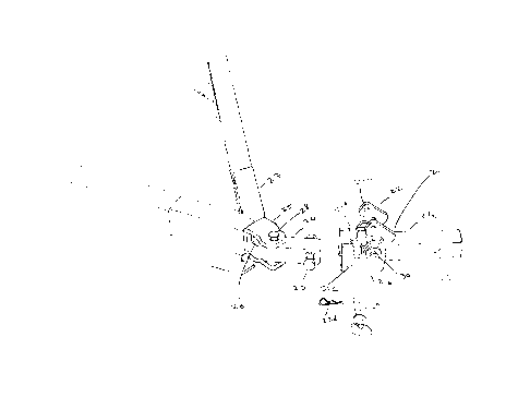
As shown in Figure 1, the trailer hitch of the present invention
comprises six main components: a yoke assembly, latch plates, a transverse
horizontal coupling shaft, a connector bar, a trailer yoke assembly and a
pivot bolt. The trailer yoke assembly provides for rotation about the vertical
axis, the transverse horizontal shaft provides for rotation about the trans-
verse horizontal axis, and the pivot bolt for rotation around the longitudinal
horizontal axis.
A trailer can be easily attached to a towing vehicle by placing
the transverse horizontal shaft in the yoke assembly, and closing and
fastening the latch.
It is the object of the present invention to provide a three-way
swivel action trailer hitch that can be used to easily and securely attach a
trailer to a towing vehicle.
This object, and other objects of the present invention are
described in greater detail in the detailed description of the invention, the
appended drawings and the attached claims.
-2-

2178276
BRIEF DESCRIPTION OF THE DRAWINGS
Figure 1 is a perspective view of the trailer hitch, just before
the transverse horizontal shaft is engaged in the latch assembly.
Figure 2 is a side view of the present invention, with the
transverse horizontal shaft engaged in the latch assembly.
Figure 3 is an exploded side view of the trailer-side portion of
the trailer hitch, including the pivot bolt, the trailer yoke and the
connector
bar.
Figure 4 is a schematic diagram of the horizontal coupling
shaft.
Figure 5 is a schematic diagram of a trailer yoke having flat,
parallel arms, and the connector bar.
DETAILED DESCRIPTION OF THE INVENTION
Figure 1 is a schematic diagram of the present invention. The
trailer hitch of the present invention is comprised of six main components:
yoke assembly 21, latch plates 22, horizontal coupling shaft 23, connector
bar 24, trailer yoke 25 and pivot bolt 26.
Yoke assembly 21 comprises a rectangular yoke section 21a and
a latch section 21b. Yoke section 21a includes a hole 19 which is used to
attach the yoke to a towing vehicle, using a retainer pin (not shown). Yoke
assembly also includes hitch pin 29, which is used to hold latch plates 22 in
position over coupling shaft 23.
-3-

2178276
Latch plates 22 are pivotally attached to latch section 21b by
pivot bolt 30. Horizontal coupling shaft 23 passes through connector bar 24,
such that it will fit into the vertical openings 21d of latch section 21b. At
its opposite side, coupling shaft 23 is secured to yoke section 21b by closing
latch plates 22 over coupling shaft 23, and passing hitch pin 29 through
holes 22c in latch plates 22 and holes 21c in latch section 21b. Hairpin
cotter pin 22d prevents hitch pin 29 from slipping out of position.
Latch plates 22 could be two separate latch plates, as shown in
Figure 1, or could be two latch plates which have been integrally connected
to form a single unit. Latch plates 22 could also be manufactured as a
single unit.
The opposite end of connector bar 24 is attached to U-shaped
trailer yoke 25 by vertical pivot bolt 28. Rotation about vertical pivot bolt
28 provides for left-right rotation of the trailer with respect to the towing
vehicle about the vertical axis. Yoke 25 is attached to trailer bracket 27 by
longitudinal pivot bolt 26. Trailer yoke 25 can pivot around longitudinal
pivot bolt 26, thus providing the hitch with rotation about the horizontal
longitudinal axis.
Figure 2 is a side view of the present invention, with horizontal
coupling shaft 23 engaged in latch assembly 22. Figure 2 provides a clear
view of pivot bolt 26. Figure 3 is an exploded view of the trailer-side of
Figure 2, showing pivot bolt 26, flat washer 26a, flange nut 26b, vertical
pivot bolt 28 and locking nut 28a. Figure 3 also shows connector bar 24,
-4-

~~1 ~g276
which comprises hole 33, hole 31, and sleeve 32. When the trailer hitch is
assembled, horizontal coupling shaft 23 is inserted through hole 33, sleeve
32 is inserted in hole 31, and vertical pivot bolt 28 is inserted in sleeve
32.
Vertical pivot bolt 28 is then secured with locking nut 28a. The length of
sleeve 32 is slightly greater than the height of connector bar 24, such that,
when yoke 25 is secured to connector bar 24, it is free to rotate around the
vertical axis.
Figure 4 is a schematic diagram of horizontal coupling shaft 23.
To maximize the strength of the trailer hitch, bolts 26, 28 and 30 are pre-
ferably selected from bolts which have been heat treated to meet the
strength requirements of SAE (Society of Automotive Engineers) grade 8.
Horizontal coupling shaft 23 is preferably manufactured from material
which has been heat treated such that it has a Brinell Hardness Number
between 269 and 321 (inclusive).
Yoke 25 is shown in Figures 1 and 2 as having a relatively
wide plate section 25a compared to the distance across the end portion of its
forward arm section 25b holding vertical bolt 28. The greater width for the
plate section allows for the use of large diameters for the shaft and head of
pivot bolt 26, and provides a mechanical advantage with respect to the
weight of the trailer's tongue applied against pivot bolt 26. However, the
present invention could also be implemented using a flat-armed, U-shaped
yoke, as shown in Figure 5. Figure 5 shows flat-armed, U-shaped yoke 50
pivotally connected by pivot bolt 28 to connector bar 24.
-5-

21713276
Plate 27a in Figure 3 is an, e.g., one-inch thick plate that is
welded into position as shown. The length of the smooth section of pivot
bolt 26, i.e., the section between the threaded section of pivot bolt 26 and
the head of pivot bolt 26, is slightly longer than the sum total of the thick-
nesses of plate 27a, washer 26d, and plate section 25a of yoke 25. The
additional length of pivot bolt 26 is required to allow the rotation of the
trailer hitch around the longitudinal axis.
The foregoing disclosure of embodiments of the present inven-
tion has been presented for purposes of illustration and description. It is
not intended to be exhaustive or to limit the invention to the precise forms
disclosed. Many variations and modifications of the embodiments described
herein will be obvious to one of ordinary skill in the art in light of the
above
disclosure. The scope of the invention is to be defined only by the claims
appended hereto, and by their equivalents.
-6-

Representative Drawing
A single figure which represents the drawing illustrating the invention.
Administrative Status

2024-08-01:As part of the Next Generation Patents (NGP) transition, the Canadian Patents Database (CPD) now contains a more detailed Event History, which replicates the Event Log of our new back-office solution.

Please note that "Inactive:" events refers to events no longer in use in our new back-office solution.

For a clearer understanding of the status of the application/patent presented on this page, the site Disclaimer , as well as the definitions for Patent , Event History , Maintenance Fee  and Payment History  should be consulted.

Event History

Description Date
Inactive: Expired (new Act pat) 2016-06-05
Inactive: Late MF processed 2010-06-03
Letter Sent 2009-06-05
Small Entity Declaration Determined Compliant 2008-04-28
Small Entity Declaration Request Received 2008-04-28
Inactive: IPC from MCD 2006-03-12
Inactive: Late MF processed 2003-06-04
Letter Sent 2002-06-05
Grant by Issuance 2000-11-14
Inactive: Cover page published 2000-11-13
Inactive: Final fee received 2000-08-10
Pre-grant 2000-08-10
Letter Sent 2000-02-10
Notice of Allowance is Issued 2000-02-10
Inactive: Approved for allowance (AFA) 2000-01-24
Amendment Received - Voluntary Amendment 1999-12-23
Inactive: S.30(2) Rules - Examiner requisition 1999-11-22
Inactive: Status info is complete as of Log entry date 1998-01-06
Letter Sent 1998-01-06
Inactive: Application prosecuted on TS as of Log entry date 1998-01-06
All Requirements for Examination Determined Compliant 1997-10-29
Request for Examination Requirements Determined Compliant 1997-10-29
Application Published (Open to Public Inspection) 1996-12-08

Abandonment History

There is no abandonment history.

Maintenance Fee

The last payment was received on 2000-05-26

Note : If the full payment has not been received on or before the date indicated, a further fee may be required which may be one of the following

  • the reinstatement fee;
  • the late payment fee; or
  • additional fee to reverse deemed expiry.

Patent fees are adjusted on the 1st of January every year. The amounts above are the current amounts if received by December 31 of the current year.
Please refer to the CIPO Patent Fees web page to see all current fee amounts.

Fee History

Fee Type Anniversary Year Due Date Paid Date
Request for examination - small 1997-10-29
MF (application, 2nd anniv.) - small 02 1998-06-05 1998-05-25
MF (application, 3rd anniv.) - small 03 1999-06-07 1999-05-27
MF (application, 4th anniv.) - small 04 2000-06-05 2000-05-26
Final fee - small 2000-08-10
MF (patent, 5th anniv.) - small 2001-06-05 2001-06-01
MF (patent, 7th anniv.) - small 2003-06-05 2003-06-04
Reversal of deemed expiry 2009-06-05 2003-06-04
MF (patent, 6th anniv.) - small 2002-06-05 2003-06-04
MF (patent, 8th anniv.) - small 2004-06-07 2004-05-10
MF (patent, 9th anniv.) - small 2005-06-06 2005-05-30
MF (patent, 10th anniv.) - small 2006-06-05 2006-04-18
MF (patent, 11th anniv.) - small 2007-06-05 2007-03-26
MF (patent, 12th anniv.) - small 2008-06-05 2008-04-28
MF (patent, 13th anniv.) - small 2009-06-05 2010-06-03
MF (patent, 14th anniv.) - small 2010-06-07 2010-06-03
Reversal of deemed expiry 2009-06-05 2010-06-03
MF (patent, 15th anniv.) - small 2011-06-06 2011-03-25
MF (patent, 16th anniv.) - small 2012-06-05 2012-04-10
MF (patent, 17th anniv.) - small 2013-06-05 2013-05-29
MF (patent, 18th anniv.) - small 2014-06-05 2014-06-03
MF (patent, 19th anniv.) - small 2015-06-05 2015-02-27
Owners on Record

Note: Records showing the ownership history in alphabetical order.

Current Owners on Record
GREGORY A. RUSSELL
Past Owners on Record
None
Past Owners that do not appear in the "Owners on Record" listing will appear in other documentation within the application.
Documents

To view selected files, please enter reCAPTCHA code :


To view images, click a link in the Document Description column. To download the documents, select one or more checkboxes in the first column and then click the "Download Selected in PDF format (Zip Archive)" or the "Download Selected as Single PDF" button.

List of published and non-published patent-specific documents on the CPD .

If you have any difficulty accessing content, you can call the Client Service Centre at 1-866-997-1936 or send them an e-mail at CIPO Client Service Centre.


Document
Description 
Date
(yyyy-mm-dd) 
Number of pages   Size of Image (KB) 
Description 1996-09-12 6 198
Claims 1996-09-12 6 180
Abstract 1996-09-12 1 20
Drawings 1996-09-12 5 40
Description 1999-12-22 6 200
Claims 1999-12-22 6 183
Representative drawing 1998-05-07 1 13
Representative drawing 2000-10-24 1 7
Acknowledgement of Request for Examination 1998-01-05 1 178
Reminder of maintenance fee due 1998-02-08 1 111
Commissioner's Notice - Application Found Allowable 2000-02-09 1 166
Maintenance Fee Notice 2002-07-02 1 177
Late Payment Acknowledgement 2003-06-19 1 165
Maintenance Fee Notice 2009-07-19 1 171
Late Payment Acknowledgement 2010-06-14 1 163
Fees 2003-06-03 1 29
Fees 2003-06-03 1 31
Correspondence 2000-08-09 1 38
Fees 1998-05-24 1 35
Fees 2001-05-31 1 28
Fees 1999-05-26 1 32
Fees 2000-05-25 1 30
Fees 2004-05-09 1 31
Fees 2005-05-29 1 27
Fees 2006-04-17 1 25
Fees 2007-03-25 1 28
Correspondence 2008-04-27 2 54
Fees 2010-06-02 1 33
Fees 2010-06-02 1 34
Fees 2011-03-24 1 35