Language selection

Search

Patent 2178569 Summary

Third-party information liability

Some of the information on this Web page has been provided by external sources. The Government of Canada is not responsible for the accuracy, reliability or currency of the information supplied by external sources. Users wishing to rely upon this information should consult directly with the source of the information. Content provided by external sources is not subject to official languages, privacy and accessibility requirements.

Claims and Abstract availability

Any discrepancies in the text and image of the Claims and Abstract are due to differing posting times. Text of the Claims and Abstract are posted:

  • At the time the application is open to public inspection;
  • At the time of issue of the patent (grant).
(12) Patent: (11) CA 2178569
(54) English Title: FINGER RING
(54) French Title: BAGUE
Status: Expired and beyond the Period of Reversal
Bibliographic Data
(51) International Patent Classification (IPC):
  • A44C 9/00 (2006.01)
(72) Inventors :
  • ZELLER, JOSEPH (United States of America)
  • RUBIN, BRUCE (United States of America)
(73) Owners :
  • ASTORIA JEWELRY MFG. CO., INC.
  • JEWELASTORIA, INC.
(71) Applicants :
  • ASTORIA JEWELRY MFG. CO., INC. (United States of America)
  • JEWELASTORIA, INC. (United States of America)
(74) Agent: SMART & BIGGAR LP
(74) Associate agent:
(45) Issued: 2006-03-21
(22) Filed Date: 1996-06-07
(41) Open to Public Inspection: 1996-12-08
Examination requested: 2002-06-04
Availability of licence: N/A
Dedicated to the Public: N/A
(25) Language of filing: English

Patent Cooperation Treaty (PCT): No

(30) Application Priority Data:
Application No. Country/Territory Date
08/480,368 (United States of America) 1995-06-07

Abstracts

English Abstract


A finger ring structure, particularly for rings having precious
stones set therein, which has improved placement and removal
characteristics and with a more comfortable fit even when sized in
accordance with measurements as used in the prior art. The ring
comprises a standard section of a cylinder, with an inner surface
and an outer surface, and is modified such that the circumferential
edges of the inner surface are inwardly rounded and wherein the
rounded edges of the inner surface, adjacent a setting or
ornamental section are provided with a bombs configuration, i.e.,
an extended curved section, with a substantially arced inner
surface configuration.


Claims

Note: Claims are shown in the official language in which they were submitted.

THE EMBODIMENTS OF THE INVENTION IN WHICH AN EXCLUSIVE
PROPERTY OR PRIVILEGE IS CLAIMED ARE DEFINED AS FOLLOWS;
1. A finger ring structure, which has improved placement and removal
characteristics, comprising a cylindrical section with an ornamental external
section
thereof, the ornamental section comprising a channel into which stones are
inserted,
said cylindrical section having a continuous inner surface, said channel
having a
closed base formed by said inner surface, said ring having an outer surface,
each of
said inner surface and said outer surface having respective circumferential
edges,
wherein the circumferential edges of said inner surface are inwardly rounded
and
wherein the rounded edges of said inner surface, adjacent the ornamental
section, are
formed into a bombé configuration.
2. The finger ring of claim 1, wherein said bombe configuration is positioned
on said ring, extending from an interior aperture of the ring for
accommodation of a
finger therein, in an upward and outward direction, relative to the aperture
and finger
accommodated therein, whereby the bombe configuration extends away from the
outside of the finger and away from the adjacent juxtaposition of said finger
with
adjacent one or more fingers.
9

Description

Note: Descriptions are shown in the official language in which they were submitted.


~~'~85~9
FINGER RING
Field of the Invention
This invention relates to ornamental finger ring structures and
particularly to rings having precious stones set thereon.
eACRaRO~ of T~ INV~NTIOx
Ornamental rings worn on fingers, such wedding bands, engagement
rings and the like are made of precious metals such as gold,
silver or platinum, and are configured to snugly fit onto
fingers, With sized measurement. The interiors ~,f t~,ora ,.
are generally shaped as cylinder sections, in order to conform
with the finger on which it is placed. The exterior of the
cylindrical section of a ring, which is positioned adjacent the
palm of a wearer, is not otherwise ornamented, to avoid
irritation of the hand and in any event, it is not normally as
visible. The remaining portions of the ring (except for simple
bands) are adorned with carvings, etchings, integrally molded on
and soldered elements, set gems with settings, and the like.
The most expensive ring jewelry is provided with setting elements
and precious stones such as diamonds set therein. Common setting
elements included raised prongs which engage portions of the
precious stones (e.g. the girdle of a commonly cut diamond) or
1

2:~'~8569
channels formed in the band itself, with internal notches which
engage the girdle or edges of the stone or stones. Clear glue or
adhesive is used with inexpensive rings of a costume jewelry
type, to hold ersatz stones in place. Rings with channels and
internal notches for accommodation of precious gems, are
generally made with the channels having open bases, in the ring
metal beneath the set stones, to permit full light transmission
through the stones to enhance brilliance thereof.
A problem with many, if not all snugly fitting rings is the fact
that the finger on which the ring (having a circular cylindrical
section configuration) is placed, does not actually have a fully
co-fitting circular cross section). As a result, rings, even if
properly sized, do not fit with a fully proper accommodation
(though the soft flesh of the finger will accommodate to the
circular ring). These rings are usually difficult, without
lubrication, to put on or remove, particularly across the hard
bony knuckle of the finger and with the high friction contact
between the skin and the ring.
It is accordingly an object of the present invention to provide a
ring structure which facilitates emplacement on and removal of
the ring from a finger.
It is a further object of the present invention to provide such
ring structure with a filled in base below channel set precious
2

2~~85~9
stones.
It is a still further object of the present invention to
provide such ring structure which does not result in discomfort or
irritation of adjacent fingers.
These and other objects, features and advantages of the
present invention will become more evident from the following
discussion and drawings in which:
SHORT DESCRIPTION OF THE DRAWINGS
Figure 1 is a side view of a ring of the prior art, shown
as taken from a section of a cylinder;
Figure 2 is a cross section view of the ring of Figure 1
taken along line 2-2;
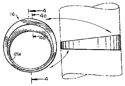
Figure 3 is a side view of a ring made in accordance with
the present invention, shown as taken from a section of a cylinder;
Figure 4 is a cross section view of the ring of Figure 3
taken along line 4-4
Figure 4a is an enlarged cross section view taken along
the line 4a-4a of Figure 3;
Figure 5 is an isometric view of the prior art ring of
Figures 1 and 2, shown as being placed on (or taken off) a finger;
3
76725-1

~I78~~~
Figures 6 and 7 depict the rings of Figures 1 (prior art) and 3
(of the present invention), as positioned on fingers (shown in
cross section); and
Figure 8 is an isometric view of the ring of the present
invention of Figures 3 and 4, shown as being placed on (or taken
off) a finger.
BUMMARY OF THE INVENTION
Generally the present invention comprises a ring structure,
particularly for rings having precious stones set therein, which
has improved placement and removal characteristics and with a
more comfortable fit even when sized in accordance with
measurements as used in the prior art. In accordance with the
present invention, a ring, comprising a standard section of a
cylinder, with an inner surface and an outer surface, is modified
such that the circumferential edges of the inner surface are
inwardly rounded and wherein the rounded edges of the inner
surface, adjacent a setting or ornamental section are provided
with a bombe configuration, i.e., an extended curved section,
With a substantially arced inner surface configuration.
DETAILED DESCRIPTION OF TH$ INVENTION
In a preferred embodiment of a ring having a channel setting
4

2178~~9
configuration for precious stones, the bombs is solid throughout,
without the base apertures which are present in rings of the
prior art.
While the edges of the inner surface of prior art rings have been
radiussed to eliminate sharp edges, and gouging of fingers, they
have not been inwardly curved. The introduction of curved edges
in ring thicknesses, generally requires an increase in the ring
thickness to accommodate the curve dimensions. However, increase
of ring thickness is undesirable since it overly interferes with
adjacent fingers and is either uncomfortable or irritating to the
wearer. In accordance with the present invention, the edges of
the inner surface of the ring in the areas adjacent the palm and
the adjacent fingers are curved to a full radius, without
increase of ring thickness, but with the curvature and thickness
of the ring gradually increasing from the point at which the ring
no longer touches or is proximate the adjacent fingers) towards
the ornamental portion or setting portion thereof, i.e., crown of
the ring. The curvature increases, with a bombs configuration at
the crown with a substantially complete arced inner surface of
ring at such portion. With the edges of the inner surface of the
ring being fully curved, as described, the ring, with the same
internal diameter as a prior art ring, literally rolls on or off
the finger.
The thickened bombe configuration also permits channel placement
5

21'~~~~~__
of stones while maintaining a full inner surface curvature.
Prior art rings cannot be radiussed adjacent the stone settings
without unsightly deformation of the stone setting area or
without sufficient setting room, absent excessive lateral
extension which interferes with adjacent fingers. Furthermore,
such prior art rings are made with bottom apertures in the
channels whereby such bombs formation is not. It has however
been discovered that closure of the base, with bombs formation
does not affect perceived brilliance as compared to rings of the
prior art.
For ring measurement purposes it is preferred that a small
centrally positioned circumferential portion of the inner surface
of the ring remains flat.
DESCRIPTION OF THE DRAWINGS AND THE PREFERRED EMBODIMENT
With reference to the drawings, in Figure 1, a typical prior art
ring 10 is shown as a section lla of a cylinder 11 (shown in
dotted lines). The circular inner surface 12 of the ring 10 has
relatively sharp edges 12a and 12b and is essentially flat in
cross section as shown in Figure 2. When ring 10 is placed on or
removed from a finger 1 (as shown in Figure 5) there is a large
area of frictional contact between the inner surface 12 and the
finger 1, which makes movement up and down the finger (for
placement and removal) difficult. Tilting of the ring 10, as
6

~1'~~j~~
shown by the arrows, to facilitate placement or removal, is limited
because of the edges 12a and 12b, which are very close to the
ffinger.
Ring 110 of the present invention shown in Figures 3, 4,
4a, 7 and 8, has an inner surface 112, with a smallest diameter
being the same diameter as that of prior art ring 10 (i.e., same
ring size), but with inner surface edges 120a and 120b being curved
away from an inserted finger, as seen in Figures 4 and 8. Only
segment 129 remains as a circumferential flat surface. Thus, with
reference to Figure 8, only a small area of the inner surface of the
ring 110 is in frictional contact with finger 1. Furthermore,
tilting of the ring 110, with placement and removal on and from the
finger, causes the curved edges 120a and 120b of the ring 110 and
bombe portion 118 to engage and roll across the skin of the finger 1.
In a further comparison between the prior art ring 10 of
Figures 1, 2, 5 and 6 and the ring 110 of the present invention,
shown in Figures 3, 4, 4a, 7 and 8, it is noted that adding an inner
curvature to ring 10 at the setting area 10a, without the bombe
configuration of the present invention, results in a limitation of
space for insertion of stones 20a-e, in the channel 15 (i.e., the
channel is narrowed). As a result, in order to set the stones
20a-e, it is necessary to add additional width 16 (shown in dotted
lines) to properly accommodate the stones 20a-e, which
7
76725-1

~~~8~~9
increased width would interfere with adjacent fingers 2 and 3.
With the bombs configuration lib in the ring 110 of the present
invention, additional space is provided for the insertion of stones
200a-a into channel 115, which has had its dimensions increased for
such accommodation but in a direction which will not interfere with
adjacent fingers 2 and 3, as shown in Figure 7.
It is understood that the above description and drawings are
illustrative of the present invention and that changes may be made
in the ring structure, ornamentation and materials without
departing from the scope of the present invention, as deined in the
following claims.
8

Representative Drawing
A single figure which represents the drawing illustrating the invention.
Administrative Status

2024-08-01:As part of the Next Generation Patents (NGP) transition, the Canadian Patents Database (CPD) now contains a more detailed Event History, which replicates the Event Log of our new back-office solution.

Please note that "Inactive:" events refers to events no longer in use in our new back-office solution.

For a clearer understanding of the status of the application/patent presented on this page, the site Disclaimer , as well as the definitions for Patent , Event History , Maintenance Fee  and Payment History  should be consulted.

Event History

Description Date
Time Limit for Reversal Expired 2010-06-07
Letter Sent 2009-06-08
Grant by Issuance 2006-03-21
Inactive: Cover page published 2006-03-20
Inactive: Final fee received 2006-01-03
Pre-grant 2006-01-03
Notice of Allowance is Issued 2005-10-24
Letter Sent 2005-10-24
Notice of Allowance is Issued 2005-10-24
Inactive: Approved for allowance (AFA) 2005-10-06
Amendment Received - Voluntary Amendment 2005-07-18
Inactive: S.30(2) Rules - Examiner requisition 2005-01-17
Amendment Received - Voluntary Amendment 2003-06-05
Letter Sent 2002-07-02
Inactive: Status info is complete as of Log entry date 2002-07-02
Inactive: Application prosecuted on TS as of Log entry date 2002-07-02
All Requirements for Examination Determined Compliant 2002-06-04
Request for Examination Requirements Determined Compliant 2002-06-04
Appointment of Agent Requirements Determined Compliant 2001-10-16
Inactive: Office letter 2001-10-16
Revocation of Agent Requirements Determined Compliant 2001-10-16
Letter Sent 2001-09-24
Inactive: Office letter 2001-07-19
Application Published (Open to Public Inspection) 1996-12-08

Abandonment History

There is no abandonment history.

Maintenance Fee

The last payment was received on 2005-05-26

Note : If the full payment has not been received on or before the date indicated, a further fee may be required which may be one of the following

  • the reinstatement fee;
  • the late payment fee; or
  • additional fee to reverse deemed expiry.

Please refer to the CIPO Patent Fees web page to see all current fee amounts.

Owners on Record

Note: Records showing the ownership history in alphabetical order.

Current Owners on Record
ASTORIA JEWELRY MFG. CO., INC.
JEWELASTORIA, INC.
Past Owners on Record
BRUCE RUBIN
JOSEPH ZELLER
Past Owners that do not appear in the "Owners on Record" listing will appear in other documentation within the application.
Documents

To view selected files, please enter reCAPTCHA code :


To view images, click a link in the Document Description column. To download the documents, select one or more checkboxes in the first column and then click the "Download Selected in PDF format (Zip Archive)" or the "Download Selected as Single PDF" button.

List of published and non-published patent-specific documents on the CPD .

If you have any difficulty accessing content, you can call the Client Service Centre at 1-866-997-1936 or send them an e-mail at CIPO Client Service Centre.


Document
Description 
Date
(yyyy-mm-dd) 
Number of pages   Size of Image (KB) 
Representative drawing 1998-03-09 1 7
Abstract 1996-09-23 1 19
Description 1996-09-23 8 253
Claims 1996-09-23 1 36
Drawings 1996-09-23 3 63
Cover Page 1996-09-23 1 16
Description 1996-07-11 8 303
Drawings 1996-07-11 3 101
Claims 2005-07-18 1 32
Drawings 2005-07-18 3 68
Representative drawing 2005-11-03 1 10
Cover Page 2006-02-16 1 37
Reminder of maintenance fee due 1998-02-10 1 111
Courtesy - Certificate of registration (related document(s)) 2001-09-24 1 136
Acknowledgement of Request for Examination 2002-07-02 1 193
Commissioner's Notice - Application Found Allowable 2005-10-24 1 161
Maintenance Fee Notice 2009-07-20 1 171
Correspondence 2001-06-06 11 352
Correspondence 2001-07-19 1 14
Correspondence 2001-10-16 1 12
Correspondence 2001-10-16 1 15
Correspondence 1996-07-11 18 627
Fees 2003-06-03 1 31
Fees 2000-06-07 1 42
Fees 2001-06-06 11 404
Fees 2002-06-04 1 29
Fees 2004-06-01 1 35
Fees 2005-05-26 1 28
Correspondence 2006-01-03 1 24
Fees 2006-04-24 1 38