Note: Descriptions are shown in the official language in which they were submitted.
2 ~ 78~a2
APPARATUS AND METHOD FOR CONTROLLING THE
ROTARY AIR~OCKS IN A COAL PROCESSING SYSTEM
The Government of the United States of America has certain
rights in this invention pursuant to contract No. DE-FC22-9OPC8966
5 awarded by the U. S . Department of Energy .
Field o~ the Tnv~nt; on
The present invention relates to a coal processing system, and
more particularly, to improvements preventing the j amming of rotary
airlocks in a coal processing system.
B~k~rollnd of th~ Tnv~ntion
Certain geographical areas have large deposits of coal.
However, the coal may be low-rank coal requiring a beneficiation,
namely, to remove moisture and impurities and thus improve the BTU
to weight ratio; and for this reason, ~he coa~l is treated in coal
processing systems.: In these systems, the coal is conveyed into
(and out of ) a pres6ure chamber having a controlled gaseous
composition, wherein the coal is subjected to increased
temperatures and pressures
Rotary airlocks are an important part o~. the coal processing
system 10 (as shown in Fig. 1). These r-otary airlocks 11 and 11'
are installea at the entrance and exit, respectively, oft the
pressure chamber (or fluidized bed) 12 for transferring the coal
between success~ve~p~oces'sing operations, maintaining the pressure
and temperature differential therebetween, and keeping gaseous
compositions within the pressure chamber~ 12 and may include the
airlock 11 ' with controlled feed rate and the free flow airlocks
11. Thus, the rotary airlocks are a major, and important,
components in coal processing syste~s
Unfortunately, however, the conventional rotary airlocks
30 currently belng used (in coal processlng systems) tend to jam. The
jamming is caused by hard materials found in the coal being
proce6sed, as for example, lumps of solid rocks which become stuck
between the rotating vanes and the stationary walls of the rotary
airlocks. When jamming occurs, the entlLe continuous coal
processin-g system ~Lust be stopped ln order to clear or unclog the
jammed airlock As somewhat schematically shown ln Fig. 2,
~ _ , . . . _
~ ~ 78682
cleaning of the jammed airlock usually is a manual, time consuming
and expensive operation; and permanent damage to the rotary airlock
and its motor and drive systems may occur.
Although the prior art of rotary airlocks is well developed,
5 nevertheless, all of these prior art rotary airlocks are subject to
j amming or clogging.
For instance, U.S. Patent ~o 4,076,150~ describes a rotary
airlock with blades adjustable in such a manner so as to maintain
the pressure seal. U.S. Patent Nos. 4,7~0,273, 4,599,8~9 and
5,165,434 describe rotary airlocks powered by an electric motor
(schematically shown in Fig. 3). U.S. Patent Nos. 5,122,259 and
5 ,178, 733 teach a rotary airlock with means for indicating and
controlling the speed of rotation. However, none of these prior
art patent references is concerned with preventing jammings of the
airlocks.
In an effort to solve this problem, mechanical sensors have
been suggested~ in the field to detect jams and, once detected,
mechanical switches provide for a reverse rotation to clean the
rotary airlock. Disadvantageously, the mechanical switches are
unable to~.quickly sense jams and to take corrective actions in
order to adequately prevent solid j ams
Therefore, a more ~eliable and less expensive means for
quickly detecting when a rotary airlock (in a coal processing
system) may jam, and for quickly preventing the jam and unclogging
the rotary airlock, would be very desirable.
Sl ~ry of th~ Tnyention
It is, therefore, an object of the present invention to
provide a coal processing system having improved control of its
rotary airlocks, thereby avoiding costly shut-downs of the overall
system.
It is further object of the present invention to provide a
coal processing system, wherein t~le rotary airlocks are continually
monitored for sensing even a partial jamming; and wherein the
direction of rotation of the vanes In the rotary alrlocks is
quickly reversed, thereby clearing a partial jamming and avoiding a
complete (or solid) j amming
2l 7a6s-2
It i8 still another object of the present invention to provide
a coal processing system having a means for continually monitoring
the instantaneous current of a motor and drive system which rotates
the vanes of the airlock, and further having a controller for
5 reversing the motor when the instantaneous motor current exceeds a
predetermined value.
Although the present invention may find an application in any
material processing apparatus requiring rotary airlocks when
handling any abrasive, granular, powdered material, crushed ore,
10 etc., it finds its particular utility in a coal processing system,
wherein coal particles are passed into and out of a processing
vessel through inf low and outf low rotary airlocks, each of which
includes a plurality of circumferentially-spaced vanes rotating
within a chamber and mounted on a shaft driven by a variable-speed
15 = reversible electric motor f~ft~rr;31 ly of the chamber (the motor
having a rated operating current) and wherein each of the rotary
airlocks is subject to jamming by lumps of solid rock or other hard
materials found in the coal.
In accordance with the teachings of the present invention, the
20 improved coal processing system includes a means for continually
monitoring the instantaneous current of the motor driving the
rotary airlock. The instantaneous motor current is compared to the
rated operating current of the motor to obtain a differential
signal; and a controller means reverses the motor when the
25 differential slgnal has exceeded a predetermined threshold value.
As a result, even a partial jamming in the rotary airlock is
quickly sensed, the rotary airlock is quickly cleared, and complete
jams and costly shut-downs of the overall system are avoided.
In a preferred embodiment, the quick clearing may b~ performed
30 according to one of the following methods
a The controller means reverses the orlglnal direction o~
the rotation of the vanes of the rotary airlock and contirlues this
reversed direction until the next jamming situation occurs
b The controller means reverses the original direc~ion o~
35 rotation of the vanes of the rotary airlock ~or a short ~ ime, and
then continues the rotation in its original direc~ion.
2 ~ 7~6~2
c. The controller means reverses the original direction of
rotation of the vanes of the airlock several times in momentary
succession, and then continues the rotation in its original
direction .
Preferably, the controller means provides a ~soft'~ start for
reversing the motor. ~ ~
These and other objects of the present invention will become
apparent from a reading of the following specification, taken in
conjunction with the enclosed drawings.
Brief Description of th~ Draw;nas=
Fig. 1 is a schematic view of a coal processing system showing
the relative location of rotary airlocks in the thermal and cooling
process according to the prior art.
Fig. 2 shows a manual cleaning of the jammed airlock,
according to the prior art.
Fig. 3 is a side elevational view of a rotary airlock of the
prior art with certain parts broken away and sectioned.
Fig. 4 is a side elevational view of a rotary airlock of the
present invention corresponding substantially to Fig. 3, but
showing schematically a motor with a motor current sensing means
Fig. 5 is a cross-section of the rotary airlock of Fig. 4
taken along lines 5-5 thereof.
Fig. 6 is a block-diagram of the motor control sensing means
of the rotary airlock used in the coal processing system oE the
present invention.
Figs. 7A - 7D show schematically (in cross-section of the
airlock of the present invention) steps af forming the jamming
situation and automatic "unj amming" of the airlock
Petai led Description of the Preferred ~ o~im~nt
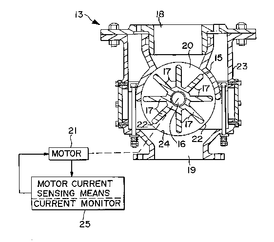
Referring to Figs. 4-6 and 7A-7D, an airlock 13 includes a
cylindrical housing 15, a shaft 16 extending therethrough, and a
plurality of circumferentially-spaced vanes 17 mounted on a f irsL
portion 16 ~ of the shaft 16 and secured thereon The vanes 17 have
respective working edges which desirably have a minimum clearance
relative to the houslng 15 Alternately, a blade may be secured to
the vane 17 and extend outwardly therefrom to provlde minimum
~ 2 ~ 78~2
clearance relative to the housing 15. An inlet 18 and outlet 19
communicate with a chamber 20 defined by the housing 15. The inlet
18 carries the coal 14 into the chamber 20, and the outlet l9
carries the coal away from the chamber 20. An electric motor 21 is
5 located outside of the housing 15 in electrical and mechanical
contact with a second portion 16" of the shaft 16 extending
outwardly of the housing 15.
Some clearance 22 is provided between working edges 23 of the
vanes 17 and interior walls 24 of the chamber 20 to allow for
rotation of the shaft 16 and the vanes 17. The clearance 22 has a
tendency for jamming by hard materials, for instance, lumps of
solid rock, found in the coal stock. Most common is jam occurring
at the pinch point 22 ' where the vane 17 comes into close proximity
with the sealing surface created by the housing 15. Furthermore,
15 multiple pockets which are defined between the shaft 16, housing 15
and adjacent vanes 17, also may cause jamming of the airlock 13 by
hard mate~ials, as best shown in Figs. 7A and 7B
It is important to correct the undesirable jamming at its
initial stage before a complete jam has been developed. Since the
20 complete jam may be developed from a partial jam relatively fast,
it is important to sense the partial jam substantially immediately
It was found that anything longer than a very short delay after
jamming of the airlock occurred would in-turn cause lock-up
internally to right-angIe gear reducer 34 that transmits power from
25 the electric motor 21 to the shaft 16 of the rotary airlock The
lock-up of the right-angle gear reducer 34, if happens, requires
removal of the chain that connects the drive motor to the gear
reducer 34 to corr-ect the problem.
For this reason, the motor 21 is provided with a current
30 monitor 25 for c~n~ i nll~l ly monitoring current used by the motor, as
best shown in Figs 4-6. Since motor cu~rrent is directly
proportional with motor torque, even partial jams cause a
substantial and immediate increase in the current to be drawn by
the motor 21. The essential feature of the present invention --
35 the monltoring of the instantaneous motor current --- provld~s a
higher sensitiYity of the c=urrent monitor 25 ,to partial jams. This
2 ~ 7J682
reduces the number of complete jams that need to be corrected, by
correcting them in the initial (partial) jam stages.
Once the current monitor 25 detects the increasing current
drawn by the motor 21/ indlcating thereby a partial jam of the
S airlock 13, a controller 26 automatically reverses rotation of the
motor 21, thereby reversing rotation of the shaft 16 and vanes 17.
This automatic action unjams the airlock 13 before the complete jam
matures out of the partial jam, as best shown in Figs. 7C and 7D.
~s best shown in Fig. 6, the controller 26 includes a timing
relay 29 and a dup3i~xing relay 30 and operates as follows:
The variable speed drive receives a run command f rom the plant
control system (typically a programmable logic controller). The
current monitor 25, and particularly the current sensor 24, which
is an integral part of the current monitor 25, monitors one of the
15 motor leads 28 and compares the current to an adjustable set point
(typically set between 12596 and 15096 of motor full load current) by
a comparing means 33 which is also an integral part of the current
monitor 25. While the ~otor current reaches or exceeds the set
point, a signal is applied to a timing relay 29. If the signal is
20 applied to the timing relay 29 for a period greater than its
adjusted value (typically 0.5 seconds), a signal is applied to the
duplexing relay 30. The dupIexing relay 30 then switches the
direction signal to the variable speed drive The variable speed
drive will then decelerate and then accelerate in the new
25 direction. The motor status signal is fed back to the plant
control system to provide verification of selected motor state (run
or stop). Contacts of the duplexing relay 30 are monitored by the
plant control system in order to Aetect and notify the operator
upon the initiation of a direction change. Monitoring the
30 duplexing relay 30 with the plant control system also provides
6hutdown of the motor 21 in the event of a j am that does not clear
(detected upon occurrence of a rapid succession of direction
changes). The above variable speed drive can be replaced with a
reversing motor starter (preferably a soft starting type) ~or
35 airlock applications that are not used for controlling feed rate
2 1 78682
It will be appreciated by those skilled in the art that the
motor will draw a certain level of current when it is free running
and not jammed at all. When the airlock is completely jammed, and
the vanes are not rotating at all, the motor 21 will draw a
substantially higher level of current. It is effective to take
automatic unj amming action when the current drawn by the motor has
risen to a leveI e~ual to or greater than the average between free
running current level and the completely jammed current level,
thereby indicating a partial jam existing and the threat of a
complete (or solid) j am developing .
For example, if the normal current reading for a particular
airlock with a particular motor (in a given application) is two
(2 . 0) amps in the unjammed free-running condition, then a reading
of three point five (3.5) amps or higher may indicate a partial
jam, and a reading of five ~5) amps may indicate a camplete jam.
In this particular example, an instantaneous current of the
motor is continually compared with a rated operating current (2 . 0
amps~ of the motor to obtain a differential signal. If the
differential signaI exceeds a predetermined threshold value (1.5
amps) indicating a partial jam, then the motor is reversed in one
of three operating patterns discussed herein to clear the jamming
occurred. As best shown in Figs. 7C ana 7D, after reversing the
motor, the obstruction falls further into the pocket between
airlock vanes (blades) 17, so that it clears the jam.
It will be appreciated by those skilled in the art that the
example discussed herein is intended for illustration purposes
only, and a variety of other current readings as well as
predetermined threshold values for each particular coal processing
system are possible_ =
A~oth~r essential feature of the invention is that the
controller 2~ takes advantage of the variable speed capabilities of
the motor 21, and controls these capabilities in order to provide a
~soft" start=for reversing the motor by ramping up the power
supplied to the motor 21 from zero to the final operating level.
This allows the motor 21 to accelerate to its final operating speed
over a relatively short period of time. If the power is supplied
2 ~ 7~6~
B
to the motor 21 abruptly (and not ramped up, as in the present
invention) the motor 21 would have a "hard" start resulting in
increased stresses in the motor 21 and the airlock 13
Accordingly, the "soft" start of the motor 21 in the present
5 invention reduces wear, as well as the time consuming and expensive
maintenance =on the coal processing system.
The following three methods (or "strategies") of cleaning jams
(partial or complete) can be provided by the controller 26 upon a
reading of the motor current increase:
1. For an airlock capable of rotating in either direction, a
simple reversal of the direction of the rotation. For example, in
an airlock application where the airlock has a top inlet and a
bottom outlet, the vanes can usually rotate in either direction
without operational impact on the plant.
2. For an airlock which may need to rotate in only one
direction, a reversal of the direction of rotation for only a short
period of time, and then automatically returning the airlock to
forward (or original) rotation.
3. Reversal of the direction of rotation several times in
quick succession, in order to unjam in a rocking type of motion,
and then return the airlock to the proper permanent (or original)
direction of rotation.
obviOusly, many modifications may be made without departing
from the basic spirit of the present invention.
. For example, at least two different configurations for
reversing the airlocks upon sensing a jam may be used, both
configurations using motor current to detect the jam The major
difference between the two configurations is that a reversing motor
starter (rather than a variable frequency drive~ is used for
airlock applications that free-flow material through the airlock
The variable frequency ~speed) drive is used with applications that
control a feed rate
The present invention can be manufactured and used for any
size rotary a~rlock. With different sizes of airlocks and motors,
di~erent current read;ngs would be used to indicate partial jams
and ~omplete jams, and to undertake unjamming strategies
2 i 7~2
Differ~nt applications for the eame size airlock with the same size
motor may also require different triggering current readings, and
this can be established by empirical observation in each case
Accordingly, it will be appreciated by those skilled in the
5 art that within the scope ~f one aE~ended- claims, the present
invention may be practiced other than has been specifically
descrlbed herein.