Note: Descriptions are shown in the official language in which they were submitted.
, 2 1 78782
FLAT CABLE AND BARING PINCERS
BACKGROUND OF THE INVENTION
The present invention relates to a flat cable comprising at least one series of wires
arranged to convey electrical power and/or information in the form of electrical or
optic signals, these wires being coated with a layer of synthetic insulating or
protective material.
It also relates to pincers for locally baring said flat cable.
DiHerent types of nat cables have been developed by manufacturers and are
designed for numerous specific ~"" " ,s such as for example for elevator
cables, These cables are now beginning to be used in increasingly broader fieldsand notably in that of traditional electrical installation of buildings for ,u,ure~iu,lal or
private use.
The advantage of flat cables is that they enable the use of quick connection
systems by perforation or .ii~pldcellle"l of the insulator at any place on thesecables. The extension and uel~e,. " " ~ of domestic automation systems merely
increase the field of application of flat cables.
Flat cables do on the other hand present drawbacks, notably that of not being able
to be run in the tubes fitted in the walls, generally used for traditional electrical
il I ' " " 15.
. .
To overcome this drawback, diHerent solutions are envisageable, such as running
the cables in a skirting board or trunking or designing a cable which can be folded
on itself to present the form of a round cable able to be inserted in a tube of circular
cross-section. The solution of the skirting board or trunking is generally well
accepted for premises for ~,urèss;~,"al use, omces, labc),d~ulie~, etc., but is not
greatly dppleeidLed for residential use.
Furthermore, whatever the solution adopted, the flat cablê presents a difficulty to
pass corners. The relative rigidity of the insulating layer gives rise to a diHficulty both
for flat angles, where the axis of the cable changes, and for protruding angles where
~ ~ 2 1 78782
the axis of the cable remains d~ tl.idbl) in the same plane.
Whether it be to pass corners, to house the electrtcal wires of a flat cable in a flush-
mounted sheath or sometimes to faciiitate fitting of apparatuses such as switches,
current sockets or the like, the fitter has to bare this cable over a given length. This
operation is often performed manually with rudimentary tools such as a knife blade
or another sharp tool, The result does not always conform to safety and quality
standards, and the conductors may be nicked or damaged.
The document DE-C-941,070 relates to a flexible flat cable, the internal space of
whose sheath contains a spare channel. The presence of this channel is designed
for fitting additional conductors, and in no way enables baring of the insulating
sheath ~a) surrounding the conductors.
SUMMARY OF THE INVENTION
The object of the present invention is to overcome all these drawbacks by achieving
a flat cable able to be bared easily and very precisely, without the conductors being
able to be damaged.
This object is achieved by the flat cable according to the invention, ~ dld~ ed in
that it comprises at least one hollow longitudinal protuberance extending along the
whole of the cable on at least one of its lateral sides, this protuberance comprising a
continuous axial cavity designed to be slit to facilitate baring of the insulating layer
over a given section of cable.
According to one fëature of the invention, the cavity is separated from the adjacent
wire by a joining bridge, which can be torn off after the protuberance has been slit
followed by separation of the two flanks of said protuberance.
According to a preferred ~",bo.li"lt:"~, said cavity is filled with a friable stuffing
material.
This friable stufffing material is preferably inserted between the wires and the layer of
insulating or protective material.
- 2 1 7~782
This object is also achieved by pincers to locally bare the flat wire defined above.
BRIEF DESCRIPTION OF THE DRAWINGS
The present invention and its main advanta3es will be better understood with
reference to the followin3 description of several ~ o~li"l~, of the nat cable
described as non-restrictive examples only and to the accompanying drawings in
which:
- Fi~ure 1 represents a p~,~j,e-.'i:c view of a section of flat cable according to the
invention,
- Fi3ure 2 represents a pc~ e- i/C view of another ~",bOdilln:lll of a flat cable
accordin3 to the invention,
- Fi3ure 3A represents a transverse sectional view of the cable l~ a~.lled by
fi3ure 1,
- Fi3ure 3B illustrates a phase of removal of the layer of insulating material on a
section of the cable accordin3 to figures 1 and 3A
- Figure 3C represents a perspective view of the flat cable accordin3 to the
invention whose insulating layer has been removed over a 3iven section,
- Figure 4 represents a transverse sectional view of another ,:,"L,o.li",~"l of the flat
cable according to the invention which constitutes an alternative ~IIlI,u.lil,,~lll of the
cable according to fgure 2,
- Fi3ure 4 represents a transverse sectional view of another ~"lbodi",~"l of the flat
cable accordin3 to the invention which constitutes an alternative e,,,budi,,n~ of the
cable accordin3 to h~ure 2,
- Fi3ure 5 represents a transverse sectional view illustrating an alternative
constructive c,,"L,odi",e"l of the flat cable of fi3ure 4
- Figures 6 7 and 8A represent transverse sectional views illustrating various
~ 2178782
.~ 4
t,lll~odi",~"l, of a nat cable according to the invention,
- Figure 8B illustrates a phase of removal of the layer of insulating material on a
section of the cable as ~ ,S~ d'l by figure 8A,
- Figures 9 and 10 represent two other alternative ~",Lo~i",c",lb of the flat cable
according to the invention,
- Figures 11A and 11B represent ,~ ,~,e,,';~ly p~,b~,e, l;~c and elevational views of
pincers for baring the hat cable accordina to the invention, these pincers being in the
open position, and
- Fisures 12A and 12B represent respectively pellb,oe~.t;~c and elevational views of
pincers for baring the flat cable according to the invention, these pincers beina in the
closed position,
- Figures 13 and 14 are identical views to fiaure 4 o~ two other alternative
_"~b~.li",~:"l:. of the cable accordina to the invention.
DETAILED DESCRIPTION OF THE PREFERRED EMBODIMENT
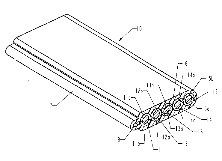
Fiaure 1 represents a p~:, b~.e~ c view of a section of flat cable accordina to a hrst
~",bodi"Idlll. This cable 10 comprises for example hve electncal wires 11, 12, 13,
14, and 15 arranaed side by side in a ribbon braid. These wires each comprise a
central conductor 11a, 12a, 13a, 14a and 15a, which may be of the sinale-wire ormulti-strand type, surrounded by an insulatina sheath respectively 11b, 12b, 13b,
14b and 15b. These insulated and juxtaposed electrical wires are coated with a
layer of insulatina or protective synthetic material 16 which defines the flat cable.
The originality of this cable compared to traditional cables is that it comprises a
longitudinal swelling or protuberance 17 which extends continuously over the whole
length of the cable, on at least one of its lateral sides. This longitudinal protuberance
17 is hollow and comprises a continuous axial cavity 18 so that the protuberance is
presented as a tube. As will be explained further on, the presence of this hollow
protuberance greatly facilitates barina of the cable by "peeling" off the insulating
layer over a section defined between two notches made by means of the pincers
described hereaher.
. 2 1 78782
Figure 2 represents a p~ dU'h/C view of a section of flat cable ~,ul~ o~ g to
another e",l,o.li",~"~. This cable 20 comprises for example a first series of five
electrical wires 21, 22. 23, 24 and 25 designed for lldll~ of electricat power
to supply an apparatus or a power system, and a second series of two wires 26 and
27 designed to convey illru,,,,dliull for exampie in the form of electrical or optic
signals. As an example, the wires 26 and 27 can form a pair of twisted wires for a
telephone link. The two series of wires form two ribbon braids 20a and 20b coated
with a layer of insulating synthetic material 28. In the example ~ "~d, the
electrical wires 21, 22, 23, 24 and 25 each comprise a single-wire or multi-strand
central conductor 21a, 22a, 23a, 24a and 25a surrounded by an insulating sheath
respectively 21b, 22b, 23b, 24b and 25b. It can be noted that in this t,l,Lodi",~lll,
the electrical wires are not juxtaposed and that a space is arranged laterally
between them. It should also be noted that between the insulating layer 28 and the
insulating sheaths 21b, 22b, 23b, 24b and 25b.there is a stufffing material 29 whose
function will be specified further on,
The i"ru", " , transfer wires 26 and 27 may be bare or insulated conductors and
they are also surrounded by a stuffing material 30 which is situated between thecoating layer of synthetic material 28 and said wires, The layer 28 is continuous and
surrounds bûth the electrical wires 21 to 25 and the information transfer wires 26
and 27. A zone of smaller thickness or joining bridge 31 joins the two parts of the
cable which ~,u~ Julld to the two ribbon braids 20a and 20b. As previously, the nat
cable comprises a longitudinal protuberance 32 which extends continuously, for
example on one of the lateral sides of this cable. This protuberance is hollow and
comprises a continuous cylindrical cavity 33 which enables the insulating layer to be
easily removed over a section of cable defined between two transverse notches 40.
Figures 3A and 3B illustrate more specifically the local baring mode of a cable as
le~ ,s~,.llèd by figure 1. This operation is performed in several phases. The first one
consists in bounding the zone to be bared by two transverse notches made at eachend of this zone by means of suitable pincers as l~ sè"k:d in figures 11 and 12.
These notches 40 are preferably straight and have a depth a which ~,ull~ ol1ds to
the half-difference of thickness between the insulating layer 16 and the insulating
sheaths 11b, 12b, 1 3b, 14b and 15b of the electrical wires 11, 12, 13, 14 and 15.
~: : 2 1 78782
The second phase consists in slitting the longitudinal protuberance 17 lon~itudinally
over the section defined between the two transverse notches 40. In the course ofthis phase, at least one slit 41 is made in the protuberance. This slit extends to the
inside of the continuous axial cavity 18 of the protuberance 17. It can be made in
the plane of symmetry of the cable or in one of the flanks of the protuberance.
Preferably a double slit will be made sy~ le~ !y in both flanks of the
protuberance .
The third phase consists in "peeling off' the cable on the chosen section by pulling
the two flanks of the protuberance 17 separated by one or more slits 41 apart. This
operation consists in tearing the joining zone 42 which separates the cavity 18 from
the wire 11 and, if this is the case, from the joining zones of small thickness
separating the electrical wires from one another when the latter are not perFectly
r~se~ As soon as these ~oining zones have been torn off the insulating layer
can be removed cleanly on the zone defined between the transverse slits 40 (hgure
3C).
Figure 3C represents the cable 10 previously bared over a certain section with aview to fitting an electrical apparatus (not ~ st",I~d) thereto which can be
coupled to the cables by suitable means, for example self-baring connectors. Theelectrical wires 11, 12, 13, 14 and 15 are removed from the insulating layer over a
certain section 50. The cable is designed to be housed in a trunking which protects
it the electrical apparatus being mounted overlapping this trunking.
Fi3ure 4 represents a sectional view illustrating another r:l"l,odi",e"~ of a nat cable
10 which differs from the cable ,~p,cDellI~d by figure 2 notably by the fact that the
cavity arranged inside the longitudinal protuberance 17 is Rlled with a stuffng
material 60. This cable comprises in addition like the one in figure 2, a first series of
five electrical wires 21 22, 23 24 and 25 arranged side by side in a ribbon braid and
a second series of two wires 26 and 27 also anranged in a ribbon braid. Between the
insulating sheaths of the wires and the layer of insulating material 16 filling has been
performed by means of a stuffing material identical to that which fills the cavity of the
protuberance. This material is preferably of fnable nature so that it can be easily
removed as soon as the insulating layer has been removed.
~ 2 1 78782
In this t:lllbu-lillle:llL, the electrical wires 21, 22, 23, 24 and 25 are appreciably
juxtaposed and the stufflng material 60 fills zones of ~ U~ 9y triangular cross-section each bounded by two faces of two juxtaposed wires and the inner surface of
the insulating layer 16. In the same way, stufflng material 60 surrounds the wires 26
and 27.
To bare this cable, the procedure is as before beginning by making two transverse
slits and then slitting the lon~itudinal protuberance 17 in a direction parallel to the
axis. The slit may be single or double depending on the tool used. The stufflng
material contained in the cavity of the longitudinal protuberance can be removedeasily as it has the particularity of crumbling and not adhering to the insulating layer.
As soon as the joining bridge 61 has been torn away, the insulating layer opens like
a bivalve shell. The part of the cabie containing the wires 26 and 27, in the form
Lud, is bared like the cable of figure 1. This baring can be facilitated in
different ways as will be specified further on.
Figure 5 shows a cable 10 similar to that of figure 4, but wherein the wires 21, 22,
23, 24 and 25 are spaced apart. They are thereby completely buried in the stufflng
material 60. The stufflng material contained inside the cavity 18 of the protuberance
17 is also therefore the same as that which coats the above-mentioned wires, which
eliminates the joining bridge 61 which can be seen in figure 4. ~ikewise, the wires 26
and 27 are surrounded by stufling material 60.
The consequence of eliminating this joining bridge is that opening of the "bivalve
shell" type takes place i"""e-lidl~ly as soon as the protuberance 17 is slit, at least
as far as the ribbon braid of wires 21, 22, 23, 24 and 25 is concerned.
Figures 6, 7, 8A, 8B, 9 and 10 illustrate alternative constructive ~IllL,odi~ ,lt:, of the
cable 10 according to the invention. To simplify the views, the first ribbon braid only
comprises three wires, but it is obvious that the same principles apply to ribbon
braids having a different number of wires.
In particular, the cable 10 of figure 6 comprises three wires 11, 12, 13 coated with a
stufflng material and surrounded by an insulating sheath 16. It comprises two
longitudinal protuberances 17 arranged on each side of the ribbon braid on its two
lateral sides. Removal of the insulator is simplified when the two protuberances are
~. . 2 1 78782
slit lon~itudinally. The two protuberances 17 can be hollow or filled with stumng
material.
Figure 7 illustrates an alternative ~,llbo.li",~"l of a flat cable 10 with two ribbon
braids of wires, ._..,.e- liJ~,y 21, 22, 23 and 26, 27 similar to that of figures 2, 4 and
5. However, in this ~ odi~ l the joining brid~e 31 (see figure 2) has been
replaced by a protuberance 7û similar to that the protuberance 17 arranged along a
lateral side of the cable. The protuberances 17 and 70 can be hollow or filled with a
friable Stumng material.
Removal of the insulating layer 16 begins with a phase in the course of which the
protuberances 17 and 70 are slit longitudinally. In the case where the stuffing
material contained in these protuberances is integral with the stumng material which
coats the wires, opening is achieved almost ill~ldll~dlleously. In the case where a
joining bridge made of insulating material remains, this bridge has to be previously
torn away before the insulatin~ layer 16 is totally removed.
Figure 8A represents another alternative elllbO~illl~lll of a cable 10 according to the
invention. This cable is similar to that of figures 2, 4 and 5, but it comprises two
protuberances 17 associated ,~ iJcly to each of the two braids of wires. To
remove the insulating layer 16 over a given section, both of the protuberances 17
are slit in at least one axial direction. The two parts of the cable are then opened, as
shown in figure 8B, which enables the insulating layer 16 to be completely freedwithout even breaking the joining bridge 31 which joins these two parts.
Figure 9 represents another ~ odi~ [ of a cable 10, which presents similarities
with that of figures 8A and 8B. Indeed, it comprises two braids of wires, respectively
21, 22, 23 and 26, 27 which, in this case, are no longer joined by a joining bridge 31
but by a protuberance 70 which can be hollow or filled with stuffing material.
Removing the insulating layer therefore involves a first phase consisting in axially
slitting the two protuberances 17 and the protuberance 70 acting as joining linkbetween the two ribbon braids.
Figure 10 represents a last alternative ~ bo~ l ll wherein the cable 10 comprises
three braids of wires which can be intended for lldll~ of electrical power
and/or that of electncal or optic signals. The first braid comprises the wires 21, 22
2 1 78782
and 23, the second one comprises the wires 26 and 27, and the third one
comprises wires or optic fibres 81, 82, 83.
As previously, these ribbon braids each comprise an insulating layer 16 snd the
cable comprises at least one longitudinal protuberance 17. The ribbon braids are in
this case joined to one another by protuberances 70 which are either hollow or filled
with stuffing material which act as joining bridges between the braids.
As preYiously, to remove a section of insulating layer 16 two transverse slits are
made at a given distance and at least one axial slit is made in the protuberance 17.
For ease of removal, the protuberances 70 can also be slit. In the case where the
cavities of the protuberances are filled with stuffing material and communicate with
the spaces filled with this same material and surrounding the wires, "peeling" of the
cable is greatly facilitated and a single axial slit of the protuberance 17 is sufficient.
With reference to figures 11A, 11B and 12A, 12E~, the flat cable 10 can be bared or
peeled, that is to say its insulating layer be removed over a given section, by means
of baring pincers 80 which essentially comprise two jaws 81 and 82 actuated by two
handles 83 and 84. An actuating Illc~ dll;,.~l of the pdl " ~, dll~ type ensures a
relative movement of the jaws such that they remain parallel to one another. Each
jaw bears a blade 85, leb~(Je~ y 86, these blades being designed to cooperate for
the purpose of slitting the cable 10 transversely. As mentioned previously, two slits
are made separated from one another by a distance which culleb~Jol1.3b to the
len3th of the section of cable which is intended to be bared. The blades 85 and 86
have a shape suitable to the shape of the cable. They are fixed to the jaws by
screws 87, which enables them to be replaced in case of wear and to be changed to
adapt them to other shapes of cables, such as those illustrated by the previous
figures.
Furthermore, each jaw bears a roller 88, leblJeu~hr~ly 89, with a cutting edge, these
two rollers ,uu~.eld~i,,9 to slit the protuberance 17 of the cable 10 axially over the
section defined by the two transverse slits made by means of the cutting blades 85
and 86.
Figures 11A and 11 B show the pincers in the open state, the cable 10 being placed
between the two jaws. Figures 12A and 12~ show the pincers in the closed state,
2 1 78782
the blades 85 and 86 making a transverse slit in the insulating layer of the cable 10.
It should be noted that in this position the rollers 88 and 89 are touching one
another To slit the longitudinal protuberance of the cable 10 the operator does not
insert the cable between the jaws of the pincers at least for this e",l-odi,l,~l,l of the
pincers which combines the two functions.
Figures 13 and 14 show the flat cable of figure 2 which can be equipped with
daddins means between the two ribbon braids of the power conductors 21 22 23
24 25 and of the fine wire conductors 26 27 1001. According to figure 13 the
cladding means comprise a shield 100 made of conducting material notab~y
metallic surrounding all the fine wire conductors 26 27 inside the insulating sheath.
According to figure 14 the shield 100 can be removed by setting the three
conductors 26 27 101 of the bus to alternate potentials (- + -) or (+ - +) so as to
automatically counteract the action of disturbance electromagnetic fieids.