Note: Descriptions are shown in the official language in which they were submitted.
..
2~ ~sss~
Power Converter Protective Apparatus Using Mechanical And
Semiconductor Bypass Means
The present invention relates to a power converter
protective apparatus for protecting a voltage-type AC-DC
converter connected in series with a power system from
fault current that flows in the event of a system fault.
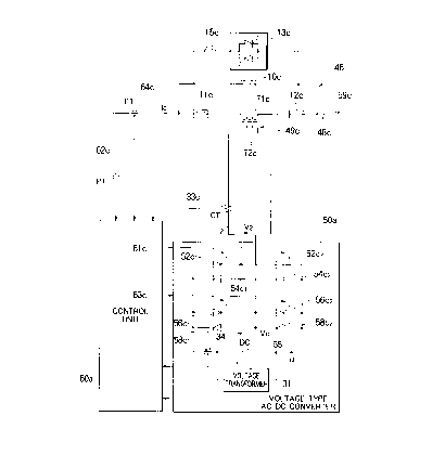
FIG. 15 shows the AC-DC converter protective apparatus
disclosed in U.S. Pat. No. 5,309,346 issued May 3, 1994,
entitled "TRANSMISSION LINE FAULT CURRENT DYNAMIC INVERTER
CONTROL," wherein a voltage-type AC-DC converter connected
in series with a power transmission line is protected from
a transmission line fault current. FIG. 15 shows c-phase,
one of the three phases of an electric power system and a
portion that is common to three phases (without the
subscript c).
In a series system interconnection assembly 46 that is
made up of a voltage-type AC-DC converter protective
apparatus and a power system, the primary winding 71c side
of a series transformer 49c is connected in series with the
c phase of a power system (bus) 48c, and a voltage-type AC-
1 -
.. -
2118862
_ 2 -
DC converter 50 is connected to the secondary winding 72c
side. Also connected to the power system 48c are a current
transformer (CT) 64 for picking up a system current is and
a potential transformer (PT) 62c for picking up a power
system voltage. A line inductance XL 59c that contributes
to a voltage drop VL lies in the power system 48c.
The voltage-type AC-DC converter 50 is constructed
of flywheel diodes 54c1, 54c2, 58c1, and 58c2 which are
respectively anti-parallel connected with self-arc-
extinguishing type semiconductor devices (hereinafter
referred to as "self-arc-extinguishing type devices"), such
as GTOs, 52c1, 52c2, 56c1, and 56c2 in a bridge
configuration. A DC capacitor 55 (common to all a, b, and
c phases) is connected to the DC output side of the
voltage-type AC-DC converter 50, and a voltage transformer
31 for picking up a DC current is connected across the DC
capacitor 55.
The pickup outputs of the current transformer (CT)
64c, the potentia transformer (PT) 62c and the voltage
transformer 31 are fed to a control unit 60 for providing
gate signals for ON/OFF operations of the self-arc-
2178862
- 3 -
extinguishing type devices 52c1, 52c2, 56c1 and 56c2. In
response to these pickup outputs, the control unit 60
provides a gate signal 61c to the self-arc-extinguishing
type devices 52c1 and 52c2, and a gate signal 63c to the
self-arc-extinguishing type devices 56c1 and 56c2.
The operation of the prior art apparatus is now
discussed. Unless otherwise required, the discussion is
given to one phase (c phase) only.
With the purpose of compensating for the voltage
drop VL attributed to the line inductance XL 59c lying in
the c phase of the power system 48, the series system
interconnection assembly 46 is constructed by connecting
the primary winding 71c of the series transformer 49c in
series with the power system 48c so that a voltage V2
generated by the voltage-type AC-DC converter 50 is applied
to the secondary winding 72c.
The control unit 60 picks up system currents i
(which collectively represents system currents ia, ib, and
is for three phases) by the current transformer 64
(inclusive of 64c for the c phase as well), picks up power
system voltages by the voltage transformer 62 (inclusive of
21788b2
- 4 -
62c for the c phase as well), and computes an output
current for compensating for the line voltage and phase.
In accordance with the result of computation, the
control unit 60 outputs the switching signal 61c to the
self-arc-extinguishing type devices 52c1 and 52c2 and the
switching signal 63c to the self-arc-extinguishing type
devices 56c1 and 56c2, thereby controlling the voltage-type
AC-DC converter 50 and compensating for the line voltage
and phase in the c phase.
The DC voltage output of the voltage transformer 31
is fed to the control unit 60. The control unit 60 detects
a fault that takes place in the power system 48c by
monitoring a rise or fall of the DC voltage Vd applied
across the DC capacitor 55 above or below a predetermined
value. When a fault occurrence is detected, the control
unit 60 arc-controls the self-arc-extinguishing type
devices 52c1, 52c2, 56c1 and 56c2 to protect them.
In the prior art voltage-type AC-DC converter
protective apparatus thus constructed, when an excess
system current (hereinafter referred to as "fault current")
generated in the power system due to a system fault in the
21788b2
- 5 -
power system flows through the primary winding of the
series transformer, a fault current proportional to the
ratio of winding is induced in the secondary winding. This
fault current flows through the semiconductor devices of
the voltage-type AC-DC converter (such as the self-arc-
extinguishing type devices and flywheel diodes).
In this case, let KTR represent the winding ratio
of the primary winding to the secondary winding in the
series transformer, Io the maximum value of the current
(power flow) normally flowing through the power system, and
Im the maximum value of the fault current, and a current of
KTR x Im x ~2 flows. Thus, the current rating of
semiconductor devices should be designed to be KTR x Im x
~2. Although the rating of the semiconductor device is KTR
x Im x ~2, a current of KTR x Io x ~2 flows through the
semiconductor devices in normal operation, and this is
translated to the use of the semiconductor devices at a
fraction of their capacity equal to a ratio KTR x Io x ~2 /
KTR x Im x ~2=Io/Im (<1).
To prevent the voltage-type AC-DC converter from
being damaged by a fault current flow, the voltage-type AC-
-..
2~ ~8as2
DC converter requires a power capacity rating Im/Io (1>)
times the power capacity rating for normal operation.
Since the capacity of the voltage-type AC-DC converter is
generally proportional to the number of devices in use, the
number of the devices required is increased by Im/Io times.
Associated components and physical members are also
increased in the same proportion, increasing the cost,
installation space, and bulk of the voltage-type AC-DC
converter and subsequently lowering its reliability.
When a fault current flows due to a fault in the power
system, a fault current proportional to the winding ratio
flows through the secondary winding of the series
transformer. This fault current flows through the
semiconductor devices in the voltage-type AC-DC converter,
heating them and, at the worst case, fusing them.
A circuit breaker may be provided at the secondary
winding side of the series transformer to disconnect the
voltage-type AC-DC converter. When such a circuit breaker
E,. s
. 21 78862
is activated to disconnect the series transformer from the
voltage-type AC-DC converter, the secondary winding of the
series transformer is set to be in an open-circuit. If
this happens, the impedance of the primary winding of the
series transformer becomes infinite. This partitions the
power system at both ends of the primary winding of the
series transformer, and the power system and the converter
system continue to be disadvantageously isolated until the
voltage-type AC-DC converter is recovered from the fault.
The present invention has been developed to resolve
the above described problem, and it is an object of the
present invention to provide a power converter protective
apparatus, in which a voltage-type AC-DC converter having
the power capacity rating for normal operation without
giving consideration to an excess fault current flowing in
the event of a system fault is incorporated in a power
system and the voltage-type AC-DC converter is immediately
,,~,''.~ :'
2178862
protected against an excess current by preventing the fault
current in the power system from flowing into the voltage-
type AC-DC converter.
Accordingly, the present invention relates to a power
converter protective apparatus comprising a transformer
having a primary winding connected in series with a power
system and a secondary winding connected to a power
converter; fault detector means for detecting a fault in
the power system and generating a fault signal upon
detecting a fault in the power system; control means for
outputting a bypass control signal when the fault detector
means generates a fault signal; and normally open current
bypass means connected in parallel with the primary winding
and responsive to the bypass control signal so that a fault
current flowing through the primary winding is bypassed by
the current bypass means in response to detection of a
fault in the power system. The current bypass means
comprises a parallel connection of a high-voltage bypass
_ 8 -
2178862
semiconductor circuit breaker and a high-voltage bypass
mechanical circuit breaker. The high-voltage bypass
semiconductor circuit breaker is closed for a fixed time
upon detection of a fault and thereafter opening. The
high-voltage bypass mechanical circuit breaker is closed
upon detection of a fault and remains closed until the
fault is removed.
Another aspect of the present invention relates to a
power converter protective apparatus comprising a
transformer having a primary winding connected in series
with a power system and a secondary winding connected to a
power converter; fault detector means for detecting a fault
in the power system and generating a fault signal upon
detecting a fault in the power system; control means for
outputting a bypass control signal when the fault detector
means generates a fault signal; and normally open current
bypass means connected in parallel with the secondary
winding and responsive to the bypass control signal so that
9 _
<IMG>
<IMG>
<IMG>
<IMG>
<IMG>
<IMG>
<IMG>
<IMG>
z ~ lss6z
- 18 -
semiconductor devices in the voltage-type AC-DC converter
50a to protect them, while at the same time the series
system interconnection assembly 46 including the primary
winding 71c of the series transformer 49c is protected
against the system fault.
In the voltage-type AC-DC converter 50a thus
constructed, one can design its capacity taking into
consideration,only the maximum currents expected to flow in
normal operating conditions through the self-arc-
extinguishing type devices 52c1, 52c2, 56c1, and 56c2 and
flywheel diodes 54c1, 54c2, 58c1, and 58c2, without giving
consideration to the fault current. Therefore, the count
of the semiconductor devices is minimized and the cost for
the apparatus is reduced, and the installation space and
bulk of the apparatus are reduced, and an increased
reliability is achieved.
Besides picking up the fault current in the power
48c via the current transformer 64c, the control unit 60a
monitors the system voltage through the voltage transformer
62 (collectively represents the voltage transformers for
the three phases including 62c). The control unit 60a may
2'8862
- 19 -
protect the power system by detecting a fault in the power
system, for example, by detecting a voltage drop,
overvoltages, unbalanced threephase voltages, abnormal
frequency, and variations in harmonic contents and by
detecting a fault in the power system.
The control unit 60a detects a fault in the power
system or a fault in the voltage-type AC-DC converter 50a
by monitoring an excess current detected by the current
transformer 33c for picking up an AC current i2 of the
voltage-type AC-DC converter 50a, an excess current
detected by the current transformer 34 for picking up an DC
current id of the voltage-type AC-DC converter 50a, a DC
excess voltage or a DC low voltage detected by the voltage
transformer 31 for picking up a DC voltage Vd of the
voltage-type AC-DC converter 50a. In response to these
detected results, the control unit 60a can immediately
protect the power system 48c or the voltage-type AC-DC
converter 50a.
The reason both the high-voltage bypass
semiconductor circuit breaker 13c and the high-voltage
bypass mechanical circuit breaker lOc are used together is
2178862
- 20 -
as follows. The high-voltage bypass semiconductor circuit
breaker 13c is a fast-switching device that can be quickly
set to ON and if duration of current conduction for a fault
current is set to be short, the rated power and rated
thermal capacity requirements of the semiconductor
components are lowered. If the fault current is left
conducted for a relatively long period of time,
semiconductor,devices such as thyristors or GTOs may be
heated because of their own small resistance, causing
themselves to be damaged.
Thermal considerations thus require heavy-duty
semiconductor devices and cooling equipment, pushing up the
cost for the apparatus and making the apparatus itself
bulky. For this reason, bypassing action of the fault
current that is the cause of heat is thus taken over by the
high-voltage bypass mechanical circuit breaker lOc that is
thermally heavy-duty, in succession to the high-voltage
bypass semiconductor circuit breaker 13c. This arrangement
eliminates the need for a bulky and expensive apparatus
constructed of heavy-duty semiconductor devices and cooling
equipment.
218862
- 21 -
While the high-voltage bypass mechanical circuit
breaker lOc is activated, the series mechanical circuit
breakers llc, 12c connected in series with the primary
winding 71c of the series transformer 49c at its both ends
are left closed. Once they are opened, some time is
required before the series mechanical circuit breakers llc,
12c come back to their closed state, and thus an immediate
interconnection of the series system interconnection
assembly 46 back into the system is difficult at the moment
the system is recovered from the system fault. The series
mechanical circuit breakers llc and 12c are provided to
disconnect the series system interconnection assembly 46
from the power system 48c when the series system
interconnection assembly 46 itself is suspended or fails.
Even when the voltage-type AC-DC converter 50a is
disconnected from the secondary winding 72c for
maintenance, the impedance at the primary winding 71c side
of the series transformer 49c is prevented from getting to
infinity
as long as the series mechanical circuit breakers llc and
12c and the high-voltage bypass mechanical circuit breaker
2178862
lOc are left at an ON state. This arrangement precludes
such an inconvenience that the power system is disconnected
at both terminal ends of the primary winding 71c of the
series transformer 49c and that both the power system 48c
and the converter system remain disconnected from each
other until the voltage-type AC-DC converter 50 is
recovered.
After verifying that the power system 48c has
recovered from the system fault, the control unit 60a opens
the high-voltage bypass mechanical circuit breaker lOc to
cause the voltage-type AC-DC converter 50a to operate
normally. When the power system 48c has recovered prior to
the activation of the high-voltage bypass mechanical
circuit breaker lOc, the control unit 60a, without
activating the high-voltage bypass mechanical circuit
breaker lOc, deactivates the high-voltage bypass
semiconductor circuit breaker 13c for normal operating
conditions (system restart), thereby restarting the
operation of the series system interconnection assembly 46.
Since this restart method allows the series
transformer 49c to be interconnected back into the system
- 22 -
2~ ~sss2
without partially magnetizing the series transformer 49c
and thus without disturbing the power system, the restart
method is applied not only for a system fault recovery but
also for a normal operation routine when the series system
interconnection assembly 46 is initiated.
While the high-voltage bypass semiconductor circuit
breaker 13c is at its OFF state, both terminals are not
electrically insulated to each other. To electrically
isolate the system at both terminals of the high-voltage
bypass mechanical circuit breaker lOc, while it is opened,
the mechanical disconnecting switch 15c connected in series
with the high-voltage bypass semiconductor circuit breaker
13c is set to OFF.
Embodiment 2
In the first exemplary embodiment, the control unit
60a first activates the high-voltage bypass semiconductor
circuit breaker 13c immediately after a system fault is
detected. When the system inductance XL 59c lying in the c
phase of the power system 48c is high, or when the
switching speed to ON in the high-voltage bypass mechanical
circuit breaker lOc is set to be fast, however, the high-
voltage bypass mechanical circuit breaker lOc is fast
- 23 -
2178862
enough in shifting to the ON state to bypass the fault
current without the need for using the high-voltage bypass
semiconductor circuit breaker 13c, because the system
current is at the system fault in the power system 48c
rises at a relatively slow speed as shown in FIG. 4.
FIG. 3 shows schematic diagram of the power converter
protective apparatus according to the second exemplary
embodiment of the present invention. In FIG. 3, the
components equivalent to those with reference to FIG. 1 are
designated with the same reference numerals. The
difference in the circuit from the apparatus of the first
exemplary embodiment is that the high-voltage bypass
semiconductor circuit breaker 13c and the mechanical
circuit breaker 15c, connected in parallel with the high-
voltage bypass mechanical circuit breaker lOc, are no
longer required.
The high-voltage bypass mechanical circuit breaker lOc
is relatively higher at voltage level than a low-voltage
bypass mechanical circuit breaker 21c, as will be described
later, provided at the secondary winding side of the series
transformer 49c, and currents flowing through the contacts
.,
- 24 -
'' 21788fi2
of the high-voltage bypass mechanical circuit breaker lOc
are relatively smaller thus, the contacts of a smaller
contact space and smaller cross-section work. The contacts
are thus light weight, permitting fast open-close
operation. Furthermore, elimination of the high-voltage
bypass semiconductor circuit breaker 13c and the mechanical
circuit breaker 15c reduces the cost and required
installation space of the apparatus.
Embodiment 3
In the first and second exemplary embodiments, the
system current is that flows through the primary winding of
the series transformer 49c at a fault is bypassed by the
high-voltage bypass semiconductor circuit breaker 13c and
the high-voltage bypass mechanical circuit breaker lOc. In
the third exemplary embodiment, as shown in FIG. 5, the
high-voltage bypass mechanical circuit breaker lOc is
connected in parallel with the primary winding 71c of the
series transformer 49c as in the secondary exemplary
embodiment, and further both the low-voltage bypass
mechanical circuit breaker 21c and the low-voltage bypass
semiconductor circuit breaker 20c constructed of
semiconductor devices such as thyristors and GTOs are
- 25 -
21 78 862
connected in parallel with the secondary winding 72c of the
series transformer 49c.
Further provided are a current transformer 32c for
picking up the AC current flowing through the secondary
winding 72c of the series transformer and a current
transformer 33c for picking up the AC current i2 output by
the voltage-type AC-DC converter 50.
Referring now to the timing diagram in FIG. 6, the
operation of the third exemplary embodiment is discussed.
Unless otherwise required, the discussion that follows
is for one phase (c phase) only.
When an excess fault current flows through the primary
winding 71c of the series transformer 49c in the event of a
fault in the power system 48c, a fault current proportional
to the winding ratio of the series transformer 49c flows
through the secondary winding 72c of the series
transformer.
Besides the fault detection method of a system fault
described in the first exemplary embodiment, the control
unit 60b detects a fault by monitoring the current detected
by the current transformer 32c connected in series with the
- 26 -
2178862
secondary winding 72c of the series transformer 49c.
When the system fault is detected, the control unit
60b immediately outputs a gate signal to the low-voltage
bypass semiconductor circuit breaker 20c connected in
parallel with the secondary winding 72c of the series
transformer 49c, to set the low-voltage bypass
semiconductor circuit breaker 20c to ON and then the low-
voltage bypass mechanical circuit breaker 21c to ON but
with a delay time that is inherently unavoidable in its
operation.
The reason both the low-voltage bypass semiconductor
circuit breaker 20c and the low-voltage bypass mechanical
circuit breaker 21c are used together is as follows. The
low-voltage bypass semiconductor circuit breaker 20c is a
fast-switching device that can be quickly set to ON and if
the duration of current conduction for a fault current is
short, the rating of the apparatus is lowered. If the fault
current is conducted for a relatively long period of time,
semiconductor devices such as thyristors or GTOs that
comprise the low-voltage bypass semiconductor circuit
- 27 -
21 78 862
breaker 20c may be heated because of their own small
resistance, possibly causing themselves to be damaged.
Thermal considerations thus require heavy-duty
semiconductor devices and cooling equipment. Such a
problem will be solved if the low-voltage bypass mechanical
circuit breaker 21c having a higher current and thermal
capacity is used to bypass the fault current.
In this case, the series mechanical circuit breakers
llc, 12c connected in series with the primary winding 71c
of the series transformer 49c at both its ends are left
closed. Once they are opened, some time is subsequently
required before the series mechanical circuit breakers llc,
12c come back to their closed state, and thus an immediate
interconnection of the series system interconnection
assembly 46 back into the system is difficult at the moment
the system has recovered from the system fault.
The series mechanical circuit breakers llc and 12c are
opened when the series system interconnection assembly 46
itself is suspended or fails. By activating the high-
voltage bypass mechanical circuit breaker lOc, the series
,,
- 28 -
2~ ~aas2
d..;
system interconnection assembly 46 is disconnected from the
power system 48c.
After verifying that the power system 48c has
recovered from the system fault, the control unit 60b opens
the low-voltage bypass mechanical circuit breaker 21c to
cause the voltage-type AC-DC converter 50a to operate
normally. When the fault is removed prior to the
activation of the low-voltage bypass semiconductor circuit
breaker 20c, the control unit 60b, without activating the
low-voltage bypass mechanical circuit breaker 21c,
deactivates the low-voltage bypass semiconductor circuit
breaker 20c for normal operating conditions (system
restart), thereby restarting the operation of the series
system interconnection assembly 46.
Since the low-voltage bypass semiconductor circuit
breaker 20c handles a relatively higher current and a
relatively lower voltage than the high-voltage bypass
semiconductor circuit breaker 13c, a narrower insulating
separation is permitted. A compact and low-cost apparatus
thus results.
Embodiment 4
In the third exemplary embodiment, the low-voltage
r
- 29 -
.~. 2178862
bypass semiconductor circuit breaker 20c is first set to ON
immediately after a system fault is detected. When the
system inducatance XL 59c lying in the c phase of the power
system 48c is high, or when the switching speed to ON in
the low-voltage bypass mechanical circuit breaker 21c is
set fast, however, the low-voltage bypass mechanical
circuit breaker 21c is fast enough in shifting to the ON
state to bypass the fault current without the need for
using the low-voltage bypass semiconductor circuit breaker
20c, because the system current is at the system fault in
the power system 48c rises at a relatively slow speed as
shown in FIG. 8.
FIG. 7 shows the schematic diagram of the power
converter protective apparatus according to the fourth
exemplary embodiment of the present invention. In FIG. 7,
the components equivalent to those with reference to FIG. 5
are designated with the same reference numerals. The
difference in circuit from the apparatus of the third
exemplary embodiment is that the low-voltage bypass
E
- 30 -
21 78 862
semiconductor circuit breaker 20c, connected in parallel
with the low-voltage bypass mechanical circuit breaker 21c,
is no longer needed.
Upon detecting a system fault, the control unit 60b
immediately activates the low-voltage bypass mechanical
circuit breaker 21c connected in parallel with the
secondary winding 72c of the series transformer 49c to
prevent an excess current due to the fault from flowing
into the voltage-type AC-DC converter 50a. Since in this
case, the rate of rising of the system current is at the
fault in the power system 48c is relatively slow, the
relatively slow response low-voltage bypass mechanical
circuit breaker 21c is shifted sufficiently fast to the ON
state to bypass the fault current.
Elimination of the low-voltage bypass semiconductor
circuit breaker 20c reduces the cost and required
installation space of the apparatus.
Embodiment 5
In the first exemplary embodiment, the high-voltage
bypass mechanical circuit breaker lOc is connected in
parallel with the series connection of the primary winding
71c and the series mechanical circuit breakers llc, 12c,
and furthermore the series connection of the high-voltage
- 31 -
2178862
bypass semiconductor circuit breaker 13c and the mechanical
disconnecting switch 15c is connected in parallel with the
high-voltage bypass mechanical circuit breaker lOc. In
this embodiment, however, the mechanical disconnecting
switch 15c is eliminated and the high-voltage bypass
semiconductor circuit breaker 13c is connected in parallel
with the primary winding 71c as a high-voltage shorting
semiconductor circuit breaker 14c.
Referring to drawings, the fifth exemplary embodiment
is now discussed. FIG. 9 is the schematic diagram of the
power converter protective apparatus according to the fifth
exemplary embodiment of the present invention. In FIG. 9,
the components equivalent to those with reference to FIG. 1
are designated with the same reference numerals. The high-
voltage shorting semiconductor circuit breaker 14c
comprising semiconductor devices such as thyristors or GTOs
is connected in parallel with the primary winding 71c of
the series transformer 49c.
Referring to the timing diagram in FIG. 10, the
operation of the fifth exemplary embodiment is discussed.
Upon detecting a system fault, the control unit 60a sends a
L.,..Y
- 32 -
,~ 2178862
gate signal to the high-voltage shorting semiconductor
circuit breaker 14c to set it to ON, and then sends an ON
signal to the high-voltage bypass mechanical circuit
breaker lOc to set it to ON but with a delay time that is
inherently unavoidable in its operation.
By allowing the fault current to flow through the
high-voltage bypass mechanical circuit breaker lOc, the
series system interconnection assembly 46 including the
primary winding 71 of the series transformer 49c is
protected against the system fault.
In this embodiment, the operation of the high-voltage
shorting semiconductor circuit breaker 14c is substantially
identical to that of the high-voltage bypass semiconductor
circuit breaker 13c described with reference to the first
exemplary embodiment.
By opening the series mechanical circuit breakers llc,
12c, the high-voltage shorting semiconductor circuit
breaker 14c is disconnected from the power system 48c. The
high-voltage shorting semiconductor circuit breaker 14c can
thus undergo maintenance service without interrupting power
transmission if the high-voltage bypass mechanical circuit
breaker lOc is let ON.
z ,.
- 33 -
21 78 862
Embodiment 6
In the first exemplary embodiment, the high-voltage
bypass mechanical circuit breaker lOc is connected in
parallel with the series connection of the primary winding
71c and the series mechanical circuit breakers llc, 12c,
and furthermore the series connection of the high-voltage
bypass semiconductor circuit breaker 13c and the mechanical
circuit breaker 15c is connected in parallel with the high-
voltage bypass mechanical circuit breaker lOc. In this
embodiment, only the series connection of the mechanical
circuit breaker 15c and the high-voltage bypass
semiconductor circuit breaker 13c is connected in parallel
with the primary winding 71c.
Referring to drawings, the sixth exemplary embodiment
is now discussed. FIG. 11 is the schematic diagram of the
power converter protective apparatus according to the sixth
exemplary embodiment of the present invention. In FIG. 11,
the components equivalent to those with reference to FIG. 1
are designated with the same reference numerals. The sixth
exemplary embodiment differs from the first exemplary
embodiment in that the high-voltage bypass mechanical
,,
y
- 34 -
. 2178862
circuit breaker lOc is dispensed with, and the rest of the
construction is identical to that of the first exemplary
embodiment.
The operation of the sixth exemplary embodiment is
discussed referring to the timing diagram in FIG. 12. The
sixth exemplary embodiment is identical to the first
exemplary embodiment in operation in that upon detecting a
system fault, the control unit 60a immediately activates
the high-voltage bypass semiconductor circuit breaker 13c,
but is different in that the system current is is prevented
from flowing into the series system interconnection
assembly 46 by keeping the high-voltage bypass
semiconductor circuit breaker 13c activated until the
system is recovered from its fault.
In the high-voltage bypass semiconductor circuit
breaker 13c, semiconductor switching devices should be
rated so that they allow fault currents to be continuously
conducted therethrough during the system fault or
maintenance time of the series system interconnection
assembly 46. However, since the high-voltage bypass
mechanical circuit breaker lOc is dispensed with, a compact
and low-cost apparatus results with less of an installation
space requirement.
~'°~~.
- 35 -
2178882
Embodiment 7
In the third exemplary embodiment, both the low-
voltage bypass mechanical circuit breaker 21c and the low-
voltage bypass semiconductor circuit breaker 20c are
connected in parallel with the secondary winding 72c. In
this embodiment, the low-voltage bypass mechanical circuit
breaker 21c only is connected in parallel with the
secondary winding 72c.
Referring to drawings, the seventh exemplary
embodiment is discussed. FIG. 13 is the schematic diagram
of the power converter protective apparatus according to
the seventh exemplary embodiment of the present invention.
In FIG. 13, the components equivalent to those with
reference to FIG. 5 are designated with the same reference
numerals. The seventh exemplary embodiment differs from
the third exemplary embodiment in that the low-voltage
bypass mechanical circuit breaker 21c is dispensed with,
and the rest of the construction is identical to that of
the third exemplary embodiment.
The operation of the seventh exemplary embodiment is
discussed referring to the timing diagram in FIG. 14. The
seventh exemplary embodiment is identical to the third
exemplary embodiment in operation in that upon detecting a
'.,;
- 36 -
- ~... 2178862
system fault, the control unit 60b immediately activates
the low-voltage bypass semiconductor circuit breaker 20c,
but is different in that, to prevent a fault current from
flowing into the voltage-type AC-DC converter 50a upon the
detection of the system fault, the low-voltage bypass
semiconductor circuit breaker 20c is immediately set to ON,
and then the low-voltage bypass semiconductor circuit
breaker 20c is activated with a delay time that is
inherently unavoidable in its operation.
The third exemplary embodiment uses both the high-
voltage bypass mechanical circuit breaker lOc and the low-
voltage bypass semiconductor circuit breaker 20c, while the
seventh exemplary embodiment dispenses with the low-voltage
bypass semiconductor circuit breaker 20c. Therefore, a
compact and low-cost apparatus results.
,,.
- 37 -