Language selection

Search

Patent 2179299 Summary

Third-party information liability

Some of the information on this Web page has been provided by external sources. The Government of Canada is not responsible for the accuracy, reliability or currency of the information supplied by external sources. Users wishing to rely upon this information should consult directly with the source of the information. Content provided by external sources is not subject to official languages, privacy and accessibility requirements.

Claims and Abstract availability

Any discrepancies in the text and image of the Claims and Abstract are due to differing posting times. Text of the Claims and Abstract are posted:

  • At the time the application is open to public inspection;
  • At the time of issue of the patent (grant).
(12) Patent: (11) CA 2179299
(54) English Title: FIXING CLAMP
(54) French Title: BRIDE DE FIXATION
Status: Term Expired - Post Grant Beyond Limit
Bibliographic Data
(51) International Patent Classification (IPC):
  • F16L 03/24 (2006.01)
  • F16B 02/14 (2006.01)
  • F16L 03/00 (2006.01)
(72) Inventors :
  • SKJAEVELAND, MAGNE (Norway)
(73) Owners :
  • KVERNELAND KLEPP A/S
(71) Applicants :
  • KVERNELAND KLEPP A/S (Norway)
(74) Agent: SMART & BIGGAR LP
(74) Associate agent:
(45) Issued: 1999-02-23
(86) PCT Filing Date: 1994-12-16
(87) Open to Public Inspection: 1995-06-29
Examination requested: 1996-06-17
Availability of licence: N/A
Dedicated to the Public: N/A
(25) Language of filing: English

Patent Cooperation Treaty (PCT): Yes
(86) PCT Filing Number: PCT/NO1994/000207
(87) International Publication Number: NO1994000207
(85) National Entry: 1996-06-17

(30) Application Priority Data:
Application No. Country/Territory Date
P 43 43 676.5 (Germany) 1993-12-21

Abstracts

English Abstract


A clamp having an U-shaped clamp
body (1) which engages a profile such as
a rectangular or square pipe (2) on three
sides (3, 4, 5), while the fourth side (6) of
the profile is engaged by a bolt (7) which
is secured by a nut (8) and extends through
conical holes (9, 10) in the free legs of
the clamp body (1). Conical washers (11,
12) on the bolt (7) engage the conical
holes (9, 10) on the far side from the pipe
(2), meaning that the bolt (7) is located
somewhat eccentrically in the holes (9,
10). Tightening the bolt (7) by means
of the nut (8) makes the clamp body (1)
squeeze the top side (3) and bottom side
(4) of the pipe (2). The conical washers
(11, 12) in the conical holes (9, 10) make
the bolt (7) squeeze the pipe (2) in the
direction of the back side (5) of the pipe.
The pipe (2) is thus squeezed from all
sides, giving a strong and stable clamp
connection.


French Abstract

L'invention concerne une bride de fixation ayant un corps (1) en forme de U qui se monte sur un tuyau (2) de section rectangulaire ou carrée, sur trois côtés (3, 4, 5) dudit tuyau, une vis (7) bloquée par des écrous (8) étant montée sur le quatrième côté (6). Ladite vis (7) passe par des trous coniques (9, 10) ménagés dans les branches libres du corps (1) de la bride. Les rondelles coniques (11, 12) de la vis (7) sont logées dans les trous coniques (9, 10), du côté éloigné du tuyau (2), la vis (7) étant ainsi située légèrement excentriquement dans les trous (9, 10). Le blocage de la vis (7) au moyen de l'écrou (8) fait que le corps (1) de la bride serre le côté supérieur (3) et le côté inférieur (4) du tuyau (2). Grâce à la présence des rondelles coniques (11, 12) dans les trous coniques (9, 10), la vis (7) serre le tuyau (2) en direction de son côté arrière (5). Le tuyau (2) est ainsi serré sur tous ses côtés, et l'on obtient ainsi une fixation solide et stable de la bride.

Claims

Note: Claims are shown in the official language in which they were submitted.

THE EMBODIMENTS OF THE INVENTION IN WHICH AN EXCLUSIVE
PROPERTY OR PRIVILEGE IS CLAIMED ARE DEFINED AS FOLLOWS:
1. A clamp for securely attaching objects to a profile
member, comprising a substantially U-shaped clamp body having
a web connecting two approximately parallel legs; a hole
extending through a free end of each leg, the holes being
coaxially aligned; a cylindrical screw bolt extending through
the aligned holes and being provided with at least one movable
tightening nut; and each end portion of the cylindrical screw
bolt including an inclined face co-acting with a complementary
inclined face at least partially defining each of the holes,
said co-acting faces, upon tightening of said movable nut
interacting to urge the cylindrical screw bolt laterally
toward the profile member, said legs, web and cylindrical
screw bolt being adapted to circumscribe the entirety of the
profile member, such that the tightening of said movable nut
simultaneously clamps the legs of the profile member and moves
the cylindrical screw bolt laterally toward the profile
member.
2. A clamp as set forth in claim 1, wherein the
cylindrical screw bolt, adjacent each of the opposite end
portions thereof, is provided with a conical washer tapering
in a direction toward the other washer, each conical washer
cooperating with a complementarily conical wall defining each
of said aligned holes.
3. A clamp as set forth in claim 1 or claim 2 for
- 3 -

attaching objects to a profile member that is square or
rectangular, wherein said web of the clamp is at right angles
to the parallel legs thereof.
4. A claim as set forth in claims 1 to 3 wherein said
screw bolt is unthreaded over the length thereof that extends
between said holes.
- 4 -

Description

Note: Descriptions are shown in the official language in which they were submitted.


211 7~ 299
The invention relates to a clamp for attaching
objects to pipes and other profiles.
Clamps are often used for adjustable attachment of
objects to pipes and other profiles. Simple clamp units
normally engage only a part of the pipe or profile, and the
strength of an optimal clamp connection is not achieved. More
enhanced clamps tend to be more complex, often consisting of
two or more parts and a number of bolts and nuts.
The purpose of the invention is to eliminate these
disadvantages and provide a simple and effective clamp,
especially for attaching objects to square and rectangular
pipes or profiles.
The invention accordingly provides a clamp for
securely attaching objects to a profile member, comprising a
substantially U-shaped clamp body having a web connecting two
approximately parallel legs; a hole extending through a free
end of each leg, the holes being coaxially aligned; a cylin-
drical screw bolt extending through the aligned holes and
being provided with at least one movable tightening nut; and
each end portion of the cylindrical screw bolt including an
inclined face co-acting with a complementary inclined face at
least partially defining each of the holes, said co-acting
faces, upon tightening of said movable nut interacting to urge
the cylindrical screw bolt laterally toward the profile
member, said legs, web and cylindrical screw bolt being
adapted to circumscribe the entirety of the profile member,
such that the tightening of said movable nut simultaneously
clamps the legs of the profile member and moves the
cylindrical screw bolt laterally toward the profile member.
-- 1 --
~ 73577-8

a~1 7~ 299
The provision of conical washers round opposite
sides of the bolt prove particularly advantageous.
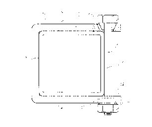
An embodiment of the invention will be described in
the following example with reference to the accompanying
drawing.
A clamp body 1 engages a square pipe 2 on three
sides, top side 3, bottom side 4 and back side 5, while the
front side 6 is engaged by a bolt 7 which is secured by a nut
8 and extends through conical holes 9, 10 in the top and
bottom parts of the clamp body 1 and through conical washers
11, 12. The holes
9, 10 have a common centre line which is parallel to the front
side 6. The distance between said centre line and the front
side 6 is less than the bolt 7 radius, while the minimum
diameter of holes 9, 10 exceeds the diameter of the bolt 7,
which makes it possible to install the bolt 7. The conical
washers 11, 12 on the bolt 7 engage the conical holes 9, 10 on
the far side from the pipe 2, meaning that the bolt 7 is
located eccentrically in the holes 9, 10. Tightening the bolt
7 makes the clamp body 1 squeeze the top side 3 and bottom
side 4 of the pipe 2. The conical washers 11, 12 in the
conical holes 9, 10 force the bolt 7 in the direction of the
back side 5 of the pipe 2. Thus the pipe 2 is squeezed from
all sides, giving a strong and stable clamp connection.
The clamp body 1 may have support members for
objects to be attached to the pipe 2, and it may have any
number of bolts.
- 2 -
73577-8

Representative Drawing
A single figure which represents the drawing illustrating the invention.
Administrative Status

2024-08-01:As part of the Next Generation Patents (NGP) transition, the Canadian Patents Database (CPD) now contains a more detailed Event History, which replicates the Event Log of our new back-office solution.

Please note that "Inactive:" events refers to events no longer in use in our new back-office solution.

For a clearer understanding of the status of the application/patent presented on this page, the site Disclaimer , as well as the definitions for Patent , Event History , Maintenance Fee  and Payment History  should be consulted.

Event History

Description Date
Inactive: Expired (new Act pat) 2014-12-16
Inactive: IPC from MCD 2006-03-12
Grant by Issuance 1999-02-23
Inactive: Final fee received 1998-11-09
Pre-grant 1998-11-09
Notice of Allowance is Issued 1998-10-01
Letter Sent 1998-10-01
Inactive: Status info is complete as of Log entry date 1998-09-28
Inactive: Application prosecuted on TS as of Log entry date 1998-09-28
Inactive: Approved for allowance (AFA) 1998-08-28
All Requirements for Examination Determined Compliant 1996-06-17
Request for Examination Requirements Determined Compliant 1996-06-17
Application Published (Open to Public Inspection) 1995-06-29

Abandonment History

There is no abandonment history.

Maintenance Fee

The last payment was received on 1998-10-27

Note : If the full payment has not been received on or before the date indicated, a further fee may be required which may be one of the following

  • the reinstatement fee;
  • the late payment fee; or
  • additional fee to reverse deemed expiry.

Patent fees are adjusted on the 1st of January every year. The amounts above are the current amounts if received by December 31 of the current year.
Please refer to the CIPO Patent Fees web page to see all current fee amounts.

Owners on Record

Note: Records showing the ownership history in alphabetical order.

Current Owners on Record
KVERNELAND KLEPP A/S
Past Owners on Record
MAGNE SKJAEVELAND
Past Owners that do not appear in the "Owners on Record" listing will appear in other documentation within the application.
Documents

To view selected files, please enter reCAPTCHA code :


To view images, click a link in the Document Description column. To download the documents, select one or more checkboxes in the first column and then click the "Download Selected in PDF format (Zip Archive)" or the "Download Selected as Single PDF" button.

List of published and non-published patent-specific documents on the CPD .

If you have any difficulty accessing content, you can call the Client Service Centre at 1-866-997-1936 or send them an e-mail at CIPO Client Service Centre.


Document
Description 
Date
(yyyy-mm-dd) 
Number of pages   Size of Image (KB) 
Description 1998-08-04 2 78
Claims 1998-08-04 2 48
Abstract 1995-06-28 1 51
Description 1995-06-28 1 14
Drawings 1995-06-28 1 10
Description 1995-06-28 2 53
Representative drawing 1999-01-07 1 4
Representative drawing 1997-06-22 1 7
Commissioner's Notice - Application Found Allowable 1998-09-30 1 163
Correspondence 1998-11-08 1 40
Fees 1996-07-11 1 46
PCT 1996-06-16 7 320