Note: Descriptions are shown in the official language in which they were submitted.
2 ~ 79~
.
Method for and li'r , ' '- ) of an Optical Fiber
Field of the Invention
This invention relates to an optical system and method for epoxyless coupling of a
pre-formed ferrule to an optical fiber. More particularly, an aspect of the invention relates
to hermetically enveloping at least a portion of an optical fiber with a pre-formed ferrule
of a similar and/or compatible material.
Ba.4. ~ . ~ of the Invention
Optical fibers are used in a wide variety of applications ranging from
tPI~."" " ", 1, I;ca~h)ll~ to medical technology and optical ~ JUII~ . Because of their
unique structure, optical fibers are capable of highly accurate transmission of light, which
is relatively unaffected by i~ rc~cll~,c, diffusion, and other signal de-enhancing
rhPnr nnPn~ Ho~vever, for optical fibers to function at their optimum potential they must
be structurally intact and free of scratches, cracks, or leaks.
Optical fibers consist of a core material that is surrounded by a cladding. The
difference between the indexes of refraction of the core and cladding materials (which, in
some cases, are simply different types of fused silica glass) allows the optical fiber to
function. Most commercially available optical fibers, in addition, have an external "buffer
or jacket". The jacket is a thin coating (usually a plastic, other polymer, or metal) which
is applied to the fiber to protect it from being scratched during handling ând to limit the
amount of water than can come into contact with the fiber. Scratching or contact with
water or moisture can deleteriously affect both the optical properties and the strength of
I
21 7q~
the glass fiber. In addition to shielding the fiber's surface, the buffer also operates to help
maintain the high tensile strength and the bending capability of the glass optical fibers.
A number of fiber optic d~ liulls require that one terminus of the fiber be
s located in an ~IIVil~JlUll~llL isolated from the other terminus. Tbis implies the use of a
connector, coupling device, or "feedthrough" which serves as the point of
, ."""",.,i..,.lion between the distinct environments. Oftentimes, it is necessary or
desirable for the point of ~ iorl between the ellVilUlllll~ i to be completely
sealed except for the presence of the optical fiber. Herein arises the need for a satisfactory
0 method to hermetically seal optical fibers within metal fittings.
Fabrication of hermetic fiber optic-to-metal C~ has until recently been
difficult due to a number of factors. Principal among these is the large thermal expansion
mismatch between the very low coefficient of expansion of the optical fibers (most
commonly made of fused silica glass) and the high coefficient of expansion of the metal
shell to which the optical fibers are attached. This difference can cause severe stressing of
the fiber optic ~,ullllJu~l~.lb, especially where fabrication methods use application of heat,
which, in turn, can cause ull~ ilable cracks and leaks in the optical fibers.
A United States patent 5,143,531 in the name of Kramer issued September I,
1992 and assigned to the United States of America as represented by the United States
Depa~tment of Energy, discloses a glass-to-glass hermetic sealing technique which can be
used to splice lengths of glass fibers together. A solid glass pre-form is inserted into the
cavity of a metal component which is then heated to melt the glass. An end of an optical
fiber is then advanced into the molten glass and the entire structure is cooled to solidify
the glass in sealing ~"~".,J~",. ,I with the optical fiber end and the metal cavity.
2 1 79456
Another U.S. patent 5,337,387 in the name of the same inventor issued August 9,
1994 and relates to a method of the continuous processing of hermetic flber optic
~,U~ and the resultant fiber optic-to-metal C~ Ullci~ by assembling and
fixturing elements comprising a metal shell, a glass pre-form and a metal-coated fiber
5 optic into desired relative positions and then sealing said fixtured elements, preferably
using a continuous heating process.
Although Kramer's inventions for hermetically sealing optical fibers may performtheir intended functions, the general approach is believed to be a relatively costly and
10 somewhat complex.
Methods are known for placing and affixing optical fibers in ferrules and sleeves
of different types for the purposes of providing a protective sheath for reducing damage
to optical fibers that would otherwise be exposed, and for attempting to provide a housing
15 for optical fibers. Furthermore, such ferrules or sleeves have been used as housings in
which optical fibers are fused together. In many of these applications an a&esive such as
epoxy is placed in the ferrule with the optical fiber to provide a bonded seal between the
fiber and the ferrule.
In one U.S. patent 5,094,518 issued March l 0 1992 in the name of Musk a
method of making an opto-electronic component comprises inserting a pre-assembled
device carrier into a mould, filling the mould with a light and/or thermally curable
material.
In yet another U.S. patent 5,061,034 in the name of Fujikawa et al issued October
29, 1991, a permanent connector for optical fibers comprises a protective glass tube, a
capillary tube received therein and er~ntrirAlly joined thereto; the two tubes are made of
ultraviolet-~ glass; an a&esive-passing groove is formed in the middle
2~ 7~56
portion of the capillary tube and opening on the side opposite to the side where they are
joined together. An ultraviolet-curing type adhesive agent is cllarged into the permanent
connector for optical fibers and the ends of the fibers are inserted thereinto. Fujikawa's
device and Musl;'s device are both relativel~ complex and do not appear to be optimal
5 solutions for hermetically sealing an optical fiber.
Therefore, it is an object of this invention to provide a method of ~nr~rs~ ti n~ an
optical flber that is practicable for hermetic optical fiber applications.
It is a further object ofthe in~ention to provide an i~l~A~ ;ve and reliable optical
fiber [~dllu~ugl~ for hermetic optical fiber applications.
It is yet a further object of the invention to provide an epoxyless method of
reinforcing an optical fiber by fusing it to a stiffening sleeve in tlle presence of heat.
Summary of the Invention
In accordance with the invention, a method of ~ r~ t~ at least a portion of
an optical fiber is provided comprising the steps of: providing a ferrule having a bore, the
20 ferrule at least about and deflning the bore comprising a material that is similar to and
fusible with an optical fiber sized to tightly flt into the bore; inserting at least a portion of
the optical fiber into the bore; heating the ferrule sufficiently to fuse at least a portion of
the optical fiber inserted into the bore with the ferrule;
In accordance ~vith the invention there is further provided, a method of
rnr~rs~ ting at least a portion of an optical fiber comprising the steps of placing an
optical fib~r into a tube having an inner wall made of a material that will fuse to the fiber
2 ~ 7~ 5~
.
in th~ presence of suitable heat; and, vitrifying and collapsing said tube onto the fiber to
encapsulate a portion of optical fiber within the tube.
In accordance with another aspect of the invention there is provided an optical
5 fiber having an outer cladding sllhst~nti:~lly consisting of silica, the cladding on at least a
portion of the optical fiber being r~ I by and fused with a sleeve having an inner
wall defining a bore into which the fiber is disposed, sllhst~nt~ y consisting of silica.
Ad~ ly this invention provides a method of thickening a section of
lo optical fiber by collapsing and fusing a tube of compatible material onto it. The thickened
section comprising the at least fused fiber and tube can then be soldered thereby
providing a hermetically sealed feedthrough. In particular, this method has been shown to
exhibit significantly less stress damage and crack formation than hermetic fiber optic
~U~ made using other techniques
Brief Description of the Drawings
Exemplary embodiments of the invention will now be described in conjunction
with th~ drawings, in which:
Fig. I is a cross sectional view of an optical fiber placed into an opening a fenule
prior to the application of heat ror collapsing the ferrule;
Fig. Ia is a is a cross sectional view of an optical fiber placed into an opening a
25 ferrule having a stepped down opening for allowing a jacketed fibre to be inserted part
way into the rerrule prior to the application of heat for collapsing the ferrule;
~ ~ 7~
Fig. 2 is a cross sectional view of the optical fiber ferrule ~ 11 Ig~ shown in
Fig.l after the application of heat whereby the ferrule is shown collapsed onto the optical
fiber;
Fig. 3 is a cross sectional view of the optical fiber "" ,., I~ shown in Fig. 2,5 wherein the mode field diameter within the core of the optical fiber within the ferrule is
thermally expanded;
Fig. 4a is a cross sectional view of an alternative embodiment of a sleeve having
flared ends for use in accordance with the invention;
Fig. 4b is a pictorial view of a sleeve having a rectangular bore for
accommodating a pair of optical fibers;
Fig. 4c is an end view of the sleeve shown in Fig. 4b;
Fig. 4d is an end view of a sleeve having a bore with a triangular cross section;
Fig. 5a is an end view of the sleeve shown in Fig. I, collapsed on an optical fiber
as is shown in Fig 2;
~o
Fig. ~b is an end view of an optical fiber glued into a sleeve in a conventionalmarLner; and,
Fig. 6 is a side view of a sleeve shown with two optical fibers placed within prior
25 to collapsing the sleeve on the optical fib~rs.
Detailed Description
21 ;79~56
.
The terms "sleeve, felrule, and tube" shall be used illlt~ dbly in this
description to represent a housing having a bore at least partially defined therethrough.
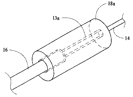
Referring now to Fig. 1, a conventional optical fiber 10 is shown having a portion
of its lengtn inserted into a flber tube or sleeve 18 consisting 51~hct~nfi~1ly of silica. Tbe
sleeve 18 can be a precision sleeve having a wall 13 deflning an inner diameter as small
as 125.1 ~Lm to ,~ t. an optical fiber having an outer diameter of 125 llm or the
inner diameter of the sleeve can be larger than 126 ,um. The outer diameter of the sleeve
is not conflned to, but may be in the range of I mm. The optical flber 10 has a core 12,
lo and a cladding 14 that both consist substantially of silica having different refractive
indexes; an outer protective jacket 16 is sho~vn on a portion of the fiber outside the sleeve
18. Typical dimensions of t~1e core 12 for single mode fiber are in the range of 6 to 12
~Lm. The outer diameter of the cladding 14 is generally about 125 llm and the protective
jacket 16 outer diameter typically can ranges from 250 to 900 llm.
In an attempt to obviate known problems in the fabrication of hermetic fiber optic
components related to t~lermal expansion mismatch between the very low coefficient of
expansion of the fused silica glass optical fibers and the differing coefficient of expansion
of the other mate~ials, this invention provides a sleeve of a compatible material (silica)
that is sllh~t~nti:~lly matched in coefficient of expansion to that of optical fiber, thereby
reducing stressing of the optical fiber in the application of heat which otherwise can cause
le~ila~le cracks and leaks in the optical fibers.
Two materials that provide a match to optical fiber are silica ~llhst~nti~lly
consisting of SiO2 (nearly 100%) and Vycor TM (about 95% silica and partially consisting
of Boron Oxide) available from the Corning Glass Co. Sleeves made of either of these
materials will fuse to the cladding 14 that substantially consists of pure silica at
21 7945~
.
UUC~ of about 1800 C. Thus, it is preferred if the sleeve 18 consists of or at
least substantially consists of the same material as the cladding 14.
Referring to Fig. I a a ferrule 1 8a is shown having a stepped down inner wall 1 3a
s for allowing a jac~eted fiber to be inserted part way into the opening. The stripped optical
flber is inserted tllrough the ferrule 1 8a. Heat is provided to one end (not shown) and one
portion of th~ tube is collapsed upon the fiber.
Cu~v~ lly and optionally, the opening at the end of the sleeve 18 is flared to
lo ease th~ entry of a fiber end into the end of the sleeve 18. Referring now to Fig. 4a, a
sleeve 48 is shown having a flared end 47 and having bore extending only part~way
through providing an opening into which a fiber end may be inserted, rather thanproviding a through-hole as shown in Fig. 1. In an alternative embodiment, bores having
a cross-section other than circular can be provided. For example, and referring now to
5 Fig. 4c, a substantially rectangular bore cu~ ltly ~ r~ two optical fibers
for fusion with the bore in the presence of sufficient ~l~at. A triangular bore is shown in
Fig. 4d for ~ o"",,~,.l"li"g 3 optical fibers.
When tlle glass tube 18 is heated to a sufficient ltl~lp~ldlul~ external surfacezo tension on the tube shrinks and collapses the diameter of the tube 18. Fig. 2 illustrates
this process whereby a micro-flame burner 20 heats the silica tube 18 to about 1800 C
until th~ tube 18 collapses and at least partially fuses with the cladding 14. Fig. 5a
illustrates complete fusion of the cladding and the tube inner diameter; the cladding and
the tube are not dirr~l~lllial,le and only the core of the fiber can be di~ ,ui~ d. In
25 contrast to this, Fig. 5b shows a conventional .~ where an optical fiber withadhesive in the form of epoxy is placed into a bore of a sleeve 58. The cross section
shows a ring 57 defining a boundary of epoxy at the interface between the fiber cladding
and the wall of the bore.
21794jS
Referring once more to Fig. 2, advallla~vu~ly by heâting the tube 18 and
~.vl15~ y the fiber 10 inside the tube at such a high temperature, ~he mode field 12a
of the core 12 expands, yielding a hermetically sealed optical fiber end with a thermally
5 expanded core (TEC). Alternatively, the fiber can be placed in the sleeve, heated slowly
(for a few hours) at a temperature of âbOut 1300 C to expand the mode field diameter of
the core, and later can be heated at suhif ~nti~lly higher temperatures to collapse the tube
18 onto the optical fiber cladding 1~. Advantageously, and more importantly in
applications ~vhere tolerances are very small, when the fiber is heated and fused to the
o sleeve, the core of the fiber self-centers within the sleeve. This simplifies later alignment
of the reinforced fused fiber and sleeve.
Optionally, the tube 18 of the resulting r~ optical fiber can be soldered
or dipped in metal bath to coat the outer periphery of the device. Of course other coating
and depositing methods may be envisaged to apply a metal to the outside of the tube 18
for hermetic sealing with a metal package.
In an alternative embodiment of this invention shown in Fig. 6, the silica tube 18
described heretofore, can be used in a similar manner to reinforce and hold optical fibers,
20 hermetically sealing them, however this ~mh-)~1imrnt provides for two optical fibers 10a
and I Ob to be held, reinforced, and fused end-to-end together inside the tube 18. First,
ends of the fibers are placed into the tube 18 such that they are in contact to one another.
Sufficient heat is then applied until the fibers have fused. Optionally, silica glass soot
may be inserted into the tube prior to the placement of either fiber in the tube or after the
placement of a first fiber and prior to the insertion of the second optical fiber. The soot,
having a lower melting point than the optical fiber fuses and solders the adjacent ends of
tlle fibers together inside the tube in the presence of heat applied to the tube 18.
2 1 79456
.
Of course, numerous other ~ may be envisaged, without departing
from the spirit and scope of the invention.