Note: Descriptions are shown in the official language in which they were submitted.
2179475
Description
CONNECTOR SYSTEM FOR MOUNTING
AN EXHAUST PIPE TO A TRUCK CAB
S
Field of the Invent Qtt
The present invention relates to a connector for mounting a vertical
exhaust pipe to a cab of a truck.
Back~exound of the Invention
Truck exhaust pipes are commonly mounted to extend vertically next to
the cab to conform to regulations for hauling certain loads and to enhance the
aesthetics
of the vehicle. Trucks for hauling food products, for example, must expel the
exhaust at
a point that is positioned above the load to prevent the exhaust from
contaminating the
I S food products. Truckers also like to have bright, shiny chrome exhaust
pipes next to the
cab to enhance the appearance of their trucks. Thus, it is generally desirable
to mount
exhaust pipes to extend vertically next to the cab.
When trucks have an air cab suspension, however, several problems arise
in connection with vertically mounted exhaust pipes. A significant amount of
vertical
and Lateral displacement occurs between vertically mounted exhaust pipes and
the cab
because the exhaust pipes are mounted to the frame of the vehicle while the
cab is
mounted to a separate air suspension system. The largest displacement between
an
exhaust pipe and a cab happens when frame "racking" occurs such that one frame
member is displaced with respect to the other. Racking can cause up to 3.0" of
vertical
displacement between the pipes and the cab. A lesser amount of displacement
occurs
when the truck goes over bumps or potholes in the road surface. Accordingly,
the
upper end of vertical exhaust pipes should be secured to the outer wall of the
cab to
prevent damage to the pipes and cab.
Conventional mounting systems do not adequately secure vertical pipes
to the cab. In securing the upper end of a vertical pipe to the cab, lateral
displacement
should be limited because it causes torsional stresses in the exhaust pipe and
the exhaust
pipe may bang against the cab in extreme conditions. Vertical displacement, on
the
other hand, should be freely allowed because restricting vertical displacement
causes too
much stress in both the exhaust pipe and the cab walls, and it also adversely
affects the
quality of the ride in the cab. Conventional U-bolts and Fabreeka tethers do
not
2179475
2
adequately limit lateral displacement between the pipes and the cab.
Conventional
brackets that are fixedly attached to the cab and the pipe do not allow for
sufficient
vertical displacement. Accordingly, it would be desirable to develop a
connector for
mounting a vertical exhaust pipe to a cab that adequately limits lateral
displacement
while allowing su~cient vertical displacement between the pipe and the cab.
Most conventional systems also transmit an excessive amount of noise to
the cab. U-bolts and fixed brackets provide a highly conductive path for
transmitting
exhaust noise and engine vibrations from the exhaust pipe to the cab.
Therefore, it
would be desirable to develop a connector for mounting a vertical exhaust pipe
to a cab
that minimizes the transmission of vibrations from the exhaust pipe into the
cab.
Summary of the Invention
The inventive device is a connector for mounting a vertical exhaust pipe
to a truck cab. The connector includes a bracket, a clamp having a brace and a
clasp,
and a means for coupling the bracket to the clamp. The bracket is mountable to
a wall
of the truck cab, and the clasp is fixedly attachable to the exhaust pipe at a
selected
position that generally corresponds to the position of the bracket on the cab
wall. The
coupling means is attached to the bracket and the brace such that the coupling
means
allows significant vertical displacement between the exhaust pipe and the cab,
while
substantially preventing lateral movement therebetween.
In one embodiment, the connector includes a bracket, a resilient member,
a rigid bushing, a rod, and a clamp. The bracket is mountable to the cab in
the proximity
of the exhaust pipe. The resilient member is cbupled to the bracket, and the
bushing is
coupled to the resilient member. The rod has an upper end and a lower end, and
it is
positioned through the bushing. The clamp has a brace attached to an end of
the rod and
a clasp that is attachable to the exhaust pipe. The rod is moveable axially
through the
bushing to corcespond to vertical displacement between the cab and the exhaust
pipe,
but the rod is substantially prevented from moving laterally with respect to
the cab to
substantially prevent lateral displacement between the exhaust pipe and the
cab. The
resilient member is made from a material that dampens vibrations from the
exhaust pipe
to reduce noise in the cab.
BriefDescription ofthe Drawingss
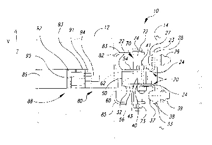
Figure I is a top view of a connector in accordance with the invention
attached to an exhaust pipe and a truck.
2 ~ 79475
3
Figure 2 is a side elevational view of a connector in accordance with the
invention.
Figure 3 is a top elevational view of the connector of Figure 2.
Figure 4 is a cross section view of a resilient member and a rigid bushing
in accordance with the invention.
Detailed Description of the Invention
Figures 1-4 illustrate a connector 10 for mounting a vertical exhaust
pipe 12 to a wall 14 of a truck cab. Like reference numbers refer to like
parts
throughout the various figures.
Figure 1 illustrates the connector 10 securing an exhaust pipe 12 to the
wall 14 of a truck cab 18. The exhaust pipes 12 and cab IH are separately
mounted to
two longitudinal members 16 and 17 that make up part of the frame of the truck
cab 18.
A muffler 15 is rigidly mounted to the frame member 17 so that the general
motion of
the frame member 17 is imparted to the exhaust pipes 12. The cab 18, however,
is
mounted to a separate air suspension system (not shown) on the frame members
16 and
17 to provide a smoother ride. Accordingly, the cab 18 and exhaust pipes 12
often
move in different directions with respect to one another, causing substantial
lateral
displacement (indicated by the arrows L) between the exhaust pipes 12 and cab
walls 14.
A significant amount of vertical displacement also occurs between the exhaust
pipe 12
and cab wall 14. Such vertical displacement is in a direction that is
perpendicular to the
plane defined by the arrows L. The connector 10 allows a significant amount of
vertical
displacement to occur between the exhaust pipe 12 and cab wall 14, while
substantially
preventing lateral displacement therebetween. The connector 10 also dampens
the
vibrations of the exhaust pipe 12 to reduce the amount of noise in the cab I
8.
Figures 2 and 3 illustrate one embodiment of the connector 10. The
connector 10 includes a bracket 20, a resilient member 50, a rigid bushing 60,
a rod 70,
and a clamp 80. The bracket 20 has an upper flange 22 with a horizontal leg 24
and a
vertical foot 23, and a lower flange 32 with a horizontal leg 34 and a
vertical foot 33.
The upper flange 22 is attached to the wall 14 by a number of bolts 27 and
nuts 29. The
bolts 27 extend through the foot 23 and wall 14, and a nut 29 is threadedly
attached to
each bolt 27. The lower flange 32 is similarly attached to the wall 14 by a
number of
bolts 37 and nuts 39. A first washer 28 is placed between the upper foot 23
and wall 14,
and a second washer 38 is placed between the lower foot 33 and wall 14. The
washers
28 and 38 may be made from rubber or other similarly deformable material to
dampen
vibrations from the flanges 22 and 32 and to protect the wall 14 from being
scratched by
z' T94 ~~
4
the bracket 20. Each flange 22 and 32 has a large hole 25 positioned through
its leg for
receiving a portion of the resilient member 50.
The upper and lower flanges 22 and 32 are spaced apart by a spacer 40.
In one embodiment, the spacer includes a sleeve 43 and a bolt 41 positioned
through a
hole (not shown) in the sleeve 43. The sleeve 43 is positioned between the
opposing
surfaces of the upper and lower flanges 22 and 32, and the bolt 41 is
positioned through
small holes in the flanges and the opening in the sleeve 43. A nut 42
threadedly engages
the lower portion of the bolt 41 to urge the upper and lower flanges 22 and 32
against
the ends of the sleeve 43. The space between the opposing surfaces of the
upper and
lower flanges 22 and 32, therefore, is defined by the length of the sleeve 43.
In a
preferred embodiment, a spacer 40 is positioned on either side of the
resilient
member 50.
The resilient member 50 is positioned in the space between the upper and
lower flanges 22 and 32. Referring to Figure 4, the resilient member 50 has a
central
body portion 52 from which an upper boss 54 extends upwardly and a lower boss
56
extends downwardly. The body 52 has an upper shoulder 55 around the upper boss
54
and a lower shoulder 57 around the lower boss 56. In a preferred embodiment,
the body
also has a kerf 58 positioned around its interior. The resilient member 50 is
made from a
deformable material that has good vibration dampening characteristics and is
suffciently
durable to consistently return to its original shape after minor deformations.
In a
preferred embodiment, the resilient member 50 is made from a cast polyether-
based
thermoset polyurethane having a hardness of about 40-70 Shore A.
The rigid bushing 60 is coupled to the resilient member 50. The resilient
member 50 and rigid bushing 60 are preferably coupled together by molding the
resilient
member 50 around the rigid bushing 60 so that the two parts become a single
piece.
The rigid member 60 has an outer wall 64, an inner wall 63, and a hole 62 that
is defined
by the inner wall 63. The hole 62 is generally positioned to extend vertically
through the
rigid bushing 60. In a preferred embodiment, an annular shoulder 66 extends
around the
outer wall 64, and the rigid bushing 60 is coupled to the resilient member 50
so that the
annular shoulder 66 is positioned within the kerf 58. The upper and lower
edges of the
rigid bushing 60 are preferably flush with the surfaces of the upper boss 54
and the
lower boss 56, respectively. The rigid bushing 60 is preferably made from a
hard
material that has self lubricating particles, such as graphite, embedded in
its structure.
One type of suitable material is an acetyl copolymer such as Delrin~,
manufactured by
DuPont de Nemours, Inc.
The scope of the invention is not limited to the specific materials
disclosed above, and other suitable materials may be used to make the
resilient
X179475
member 50 and the rigid bushing 60. The scope of the invention is also not
limited to
the configuration of the resilient member 50 and rigid bushing 60 shown in
Figure 4.
The resilient member SO and rigid bushing 60 may be shaped differently and may
be
coupled together by mechanical or other adhesive means. The central aspects of
the
invention with respect to the resilient member are that it be made from a
deformable,
vibration dampening material, and that it be coupled to the rigid bushing in a
manner
that separates the cab 18 from the vibrations of the exhaust pipe 12.
Refernng to Figures 2-4, the resilient member 50 is positioned in the
space between the upper and lower flanges 22 and 32 so that the upper boss 54
extends
through the hole 25 in the upper flange 22 and the lower boss 56 extends
through the
hole 25 in the lower flange 32. The body 52 preferably has a thickness that is
slightly
greater than the length of the sleeve 43. Accordingly, the lower surface of
the leg 24
abuts the upper shoulder 55, and the upper surface of the leg 34 abuts the
lower
shoulder 57. The resilient member 50 is slightly compressed as the nuts 42 are
tightened
until the opposing faces of the upper and lower flanges 22 and 32 abut the
ends of the
sleeves 43. Accordingly, the spacer 40 acts to maintain the appropriate
distance
between the upper and lower flanges 22 and 32, and to ensure that the
resilient member
50 is coupled securely to the flange 20.
Referring again to Figures 2 and 3, the clamp 80 includes a brace 82 and
a clasp 88. The brace 82 is preferably a C-shaped channel member with an upper
finger
83, a back 84, and a lower finger 85. The clasp 88 is preferably a band 89
that is
coupled to the back 84. The ends of the band 89 are formed into a first tab 92
and a
second tab 93, and fitting 90 is attached to the first tab 92. A stud 94
extends from the
fitting 90 through the second tab 93, and nut 91 is threadedly attached to the
stud 94.
By rotating the nut 91 about the stud 94, the tabs 92 and 93 are drawn
together to
fixedly secure the band 89 to the exhaust pipe 12. When the nut 91 is
sufficiently
tightened, the friction between the band 89 and exhaust pipe 12 fixedly
attaches the
clamp 80 to the pipe 12 so that there is no relative movement between the
clamp 80 and
the pipe 12.
A rod 70 is attached to the fingers 83 and 85, and it is positioned through
the hole 62 of the rigid bushing 60. The clearance between the rod 70 and the
inner wall
63 is nominal to prevent the rod 70 from moving laterally with respect to the
bushing
60. The rod preferably has a sleeve 74 positioned between the opposing
surfaces of the
upper and lower fingers 83 and 85, and a bolt 72 that is positioned through a
series of
aligned holes in the upper finger 83, sleeve 74, and lower finger 85. A nut 73
is
threadedly attached to the lower portion of the bolt 72 to draw the upper and
lower
fingers 83 and 85 towards each other into contact with the ends of the sleeve
74. By
~ 1794..75
6
sufficiently tightening the nut 73, the rod 70 is securely attached to the
brace 82 so that
there is no relative movement between the rod 70 and the exhaust pipe 12.
In operation, the rod 70 moves axially through the hole 62 of the rigid
bushing 60 to freely accommodate any vertical displacement between the cab
wall 14
and the pipe 12 (indicated by the arrows V in Figure 2). The rod 70, however,
is
substantially prevented from moving laterally with respect to the exhaust pipe
12 or cab
wall 14 (indicated by the arrows L in Figure 3). Accordingly, by rigidly
facing the
band 89 to the exhaust pipe 12 and rigidly fixing the bracket 20 to the cab
wall 14, the
close tolerance between the rod 70 and the inner wall 63 of the rigid bushing
60
substantially prevents lateral movement between the exhaust pipe 12 and the
cab
wall 14. Some angular displacement is allowed between the rod 70 and the upper
and
lower flanges 23 and 32 by the slight deformability of the resilient member
50. The
angular displacement is necessary because the exhaust pipe and cab tend to
have some
minor angular displacement with respect to one another in addition to the
vertical and
lateral displacement.
Therefore, the connector 10 allows significant vertical displacement
between the exhaust pipe 12 and cab wall 14, while substantially preventing
any lateral
displacement therebetween. The connector 10 also reduces the noise level in
the cab
because it is positioned to isolate the exhaust pipe 12 from the cab 18, and
it is made
from a material that absorbs a significant amount of the vibrations from the
exhaust pipe
12.
In another embodiment of the invention (not shown), the rod 70 may be
attached to the bracket 20, and the resilient member 50 may be coupled to the
brace 82.
As such, the invention encompasses a connector for mounting a vertical exhaust
pipe to
a truck cab that has a bracket, a clamp, and a means for coupling the bracket
to the
clamp that allows for significant vertical displacement between the exhaust
pipe and the
cab while substantially preventing lateral movement therebetween. One such
coupling
means is the device shown in Figures 1-4. Other coupling means include, but
are not
limited to, resilient rolling members that roll within a channel or along a
track. It will be
appreciated that still other coupling means will be within the scope of the
invention so
long as they allow significant vertical displacement between the exhaust pipe
and the cab
while substantially preventing lateral movement therebetween.
From the foregoing, it will be appreciated that, although specific
embodiments of the invention have been described herein for purposes of
illustration,
various modifications may be made without deviating from the spirit and scope
of the
invention. Accordingly, the invention is not limited except as by the appended
claims.