Note: Descriptions are shown in the official language in which they were submitted.
;~ 1 7 9 ~
The present invention relates to a safety device for the
manoeuvring and auxiliary winching of self-propelled vehicles used on
steep slopes.
Purely by way of a non-limiting example, in the description below
specific reference will be made to use of the device for vehicles
employed on snow-covered terrain which are commonly referred to as "snow
cats" or piste beaters; it is understood, however, that the scope of the
invention also extends to use of the device on other types of vehicles.
Snow cats or piste beaters are widely used in skiing resorts in
order to flatten the snow and thus make the snow-covered surface of the
skiinq pistes uniform.
In view, therefore, of the extremely difficult conditions in which
these vehicles are required to operate, they are usually provided with
crawler tracks driven by a suitable motor.
However, the action of the motor alone may not be sufficient to
cope with steep slopes or to keep the vehicle stable should the
underlying snow layer give way. Consequently, the vehicle could sut~fer
serious damages and furthermore, a drawback which is even more serious,
the lives of the persons operating the vehicle could be endangered.
In order to eliminate these drawbacks, the vehicles according to
the known art are provided with a device comprising a manoeuvring arm
fixed to the vehicle freely rotatably about a vertical axis. The
manoeuvring arm has running along it a winching cable, a first end of
which is fixed to the top of the slope to be travelled up, while the
second end is wound around a winding drum driven by a motor.
The device is further provided with braking means designed to
prevent the undesirable reverse rotation of the winding drum, thus
preventing release of the cable coiled up inside the drum itself.
The winching device not only facilitates travel of the vehicle
uphill, but also makes it possible to deal with difficult situations
where manoeuvring would be particularly arduous and dangerous such as,
for example, in the cases described above.
Finally, since the manoeuvring arm is freely rotatable, it is
2 1 79~38
always arranged in the same direction as the winching cable,
independently of the position of the vehicle. Consequently the pulling
force of the cable always passes along the vertical axis of rotation of
the manoeuvring arm, thereby preventing the generation of moments which
could make the vehicle unstable.
The abovementioned winching device, however, has various drawbacks
including those arising from the direct connection between the winching
cable and the winding drum. More specifically, in view of the irregular
nature of the snow layer, the winching cable is frequently subject to
sudden stresses which are correspondingly transmitted onto the winding
drum and which increase the wear of the winching cable. Consequently, on
account of these sudden forces of considerable intensity, the winding
member is subject to a high degree of fatigue with a consequent reduction
in its working life.
A further drawback is due to the fact that, since the cable wound
around the winding drum tends to bunch up rather than be distributed
uniformly over the entire width of the drum, the winding diameter o, the
cable gradually increases by a substantial amount. With a constant speed
of rotation of the winding drum, the linear speed at which the cable is
coiled up around the drum gradually increases and hence, as the vehicle
moves forward, the speed of forward movement of the vehicle must increase
correspondingly in order to prevent the upward pulling force from being
transmitted mainly to the winding drum motor. In practice, the result is
that the vehicle, when it sets off, is moving more slowly than when it
reaches its destination.
Moreover, the cable wound around the drum under great tension is
subject to rubbing forces and, being compressed between the underlying
turns of cable and the overlying turns, becomes flattened. The rubbinq
and deformations wear out the cable and reduce its working life so that
periodic checking and replacement of the cable is required, said
operations being long, laborious and costly.
Considering, moreover, the sometimes sudden stresses to which the
cable is subject, it can be easily understood how the said cable, while
8 ~ ~
winding around the winding drum, tends to become entangled, making it
difficult to perform the reverse operation, i.e. release of the cable
from the winding drum.
A further drawback is caused by the vertical dimensions of the
vehicle since the presence of low overhead obstacles on the skiing pistes
could prevent transportation of these vehicles and moreover, still for
the same reason, could prevent parking of the vehicle in garages with low
ceilings.
Finally, in the case of the devices of the known art, there is an
initial phase of tensioning of the cable during which, following fixing
beforehand of both its ends, if the manoeuvring arm is not aligned with
the cable it ~otates violently about its vertical axis, moving from its
initial position into the position where it is aligned with the cable - a
sudden rotation which can be damaging not only for the winching device,
but also for the persons who might be on or in the vicinity of the
vehicle.
The aim of the present invention, therefore, is to devise and
provide a device in which all the drawbacks mentiGned in connection with
the cited prior art are eliminated, i.e. a device in which both the
intensity of the sudden forces which affect the winding drum and the wear
of the cable is reduced and finally in which winding of the cable around
the winding drum is made uniform and the difference existing between the
starting speed and the speed of arrival of the vehicle is eliminated.
A further aim of the invention is to provide a device which makes
it possible for the vehicle, on which it is mounted, to be transported in
the case where overhead obstacles are present and to be parked in garages
with low ceilings.
Finally, during the phase when the cable is tensioned, the
manoeuvring arm must be prevented from rotating violently out of control
about its vertical axis.
These aims are achieved by means of a device of the type described
in the introduction, i.e. comprising a manoeuvring arm associated with
the vehicle itself and freely rotatable about a vertical axis, a winding
2 1 7q83~
drum operated by drive means and designed to wind at one end a winching
cable running along said arm, while the other end of the cable is fixed
to the top of the slope to be travelled up, said device being further
provided with braking means designed to prevent release of the cable
wound around the winding drum, characterized in that it comprises at
least one guide and traction roller around which the cable is wound with
friction for a plurality of turns before being coiled up by means of
winding around said winding drum, said device being further characterized
in that it comprises a detection and control member designed to detect
the winding radius of the cabie wound around the winding roller and to
adjust the speed of rotation of the winding roller drive means so that
the linear speed with which the cable is coiled up is constant.
In a particular embodiment of the invention, said braking means are
applied to said at least one guide rolier and are designed to prevent
release of the cable wound around the winding drum.
In this way, when a difficult situation occurs in which the power
of the vehicle's engine is not sufficient to oppose the high strain to
which the winching cable is subject, the braking means block rotation of
said at least one roller. The frictional force which develops between
the cable and said at least one guide rGller opposes the strain to which
the cable is subject, preventing release thereof from the winding drum
and therefore preventing the vehicle from moving backwards.
If, however, a particularly difficult situation should occur, such
as for example the negotiation of a hump or the yielding of the
underlying snow layer, the pulling force of the winching cable would
reach the limit value consisting of the frictional force generated
between the cable itself and the guide roller. When this critical value
is reached, the tensile stress tG which the cable is subject does not
increase and the winching cable starts to slip slowly on the guide roller
causing release of the cable wound around the winding drum. In this way,
by limiting the maximum stress to which the cable can be subject, the
probability of breakage of the winching device is reduced and its working
duration is increased.
Finally, slipping of the cable along the guide roller allows the
vehicle to move backwards in a controlled manner and hence move away from
the obstacle encountered. In the new situation, which is decidedly more
favourable, the operator can regain control of the vehicle and hence
start moving again.
In a particular embodiment, said at least one guide roller is
operated by drive means.
The task of coiling up the cable is in this case fulfilled
precisely by said guide roller drive means so that the section of cable
comprised between said at least one guide roller and said winding drum is
stressed by a sufficiently small amount to keep the cable slackened. ~y
so doing, the rubbing forces and compression which the ca~le undergoes
are reduced, limiting wear and flattening of the said cable.
Furthermore, since the speed of rotation of the guide rollers is
constant, the linear coiling speed of the cable is also constant so that
the departure speed of the vehicle and the speed of arrival are the same.
In a further embodiment of the invention said guide rollers are two
and the winching cable is wound alternately around the first and the
second roller inside grooves formed on each of the two guide rollers.
The section of cable when winding around the two guide rollers is
subject to significant stresses, but since the cable is guided inside
grooves, the rubbing action between adjacent turns of the cable is
substantially reduced. Furthermore the rollers are made preferably of
soft material such that the rollers and not the cable are subject to
wear. In this way the checking operations as to the extent of wear and
any replacement of the worn components are simplified considerably.
In another embodiment the device comprises a cable distributor
which performs a transverse movement and is located between said guide
rollers and said winding drum and is designed to allow winding of the
cable such that it is uniformly distributed around the drum itself.
The cable is therefore wound uniformly over the entire width of the
winding drum such that there is a smaller increase in the winding
diameter of the cable so that, with the linear coiling speed of the cable
2~ 79~38
being constant, the number of revolutions of the winding drum will vary
by a smaller amount.
Furthermore the possibility that the cable may become entangled is
reduced to a minimum.
In another embodiment the manoeuvring arm is pivotably mounted
about an axis which is substantially horizontal and parallel to the
longitudinal axis of the vehicle so as to be able to assume a first
operating position in which it is arranged vertically and a second
operating position in which it is tilted horizontally.
Obviously by tilting the manoeuvring arm through 90 fr-om the
vertical position, the vertical dimensions of the vehicle are reduced,
making it possible to park and transport the vehicle even in the presence
of structures with a low ceiling.
Finally, in a further embodiment, the device comprises drive means
and transmission means designed to rotate the manoeuvring arm about its
vertical axis. In this way, after suitably fixing the cable to the
device and firstly tensioning it, by means of these drive means the
manoeuvring arm is positioned so as to align it with the cable. During
the next phase, i.e. during tensioning of the cable, the manoeuvring
cable is not subject to any sudden rotation.
In this way, since the linear coiling speed of the cable is
constant, the starting speed of the vehicle and the speed of arrival are
the same.
These and further characteristic features and advantages of the
invention will emerge more clearly from the following detailed
description, provided by way of a non-limiting example, with reference to
the accompanying drawings in which:
- Figure 1 is a side view of a snow cat comprising a manoeuvring
and auxiliary winching device according to the present invention;
- Figure 2 is a partially sectioned side view of the device
illustrated in Figure 1;
- Fiqure 3 illustrates an enlarged and partially sectioned detail
of Figure 2;
~ 1 l7~ i8 ;~ ~
- Figure 4 is a cross-section through the friction group of the
device shown in Figure 2;
- Figure 5 is a section along the plane indicated by V-V in Figure
4;
- Figure 6 shows, on a larger scale, the cable distributor
illustrated in Figure 2;
- Figure 7 is a longitudinal view of the cable distributor shown in
Figure 5;
- Figures 8 and 9 are two front views of the manoeuvring arm of the
device according to Figure 2, shown in the vertical and horizontal
position, respectively;
- Figure 10 is a partially sectioned side view of a further
embodiment of the snow cat comprising .3 ~onoeuvring and auxilary winching
device according to the present invention;
- Figure 11 is a partially sectioned side view of the device
illustrated in Figure 10;
- Figure 12 illustrates an enlarged detail of the winding drum
according to Figure 11;
- Figure 13 is a cross-section throush the winding drum along the
plane indicated by A-A in Figure 12;
- Figure 14 is a cross-section along the plane indicated by B-B in
Figure 12;
- Figure 15 shows, on a larger scale, the detail of the
transmission means shown in Figure 13;
- Figures 16 and 17 are cross-sections along the lines C-C and D-D
of Figure 6, respectively;
- Figure 18 is a longitudinal view of the cable distributor shown
in Figures 11 and 12.
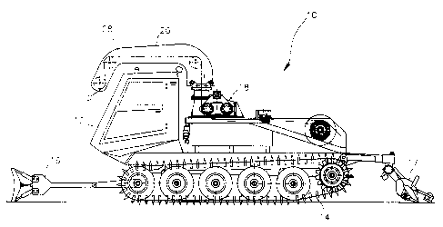
In Figure 1, 10 denotes in its entirety a self-propelled vehicle
used on ski pistes and commonly referred to as a snow cat or piste
beater.
The vehicle 10 comprises a frame or bodywork 12 provided with
crawler tracks 14 which facilitate the uphill travel of the vehicle on
2.~ 798~8
_ 9 _
the ski pistes; furthermore, the vehicle 10 is provided both at the front
and at the rear with smoothing blades denoted by 16 and 17, respectively,
which each have the function of making the snow layer level. Finally,
the frame 12 is provided with a safety device for manoeuvring and
auxiliary winching, denoted overall by 18.
The device 18, as can be seen more clearly in Figure 2, comprises a
manoeuvring arm 20 which extends horizontally and has opposite ends 20a,
20b. The end 20a is fixed to a support 22 which is mounted rotatably,
about a vertical axis Y, on a base 23 rigidly fixed to the frame 12. As
regards initial positioning of the manoeuvring arm 2Q with respect to the
connection between vehicle and the point for fixing of the cable and with
reference to Figure 3, it can be noted that the rotating support 22 is
integral with a toothed wheel 24 which meshes with the pinion 25 integral
with the drive shaft 26. A pair of bearings 29 are located between the
rotating support 22 and the base 23.
The manoeuvring arm 20 is provided with pulleys 27 having, running
over them, a winching cable 28, one end 28a of which is fixed to the top
of the slope to be travelled up. The cable 28 travels first of all over
the pulleys 27 and is then suitably coiled up by the device itself.
For this purpose the device 18 comprises a winding drum 30 operated
by a suitable motor, not shown in the Figures, around which the cable 28
lS wound.
The device 18 comprises, moreover, a friction group, denoted
overall by 32, which is located between the manoeuvring arm 20 and the
winding drum 30 and is provided with two rollers 34 and 36, having
mutually parallel axes, around which the cable 28 is wound for a few
turns in the manner and for the purposes which will be specified below
with reference to Figures 4 and 5, before being wound around the winding
drum 30. Finally, a device 38 for distributing the cable 28, described
in detail below with reference to Figures 6 and 7, is located between the
friction member 32 and the winding drum 30 and has the function of
uniformly distributing the turns of the cable 28 over the surface of the
winding roller 30.
2 ~ 79~3~
- 10 -
A deviating roller 40 is located in a position underlying the
friction group 32 and between the latter and the distributor 38, said
roller having the function of deviating the section of cable emerging
from the friction group 32 so that it does not interfere with the group
itself.
Considering now Figures 4 and 5, it can be noted that the friction
group 32 comprises a hydraulic motor 41, the shaft of which is provided
with a pinion 42 meshing with a toothed wheel 44. The toothed wheel 44
is locked in rotation with the central or sun gear 46 of an epicyclic
reducer 48. The sun gear 46 is in meshing engagement with three
peripheral or planetary gears 50 of the reducer 4& arranged angularly at
the same distance from one another along the external ioothing of the sun
gear 46. The three planetary gear~ 50 mesh with the internal toothing cf
a crown ring 52 provided with an external toothing meshing with two
toothed wheels 54 and 56 locked in rotation with the guide rollers 34 and
36, respectively.
Each guide roller 34 and 36, as illustrated in Figure 5, is
provided with a plurality of grooves 37, preferably seven, inside which
the cable 28 is wound.
The friction group 32 is provided, moreover, for each guide roller
34 and 36, with a hydraulic lamellar safety brake of the commercial type,
denoted overall by 56 and having the function of blocking reverse
rotation of the rollers 34 and 36, preventing release of the cable 28
wound around the winding drum 30.
Figures 6 and 7 illustrate, on the other hand, the cable
distributor 38 which has the function of allowing the cable 28 to be
wound uniformly over the entire width of the winding drum 30. The
distributor 38 comprises a screw 58 with a left-hand thread 58a and a
right-hand thread 58b with one of which there engages a half-crown ring
60 integral with an element 62 for guiding the cable 28, any rotation of
which about the screw 58 is prevented. The guide element 62 comprises a
first and a second pair of rollers denoted by 64 and 66, respectively; in
each pair 64, 66 the rollers are arranged opposite one other and the
9838
cable 28 emerging from the friction group 32 passes between them. The
axes of the pair of rollers 64 are parallel to the axes of the guide
rollers 34 and 36 of the friction group 32, while the axes of the pair of
rollers 66 are rotated through 90 , with respect to the axes of the pair
of rollers 64, about the section of cable 28 emerging from the friction
group 32.
When the screw 58 is made to rotate by the winding drum 30 via a
special mechanical coupling, not illustrated in the Figures, the
half-crown ring 60 and hence the guide element 62 are displaced along the
screw 58 in the direction which depends on the type of threading in which
the half-crown ring 60 is engaged. Once the end of the screw 58 has been
reached, the half-crown ring 60 stops and engages with the other
threading, then travelling along the screw 58 in the opposite direction
to the the previous one, until it reaches the other end of the screw
where a further reversal of the movement occurs.
Obviously the length of the screw 58 is equal to the axial
extension of the winding drum 30 so that the cable is coiled up over the
entire surface of the drum. For uniform winding at each revolution of
the winding drum 30, the distribution device 38 must move a distance
equivalent to the diameter of the cable so that, if for example the pitch
of the threads of the screw 58 is equal to the diameter of the cable 281
one turn of the screw 58 must correspond to each revolution of the
winding drum 30.
In Figures 2, 8 and 9, finally, it can be noted that the end 20a of
the manoeuvring arm 20 is fixed to the support 22 so as to allow a
rotation of the arm itself around a horizontal axis X. More precisely,
the end 20a has fixed to it a bracket 68 with two holes 70,72, the axes
of which are aranged parallel to the manoeuvring arm 20. The support 22,
on the other hand, is provided with two lugs 74,76 in each of which a
hole is formed. The bracket 68 i5 hingeably mounted on the support 22 by
means of a pin engaging in the hole 70 of the bracket 68 and in the hole
of the lug 74. When the manoeu~ring arm 20 is arranged vertically (see
Figure 8), the bracket 68 is fixed to the support 22, engaging a pin in
8 ~ 8
- 12 -
the hole 72 of the bracket 68 and in the hole of the lug 76.
Operation of the device is as follows:
First of all one end 28a of the cable 28 is fixed to the top of the
slope, while the second end is passed over the pulleys 27 of the
manoeuvring arm 20. The cable 28 is wound around the two guide rollers
34, 3~, being slidably housed inside the grooves 37 and passing
alternately from one roller to the other.
The cable 28 is then passed over the deviating roller 40 and then
into each of the pair of rollers 64 and 66 of the distributor 38;
finally, the second end is fixed to the winding drum 30.
At this point, by means of the motor 26, the manoeuvring arm 20 is
made to rotate about its vertical axis Y so as to align it with respect
to the cable 28.
Then the hydraulic motor 41 driving the friction group 32 and the
motor driving the winding drum 30 are started up until the cable 28 is
tensioned. At this point the vehicle 10 is able to start travelling up
the slope, while the cable 28 is coiled around the winding drum 30. At
the same time the screw 58 of the distributor 38 is made to rotate so
that the cable 28 is coiled up uniformly around the winding drum 30, thus
limiting substantially the variation in the winding diameter of the cable
between the moment of departure and arrival.
When a particularly difficult situation arises, such as for example
the negotiation of a hump or the yielding of the underlying snow layer,
where the pulling force of the winching cable exceeds the force generated
by the motor 41, the lamellar brakes 56 intervene in order to block the
rollers 34 and 36, preventing them from rotating in the opposite
direction and hence the winding drum 30 from releasing the cable 28.
Consequently the vehicle is prevented from moving backwards or, even
worse, from sliding down the slope and endangering the lives of its
occupants.
If, however, the pulling force of the cable 28 reaches the limit
value consisting of the frictional force generated between the cable
itself and the guide rollers 34 and 36, the winching cable starts to slip
~ ~ 7~8~8
slowly on the guide rollers which are blocked.
The slipping of the cable 28 over the guide rollers 34 and 36
allows the vehicle 10 to reverse and hence move away from the obstacle
encountered.
The friction group 32 therefore functions as a means for limiting
the stress to which the cable 28 and the device 18 are subject, thus
preventing possible breakages caused by sudden and intense forces which
may be generated following circumstances such as those described above.
On the other hand, if the vehicle 10 should need to be transported,
passing underneath low bridges, or be parked in garages with low
ceilings, it is sufficient, starting from the operating condition shown
in Figure 8, to disengage the fixing pin from the hole of the lug 76 and
from the hole 72 of the bracket 68 and tilt the manoeuvring arm 20
(Figure 9) through 90 .
Moreover, the device can also be used for the downhill travel of
the vehicle, during which, instead of coiling up the winching cable, it
has the function of releasing it from the winding drum.
In the case where the motor itself of the vehicle is not able to
ensure a uniform descent of the vehicle or should the layer of snow give
way, the device prevents the vehicle from reversing suddenly, keeping the
speed of descent more or less constant. If the tensioning force of the
cable should reach such a value that the hydraulic motor of the device is
unable to guarantee a uniform descent, the brakes or lamellae will enter
into operation in order to block the guide rollers so that the tensioning
force is opposed by the friction between cable and guide rollers. If, on
the other hand, the force is very high, the cable slips around the
rollers so that the vehicle moves back slowly until it reaches a stable
position.
Finally it is possible to use the device in the condition where the
guide rollers are blocked, allowing the vehicle to move sideways in total
safety.
The device according to the invention may be subject to changes
conceptually equivalent without departing from the scope of the present
21 ~9~338
- 14 -
invention.
For example, instead of providing two guide rollers around which
the winching cable is wound beforehand, it is possible to have only one
roller; or also, instead of providing a plurality of circular grooves
arranged alongside one another, it is possible to provide a helical
groove for each guide roller.
Referring now to figures 10 to 18 a modified embodiment of the device
according to the present invention is described. In said figures the same
elements of the preceding figures are marked with the same numeral
references and accordingly the description thereof will be omitted.
The device 18 comprises also in this case, a winding drum 30, illustrated
in more detail in Figures 12 and 13, which is operated by a suitable
hydraulic motor ~not shown in the Figures). The winding drum 30
comprises a roller 132, rotating about an axis X', inside which the cable
28 is wound and which is supported at both its axial ends 130a, 130b by
means of bearings 134. At the axial end 130a the winding drum 30 is
provided moreover with a transmission group, denoted overall by 136 and
illustrated in detail below with reference to Figures 15, 16 and 17, to
which a hydraulic drive motor (not shown in the Figures) is connected.
The winding drum 30 is provided with a detection and control member 139
(see Figures 12 and 14) designed to detect the winding radius of the
cable wound around the roller 132 and adjust the speed of rotation of the
hydraulic motor so that the linear speed with which the cable is coiled
up is constant.
Finally, the device 18 is provided with a distributor 138,
described in detail below with reference to Figure 18, which has the
function of uniformly distributing the turns of the cable 28 on the
surface of the roller 132.
Considering now Figures 12 and 14, it can be noted that the
detection and control member 139 comprises a sensing cylinder 140
arranged inside the roller 132 between its walls (132a, 132b) and
rotatably supported at both its ends at the two ends of two arms 142, 144
so as to be rotatable about an axis W parallel to the axis of rotation X'
2 ~ 7 ~ 8
- 15 -
of the roller 132. The length of the cylinder 140 is such that the two
arms 142, 144 are able to slide on the internal surfaces of the two side
walls 132a, 132b of the roller 132. The arms 142 and 144, at the opposite
ends to those supporting the cylinder 140, are pivotably mounted by means
of a pin 146 positioned above the roller 132; consequently the cylinder
140, owing to the force of gravity, remains in contact with the cable 28
wound inside the roller 132 and, as the layers of wound cable increase,
the cylinder 140 is raised while still remaining in contact with the
upper layers of the cable. The cylinder 140 has moreover coupled to it
an electromechanical device, indicated schematically by the reference
number 148, which is designed to detect the position of the cylinder 140
ana adjust the speed of rotation of the hydraulic drive motor of the
winding drum 30 so that the linear coiling speed of the cable is kept
constant. Consequently, as the winding radius of the cable and hence the
number of turns of the wound cable increase, the number of revolutions of
the drive motor is correspondingly reduced. It can be noted that the
cylinder is freely rotatable about its own axis, thus limiting the
friction which is generated between its external surface and the upper
layers of the wound cable.
Examining now Figures 15, 16 and 17, it can be noted that the
transmission group 136 comprises a first and a second epicyclic reducer
denoted by 150 and 152, respectively. The first reducer 150 comprises a
central or sun pinion 153 connected to the shaft of the hydraulic drive
motor and three peripheral or planetary gears 154 arranged angularly at
the same distance from one another along the external toothing of the
central pinion 153. The three planetary gears 154 mesh with the internal
toothing of a crown ring 156 formed on the inside of the casing of the
transmission group 136. The three planetary gears 154 are rotatably
supported on a crown ring 160 provided with an internal toothing meshing
with a central or sun pinion 162 of the second reducer 152. In the
similar manner to the first reducer, the second reducer 152 is further
provided with three peripheral or planetary gears 164 which are arranged
angularly at the same distance along the external toothing of the central
2 l ,7q83~
- 16 -
pinion 162 and which mesh with the internal toothing of the crown ring
156. Finally, the three planetary gears 164 are rotatably supported on
the hub 166 of the roller 132.
Furthermore a hydraulic lamellar safety brake of the commercial
type is provided, said brake being denoted by 170 and having the function
of blocking reverse rotation of the roller 132 so as to prevent release
of the cable 28 wound around it.
Finally, figure 18 illustrates the cable distributor 138 which has
the function of ensuring that the cable 28 is uniformly wound over the
entire width of the roller 132.
The distributor 138 comprises a guide element 172 which moves along
a rectilinear guide 174 arranged parallel to the axis X' of the rGller
132 (see Figure 12). The guide element 172 includes a firs' and a second
pair of rollers denoted by 176 and 178, respectively, the axes of
rotation of which are perpendicular to the axis of rotation X' of the
roller 132 and to the cable 28; in each pair 176, 178, the rollers are
arranged opposite one other and the cable 28 travels between them.
The guide element 172 moves along the guide 174 by means of a
control and operating device, schematically indicated by 180 and known
per se, which, as soon as its detects overlapping of the cable, moves the
guide element 172 over a distance equivalent to the diameter of the
cable, thus ensuring uniform winding of the cable. Obviously, when the
cable has been wound over the entire surface of the roller 132, the
device 180 will cause reversal of the movement of the guide element 172,
thus allowing the cable to be wound in such a way as to form a further
layer.
Operation of the device is as follows;
First of all a first end 28a of the cable 28 is fixed to the top of
the slope, while the second end is passed over the pulleys 27 of the
manoeuvring arm 20.
The cable 28 is then passed through each of the two pairs of
rollers 176 and 178 of the distributor 138 and finally the second end is
fixed to the roller 132 of the winding drum 30.
2 ~ 79~3~
At this point the manoeuvring arm 20 is rotated about its axis of
rotation Y so as to align it with respect to the cable 28.
Subsequently, the hydraulic drive motor of the roller 132 is
started up so as to tension the cable 28.
At this point the vehicle is able to start travelling up the slope,
as the cable 28 is coiled up around the roller 132.
At the same time the distributor 138 is activated so that the cable
28 is uniformely wound up around the roller 132, therefore substantially
limiting the variation in the winding diameter of the cable between the
moment of departure and arrival.
Each time the cable has been uniformely wound over the entire
surface of the underlying cable layer and must therefore be wound so as
to form a new layer, the detection and control member 139 reduces the
speed of rotation of the drive motor of the roller 13~ so as to keep the
linear coiling speed of the cable constant.
Furthermore, the device may be also used for the downhill travel of
the vehicle during which, instead of the coiling up the winching cable,
it has the function of releasing it from the winding drum.
Finally it is possible to use the device in the condition where the
winding drum is blocked, thus allowing the vehicle to be displaced
laterally in total safety.
Finally, it is obvious that any conceptually equivalent
modification or variation falls within the scope of the present
invention.