Language selection

Search

Patent 2179917 Summary

Third-party information liability

Some of the information on this Web page has been provided by external sources. The Government of Canada is not responsible for the accuracy, reliability or currency of the information supplied by external sources. Users wishing to rely upon this information should consult directly with the source of the information. Content provided by external sources is not subject to official languages, privacy and accessibility requirements.

Claims and Abstract availability

Any discrepancies in the text and image of the Claims and Abstract are due to differing posting times. Text of the Claims and Abstract are posted:

  • At the time the application is open to public inspection;
  • At the time of issue of the patent (grant).
(12) Patent Application: (11) CA 2179917
(54) English Title: NOZZLE AND METHOD OF BLOWING HOT METAL
(54) French Title: TUYERE ET PROCEDE DE SOUFFLAGE DE METAL CHAUFFE
Status: Dead
Bibliographic Data
(51) International Patent Classification (IPC):
  • C21C 5/46 (2006.01)
  • C21C 5/48 (2006.01)
  • F27D 3/16 (2006.01)
(72) Inventors :
  • BERGMAN, DAN (Sweden)
  • INOMOTO, TAKEO (Japan)
(73) Owners :
  • MEFOS, STIFTELSEN FOR METALLURGISK FORSKNING (Sweden)
(71) Applicants :
(74) Agent: RIDOUT & MAYBEE LLP
(74) Associate agent:
(45) Issued:
(86) PCT Filing Date: 1994-12-28
(87) Open to Public Inspection: 1995-07-06
Examination requested: 2001-12-06
Availability of licence: N/A
(25) Language of filing: English

Patent Cooperation Treaty (PCT): Yes
(86) PCT Filing Number: PCT/SE1994/001260
(87) International Publication Number: WO1995/018346
(85) National Entry: 1996-06-25

(30) Application Priority Data:
Application No. Country/Territory Date
9304369-3 Sweden 1993-12-30

Abstracts

English Abstract


An annular nozzle for an oxygen lance, e.g. an oxygen lance for blowing steel in a converter, gives an annular hot spot on the liquid
steel in the converter . When exiting the nozzle, the annular jet has disruptions that result in ambient atmosphere being sucked in towards
the centre of the annular jet. Thus, a sub-pressure is prevented which would otherwise prevent the jet from diverging conically. In one
embodiment, the nozzle can be switched during a blowing operation between forming a tight jet and forming a diverging jet.


French Abstract

Tuyère annulaire destinée à une lance à oxygène telle qu'une lance à oxygène utilisée pour souffler de l'acier dans un convertisseur, cette tuyère annulaire produisant un point chaud annulaire sur l'acier liquide présent dans le convertisseur. Lorsqu'il sort de la tuyère, le jet annulaire présente des interruptions qui ont pour effet d'aspirer l'atmosphère ambiante vers le centre dudit jet annulaire. Ceci empêche donc une sous-pression de se développer qui empêcherait le jet de diverger de manière conique. Dans une forme de réalisation, on peut commuter la tuyère pendant une opération de soufflage pour former un jet serré ou un jet divergent.

Claims

Note: Claims are shown in the official language in which they were submitted.


Claims
1 A supersonic annular nozzle for an oxygen lance for metallurgical use,
c h a r a c t e r i z e d by means (19) for permitting a gas supply to the interior
of the formed annular jet in order to counteract a subpressure there.
2 A nozzle according to claim 1,
c h a r a c t e r i z e d in that said means (19) blocks parts of the annular slot
(23) of the nozzle so that the annular jet exiting the nozzle will be divided and
permit ambient gas to flow to the interior of the jet.
3 A nozzle according to claim 2,
c h a r a c t e r i z e d in that it comprises an outer annular body (11) and a cen-
tral substantially conical body (12) which form together the annular slot of thenozzle, and keys (19) and grooves (22) in said bodies form said means for
blocking parts of said annular slot (23), said central body (12) being axially
displaceable so as to permit for a variable slot width, while said keys (19) is still
blocking parts of the slot (23).
4 A supersonic annular nozzle for an oxygen lance for metallurgical use
comprising an outer annular body (11) and a central body (12) which form to-
gether the annular slot (23) of the nozzle,
c h a r a c t e r i z a d in that said central body (12) is displaceable with respect
to said annular body (11) between a first position in which the slot (23) is divi-
ded into separate parts so that the exiting annular jet will be divided into separate
parts and a second position in which the entire annular slot (23) is open so that
the exiting annular jet will be without disruptions.
A nozzle according to claim 4.
c h a r a c t e r i z e d in that said central body (12) is substantially
conical and axially displaceable between its two positions and one of said


bodies (11. 12) has bulbs (19) at the exit end of said slot (23), said bulbs block-
ing said slot when the central body is in its first position but not when it is in its
second position.
6 A method of blowing hot metal with an oxygen lance that has an annular
nozzle,
c h a r a c t e r i z e d in that gas is supplied to the interior of the formed annular
jet in order to counteract a subpressure there.
7 A method according to claim 6,
c h a r a c t e r i z e d in that parts of the annular gas flow exiting the nozzle are
blocked in order to form holes in the annular jet through which ambient
atmosphere can be sucked in.

Description

Note: Descriptions are shown in the official language in which they were submitted.


WO 95/18346 2 ~ PCTISE9410126û
Nozzle and method of blowing hot metal
This invention relates to a supersonic annular nozzie and to a method of blowinghot metal.
Such a nozle is known from GB-1198112. but it seems not to have been inpractical use. A possible cause may be that there will be a ~ui~ u~c in the
middle of the annular jet which tends to hold the jet together so that there will
not be the wide hot spot that is desired.
It is an object of the invention to provide for a method and a nozzle that will
permit a diverging annular jet. It is other objects to provide for an adjustableannular nozzle and to provide for an adjustable annular nozzle that can create
both a tight jet and a diverging jet.
The invention will be described with reference to the dCCUI~ lyillg drawings
that show three annular nozzles in accordance with the invention.
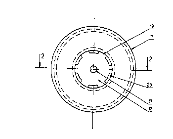
Figure I is an end view of a top blowing nozzle and Figure 2 is a section taken
along the line 2-2 in Figure 1. Figure 3 is an end view of another nozle and
Figure 4 is a section taken along the line 4-4 in Figure 3. Figure ~ is an end view
of still another nozzle and Figure 6 is a section taken along the line 6-6 in Figure
5.
The nozzle shown in the Figures I and 2 comprises an outer body 11 and a cen-
tral body 12 which form a slot 23 between them. The outer body 11 is arranged
to be soldered to the outer and inner tubes 13. 14 of an oxygen lance. In the
annular space between the tubes 13 and 14. there is an ;..Lcl..lc~iidlc tube 1
around which coolirlg water is circulated in a conventional manner. The central
body 12 is fixed to a rod 17 by being screwed to it or soldered to it. The rod 17
extends through the lance.

WO 951183~6 21 7 ~ 91 7 PCT/SE94101260

,
The outer body 11 of the nozzie has a conicai opening 18 and the central body 12of the nozzle is ~ st~nti~lly conical and it has six axial lands or keys 19, with
parallell sides~ that fit the conical opening 18. The nozzle is formed as a super-
sonic nozzle. The keys 19 divide the slot 23 into six parts. which results in holes
in the annular jet at the exit of the nozzle. Ambient gas flows in through theseholes and fills out the ~ui,~,.c ~ that otherwise would occur close to the central
body 12 and prevent the jet from diverging conically. These holes in the jet arefilled and the jet is completely annular when it hits the melt.
In Figures 3 and 4, an alternative embodiment is shown in which the nozzle is
adjustable. The same reference numerals are used as in Figures I and 2 for cor-
responding details. The outer body 11 of the nozzle has three grooves 22 in its
conical surface 18 and the central body 12 has three axial lands or keys 19 thatfit in the grooves 22. The grooves 22 permit axial adjustment of the central body
12 by means of the rod 17 so that the width of the slot 23 between the outer andinner bodies 11, 12 can be varied. The slot 23 is thus divided into three parts.The flow regulation can suitably by carried out with a flow regulator in the con-
duit that leads to the nozzle and the pressure in the conduit can be adjusted byadjustment of the slot width for control of the jet velocity. As a result, the fiow
regulation will be inrl~rl~n~ nt of the axial thermal expansion of the lance and its
rod 17. The relation between the flow rate and the pressure of the oxygen blast
can thus be varied during the refining process, and the wide target area will berrqint:-ir~ The grooves 22 can alLc,~ ,,ly be in the central body 12 and the
keys 19 on the outer body 11.
In Figures ~ and 6 another alternative ~ ,o l;",- : is shown. Its central body 12
has no lands. Instead. its outer body 11 has two lands or bulbs 19 that block only
the exit part of the slot 23. Thus~ the slot 23 is divided into two parts with inter-
mediate blockings 19. This nozzle will give a wide annular hot spot on the melt
as do the previous ~ l o~ However. when the central body 17 is displaced

WQ 95118346 PCT/SE94/0~260
~179~17

inwardly by mcans of the rod 17. there will be no disruptions in the annular slot
23 and thus. no disruptions in the annular flow exiting the nozzle. As a result,there will be a ~ul,~ in the centre of the annular jet and the jGt will
contract and give a small hot spot on the melt. This nozzle makes it possible toimpinge on the metal bath with a wide annular low velocity jet and with a nar-
row high velocity jet during various phases of the same blowing operation.
As an alternative to forrning holes in the jet for counteracting a ~ub!~e~au~i
against the central body 12, gas can be supplied from the end of the lance
through the rod 17 and the central body 12. The gas flow supplied in this way
must probably be of the same order of magnitude as the flow through the nozzle.
and the illustrated ~ oli...~,..l is preferable. A r~mhi~tion of holes in the jet
and a gas supply through the rod 17 and the central body 12 is also possible, and
may be ad~ _ L A i b~ru~ e~ rod 17 can be used also for supplying pul-
verulent material suspended in a gas or liquid.
The nozzles and the lance described can be used in BOS (Basic Oxygen Steel-
making) and in other ml~t~ 5;.,al processes in which a top blowing lance is
used.

Representative Drawing
A single figure which represents the drawing illustrating the invention.
Administrative Status

For a clearer understanding of the status of the application/patent presented on this page, the site Disclaimer , as well as the definitions for Patent , Administrative Status , Maintenance Fee  and Payment History  should be consulted.

Administrative Status

Title Date
Forecasted Issue Date Unavailable
(86) PCT Filing Date 1994-12-28
(87) PCT Publication Date 1995-07-06
(85) National Entry 1996-06-25
Examination Requested 2001-12-06
Dead Application 2003-12-29

Abandonment History

Abandonment Date Reason Reinstatement Date
2002-12-30 FAILURE TO PAY APPLICATION MAINTENANCE FEE

Payment History

Fee Type Anniversary Year Due Date Amount Paid Paid Date
Application Fee $0.00 1996-06-25
Maintenance Fee - Application - New Act 2 1996-12-30 $100.00 1996-12-13
Registration of a document - section 124 $0.00 1997-01-16
Maintenance Fee - Application - New Act 3 1997-12-29 $100.00 1997-12-01
Maintenance Fee - Application - New Act 4 1998-12-29 $100.00 1998-12-21
Maintenance Fee - Application - New Act 5 1999-12-28 $150.00 1999-12-06
Maintenance Fee - Application - New Act 6 2000-12-28 $150.00 2000-12-14
Maintenance Fee - Application - New Act 7 2001-12-28 $150.00 2001-11-26
Request for Examination $400.00 2001-12-06
Owners on Record

Note: Records showing the ownership history in alphabetical order.

Current Owners on Record
MEFOS, STIFTELSEN FOR METALLURGISK FORSKNING
Past Owners on Record
BERGMAN, DAN
INOMOTO, TAKEO
Past Owners that do not appear in the "Owners on Record" listing will appear in other documentation within the application.
Documents

To view selected files, please enter reCAPTCHA code :


To view images, click a link in the Document Description column. To download the documents, select one or more checkboxes in the first column and then click the "Download Selected in PDF format (Zip Archive)" or the "Download Selected as Single PDF" button.

List of published and non-published patent-specific documents on the CPD .

If you have any difficulty accessing content, you can call the Client Service Centre at 1-866-997-1936 or send them an e-mail at CIPO Client Service Centre.


Document
Description 
Date
(yyyy-mm-dd) 
Number of pages   Size of Image (KB) 
Representative Drawing 1997-06-23 1 4
Claims 1995-07-06 2 35
Cover Page 1996-10-02 1 11
Abstract 1995-07-06 1 31
Description 1995-07-06 3 75
Drawings 1995-07-06 3 47
Fees 2001-11-26 1 32
Fees 1999-12-06 1 53
Assignment 1996-06-25 9 383
PCT 1996-06-25 8 326
Prosecution-Amendment 2001-12-06 1 59
Fees 1998-12-21 1 53
Fees 2000-12-14 1 51
Fees 1997-12-01 1 53
Fees 1996-12-13 1 72