Language selection

Search

Patent 2180037 Summary

Third-party information liability

Some of the information on this Web page has been provided by external sources. The Government of Canada is not responsible for the accuracy, reliability or currency of the information supplied by external sources. Users wishing to rely upon this information should consult directly with the source of the information. Content provided by external sources is not subject to official languages, privacy and accessibility requirements.

Claims and Abstract availability

Any discrepancies in the text and image of the Claims and Abstract are due to differing posting times. Text of the Claims and Abstract are posted:

  • At the time the application is open to public inspection;
  • At the time of issue of the patent (grant).
(12) Patent: (11) CA 2180037
(54) English Title: CULTIVATING TOOL
(54) French Title: INSTRUMENT ARATOIRE
Status: Expired and beyond the Period of Reversal
Bibliographic Data
Abstracts

English Abstract


A manually operable tool for cultivating the surface of the earth,
the tool including an elongate handle, a blade including a sharp
toothed forward cutting edge mounted on the handle so that the blade
may be pushed through the earths surface for the eradication of
unwanted vegetation, the blade normally has a centrally located most
forwardly formed cutting tooth and a side tooth disposed on each side
of the most forwardly formed tooth, each of the side teeth include a
"V" notch on an edge facing the centrally located cutting tooth for
selective severing, the blade further provides for the mounting of
an adjustable furrow tooth.


French Abstract

Outil manuel pour cultiver la terre, comprenant un manche allongé, une lame, dont le bord de coupe avant présente des dents acérées, montée sur le manche de sorte qu'elle puisse être enfoncée dans la terre pour en extirper la végétation non désirée. La lame présente habituellement une dent coupante centrale en sa partie la plus avant et deux dents coupantes latérales, une de chaque côté de la dent centrale, portant une encoche en V sur le bord en face de la dent centrale pour la coupe sélective. Une dent ouvreuse réglable peut être montée sur la lame.

Claims

Note: Claims are shown in the official language in which they were submitted.

The embodiments of the invention in which an exclusive property
or privilege is claimed are defined as follows:
1. A hand manipulable earth working tool comprising in
combination, a planar severing blade having a sharp forward
edge, an elongate grasping means, means for mounting said
planar serving blade to said elongate grasping means in a
forward direction so that said planar severing blade is
pushed through said earth in operation, teeth formed on said
planar severing blade each of which includes a portion of
said sharp forward edge, at least one of said teeth is
formed in a most forwardly central location of said planar
severing blade, said teeth further including side teeth one
on each side of said centrally located tooth, all of said
teeth being formed by the intersection of straight edges,
said side teeth each having one edge parallel to said
elongate grasping means.
2. The combination as claimed in claim 1 wherein said means for
mounting said planar severing blade to said elongate grasping
means is a yoke integrally joined to said planar severing
means at each of said side teeth.
3. The combination as claimed in claim 1 wherein said parallel
edges are blunt edges furthest from said centrally located
tooth.

4. The combination as claimed in claim 1 wherein at least one
of said side teeth includes a "V notch" for specific
plant severing.
5. The combination as claimed in claim 1 further including a
mounting aperture in said planar severing blade and an
adjustable furrow tooth mounted in said mounting aperture.

Description

Note: Descriptions are shown in the official language in which they were submitted.


'- 2180037
CULTIVATING TOOL
FIELD OF INVENTION
The present invention relates to a push type hand operated device
for cultivating the ground mainly for the purpose of the eradication
of unwanted vegetation such as weeds and grass.
BACKGROUND OF THE INVENTION
From the beginning of desirable plant growth there was always the
problem of making conditions ideal to maximize the return on the
effort expended. one of the ideal conditions is the absence of
10 undesirable plants commonly called weeds. One solution to the
problem has been the manual grasping and pulling of these weeds.
Other means have been provided such as various forms of the common
hoe and cultivator fingers. The push type device is considered far
superior to the hoe type due to its utilization of ones body weight
to push it instead of a back breaking chopping action. A further
advantage is the accuracy involved. A chopping hoe action invariably
chops off some desirable plants while the push type can be operated
adjacent the desirable plants with accurate selected severance.
The prior art is replete with various types of assorted agricultural
20 hand implements operable to perform assorted weeding and other soil
cultivating tools. The most relevant art known to applicant is in
the form of Canadian Patents 3369 and 349092 and United States
patents 3,797,581 and 4,901,801. The following discussion will
clearly illustrate how applicants device differentiates from, and is
superior to, the devices taught in the patents.

- 2180037
Canadian patent "369" requires an inaccurate chopping action, a
diametrically opposite direction of operational action causing a
stressfull back breaking effort, a structure that prevents cutting
adjacent a solid fixture, a structure that does not have a central
projecting cutting area that makes for ease of operation and a
selective cutting notch in one of the teeth.
Canadian patent "092" includes slots that are narrower at the
forward edge thus preventing entry of unwanted vegetation for
severance, a structure that does not have a continuous cutting edge,
10 a structure that does not have a central projecting cutting area
that makes for ease of operation and a selective cutting notch in
one of the teeth.
United States Patent ~581~ requires an inaccurate chopping action,
a diametrically opposite direction of operational action of the
invention herein described therefore resulting in a stressful back
breaking effort, a structure that prevents cutting adjacent a solid
fixture on one side, a structure that does not have a central
projecting cutting area that makes for ease of operation and a
selective cutting notch in one of the teeth.
United States Patent "801" includes slots formed by blunt teeth phat
are all of the same length, a structure that does not have a
continuous forward cutting edge, a cutting edge on the outer edge
of the side teeth~a structure that does not have a central
projecting cutting area that makes for ease of operation and a
selective cutting notch in one of the side teeth.

2180037
SUMMARY OF THE INVENTION
To overcome the shortcomings of all the known prior art applicant
has provided a hand manipulable earth working hoe or cultivating
implement for the easy removal of unwanted vegetation. What has
been provided is a planar severing blade means having a
continuous sharp undulating cutting edge means forward of an
attached elon~ate handle means so that the severing blade in
operation is pushed forward through the earth. The continuous
sharp undulating cutting edge is formed of several pointed teeth
10 at least one of which is formed as part of the planar severing
blade in a most forwardly central location and two of which are
formed one on each side of the at least one tooth formed in the
most forwardly central location. The two side teeth generally
have included in their cutting edge a "V" notch for specific
plant severing. Provision is also made for the mounting of an
adjustable seed furrow opener.
Therefore the principle object of the instant invention is to
provide an effective tool that is easily manipulable by hand.
A further object of this invention is the provision of a tool
20 that has a continuous toothed sharp edge blade with a central
projecting portion for ease of operation.
A further object of the invention is the provision of a tool
that can be selectively operable to remove such as dandelions
from a lawn.

2180037
Another object of this invention is the provision of a tool that
is simple, durable, and inexpensive to manufacture.
A further object of this invention is the provision of a weeding
or earth working tool that is accurately controllable during
operation by a forward pushing motion.
A further object of this invention is the provision of a tool that
can also operate as a furrow opener for proper seed depth.
BRIEF DESCRIPTION OF THE DRAWINGS
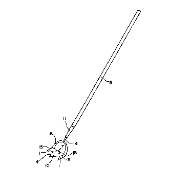
Fig. 1 is a perspective view of the present invention.
~0 Fig. 2 is an end elevation of the cutting blade with the
adjustable seed furrow tooth threadedly attached thereto.
Fig. 3 is a plan view of a modified cutting blade.
DETAILED DESCRIPTION OF THE PREFERRED EMBODIMENT
Referring to figure 1 there is shown the instant invention where
the reference numeral 5 indicates an elongate manipulating handle
means generally made of wood but which may be made of other
material such as aluminum or plastic. One end of the handle means
5 has a ferrule 11 attached thereto. The ferrule 11 usually
prevents splitting of the handle 5 if made of wood when stem 14
20 with yoke attaching means 6 connected thereto is inserted into the
handle 5. The yoke attaching means 6 may be replaced by an
elongate stem 14 directly and centrally attached to severing means
in the form of blade 3 however yoke 6 is preferable for strength
and stability.

2180037
To the yoke 6 is fixed, generally by welding, the severing blade
means 3 which is substantially planar in form and offset from the
plane of the yoke 6. The forward portion of the severing blade
means 3 is in the form of an undulating sharp cutting edge means 4
which is preferably but not necessarily continuous. The share
cutting edge 4 can form several teeth but preferably there is a
most forward tooth 10 formed in a central portion of the cutting
edge 4, and two side teeth 1, one on each side of the central most
forward tooth 10. The side teeth 1 have an outer edge 15 which
10 is not sharpened so that one can make a cut close to desirable
plants without their destruction. A cut close to a wall or fence
is also possible with the undesirable vegitation being forced
toward the sharp cutting edge 4 on the inner edge of tooth 1.
The outer edges 15 of teeth 1 are parallel to the elongate handle
means 5. To the rear of the severing blade means 3 are threaded
aperture means 7 to receive a furrow tooth mounting plate 9 shown
.in.f.igure-2. - . : :.
Referring now to figure 2 there is shown an end elevation of the
severing blade means 3 which is normally made of a hard wearing
20 steel so that it maintains an effective undulating cutting
edge 4. The central most forward tooth 10 is shown projecting
forwardly of side tooth 1 with a blunt side edge 15 which is
parallel to handle 5. Yoke means ~ is not shown here for the sake
clarity. In the threaded aperture means 7 shown in figure l is
mounted a furrow tooth mounting plate 9 secured by fastening

2lson37
means 12. An adjustable furrow tooth 8 is threadably mounted
in the furrow tooth mounting plate 9, adjusted and then locked
by lock nut 13. The adjustable furrow tooth 8 may of course be
adjustably threaded directly in threaded aperture means 7 and as
before locked by lock nut 13.
Refe;-ring now to figure 3 we again have the basic severing blade
means 3 with its undulating sharp cutting edge means 4. The
cutting edge 4 takes the form again of the central most
forwardly tooth 10 and the two side teeth 1 with blunt edges 15.
10 The threaded apertures 7 are again shown and the yoke 6 attached
to the blade means 3 is only partially shown. The severing blade
means 3 has here been modified to enhance its ability to sever
selectively by the addition of a ~'V" notch 2 formed on the
inwardly facing edges of teeth 1. This feature has been found
most useful in removing dandelions from a lawn.
During the operation of this tool when extremely ~lard ground is
er.countered it may be advantageous to use only an end portion of
the cutting edge until the ground has been loosened. Edging of
lawn grass around a garden, tree or the like can also be quite
20 satisfactorlly accomplished when desired. A single tooth 1 with
"V" notch 2 of course is used in the removal of dandelions. It
is to be realized that the operational working movement and
resulting accuracy of this invention is diametrically opposite
to that of the standard hoe. The operation and results bear
no comparison to the prior art.

2180037
Although the invention has been herein shown and described in
what is conceived to be the most practical and preferred
embodiment, it is recognized that departure may be made therefrom
within the scope of the invention which is not to be limited to
the illustrative details disclosed.

Representative Drawing
A single figure which represents the drawing illustrating the invention.
Administrative Status

2024-08-01:As part of the Next Generation Patents (NGP) transition, the Canadian Patents Database (CPD) now contains a more detailed Event History, which replicates the Event Log of our new back-office solution.

Please note that "Inactive:" events refers to events no longer in use in our new back-office solution.

For a clearer understanding of the status of the application/patent presented on this page, the site Disclaimer , as well as the definitions for Patent , Event History , Maintenance Fee  and Payment History  should be consulted.

Event History

Description Date
Time Limit for Reversal Expired 2005-06-27
Inactive: Adhoc Request Documented 2005-03-31
Letter Sent 2004-06-28
Inactive: orrespondence - Final fee 1999-06-02
Grant by Issuance 1998-06-16
Inactive: Final fee received 1998-01-20
Pre-grant 1998-01-20
Letter Sent 1997-12-16
Notice of Allowance is Issued 1997-12-16
Inactive: Status info is complete as of Log entry date 1997-12-08
Inactive: Application prosecuted on TS as of Log entry date 1997-12-08
Inactive: Approved for allowance (AFA) 1997-11-18
Application Published (Open to Public Inspection) 1996-12-28
All Requirements for Examination Determined Compliant 1996-06-27
Request for Examination Requirements Determined Compliant 1996-06-27

Abandonment History

There is no abandonment history.

Maintenance Fee

The last payment was received on 1998-05-27

Note : If the full payment has not been received on or before the date indicated, a further fee may be required which may be one of the following

  • the reinstatement fee;
  • the late payment fee; or
  • additional fee to reverse deemed expiry.

Patent fees are adjusted on the 1st of January every year. The amounts above are the current amounts if received by December 31 of the current year.
Please refer to the CIPO Patent Fees web page to see all current fee amounts.

Fee History

Fee Type Anniversary Year Due Date Paid Date
Final fee - small 1998-01-20
MF (application, 2nd anniv.) - small 02 1998-06-29 1998-05-27
MF (patent, 3rd anniv.) - small 1999-06-28 1999-04-20
MF (patent, 4th anniv.) - small 2000-06-27 2000-04-25
MF (patent, 5th anniv.) - small 2001-06-27 2001-06-01
MF (patent, 6th anniv.) - small 2002-06-27 2002-06-27
MF (patent, 7th anniv.) - small 2003-06-27 2003-04-11
Owners on Record

Note: Records showing the ownership history in alphabetical order.

Current Owners on Record
GARNET L. GILLESPIE
Past Owners on Record
None
Past Owners that do not appear in the "Owners on Record" listing will appear in other documentation within the application.
Documents

To view selected files, please enter reCAPTCHA code :


To view images, click a link in the Document Description column. To download the documents, select one or more checkboxes in the first column and then click the "Download Selected in PDF format (Zip Archive)" or the "Download Selected as Single PDF" button.

List of published and non-published patent-specific documents on the CPD .

If you have any difficulty accessing content, you can call the Client Service Centre at 1-866-997-1936 or send them an e-mail at CIPO Client Service Centre.


Document
Description 
Date
(yyyy-mm-dd) 
Number of pages   Size of Image (KB) 
Claims 1997-11-04 2 40
Description 1996-10-02 7 227
Abstract 1996-10-02 1 17
Claims 1996-10-02 3 96
Drawings 1996-10-02 1 10
Representative drawing 1998-05-11 1 3
Commissioner's Notice - Application Found Allowable 1997-12-15 1 164
Notice: Maintenance Fee Reminder 1998-03-29 1 120
Notice: Maintenance Fee Reminder 1999-03-29 1 119
Notice: Maintenance Fee Reminder 2000-03-27 1 119
Notice: Maintenance Fee Reminder 2001-03-27 1 119
Notice: Maintenance Fee Reminder 2002-03-27 1 121
Notice: Maintenance Fee Reminder 2003-03-30 1 122
Notice: Maintenance Fee Reminder 2004-03-29 1 118
Maintenance Fee Notice 2004-08-22 1 172
Second Notice: Maintenance Fee Reminder 2004-12-29 1 117
Notice: Maintenance Fee Reminder 2005-03-29 1 119
Fees 2003-04-10 1 121
Fees 2000-04-24 1 67
Fees 2001-05-31 1 112
Fees 2002-06-26 1 108
Correspondence 1998-01-19 2 96
Fees 1998-05-26 1 70
Correspondence 1999-06-17 2 13
Fees 1999-04-19 2 81
Correspondence 1999-06-01 5 167
Correspondence 1996-09-26 1 22