Language selection

Search

Patent 2180412 Summary

Third-party information liability

Some of the information on this Web page has been provided by external sources. The Government of Canada is not responsible for the accuracy, reliability or currency of the information supplied by external sources. Users wishing to rely upon this information should consult directly with the source of the information. Content provided by external sources is not subject to official languages, privacy and accessibility requirements.

Claims and Abstract availability

Any discrepancies in the text and image of the Claims and Abstract are due to differing posting times. Text of the Claims and Abstract are posted:

  • At the time the application is open to public inspection;
  • At the time of issue of the patent (grant).
(12) Patent: (11) CA 2180412
(54) English Title: METHOD AND APPARATUS FOR PRODUCTION OF THREE DIMENSIONAL COMPONENTS
(54) French Title: METHODE ET APPAREIL POUR LA FABRICATION DE PIECES EN TROIS DIMENSIONS
Status: Expired and beyond the Period of Reversal
Bibliographic Data
(51) International Patent Classification (IPC):
  • B23B 39/02 (2006.01)
  • B23Q 15/00 (2006.01)
  • G05B 19/4099 (2006.01)
(72) Inventors :
  • MARXRIESER, GERHARD (United States of America)
  • ZARZER, ERICH ALEXANDER (Austria)
(73) Owners :
  • AMERICAN GFM CORPORATION
(71) Applicants :
  • AMERICAN GFM CORPORATION (United States of America)
(74) Agent: GOWLING WLG (CANADA) LLP
(74) Associate agent:
(45) Issued: 2005-03-29
(22) Filed Date: 1996-07-03
(41) Open to Public Inspection: 1997-01-18
Examination requested: 2002-08-15
Availability of licence: N/A
Dedicated to the Public: N/A
(25) Language of filing: English

Patent Cooperation Treaty (PCT): No

(30) Application Priority Data:
Application No. Country/Territory Date
08/503,721 (United States of America) 1995-07-17

Abstracts

English Abstract


A system and method for cutting or milling three dimensional parts with
minimal material waste. The system is comprised of a five or six axis machine,
which is equipped with an ultrasonic cutting device and/or a routing unit, and
is
operated by part programs automatically generated by a software system, which
minimizes material waste and creates a toolpath for the three dimensional
parts to be
manufactured.


Claims

Note: Claims are shown in the official language in which they were submitted.


I CLAIM AS MY INVENTION:
1. A device for forming a plurality of three dimensional parts out of a piece
of
material with minimal waste, comprising:
means for defining a three dimensional shape for each part;
at least one tool for cutting said material, said tool having a predefined
cutting width;
means for snapping each shape as a two dimensional contour onto a plane
of said material, and including in said contour said cutting width;
means for nesting the mapped contours to allocate the two dimensional
contours in an optimal manner within said material to minimize the material
not contained
within the resulting three dimensional shapes;
means for operating said tool to cut said material along the contours
determined by said means for mapping and said means for nesting to achieve
each of said
three dimensional parts.
2. A device according to claim 1, wherein said at least one tool comprises a
plurality of tools, each having its own predefined cutting width and including
means for
automatically selecting a desired tool from said plurality of tools.
3. A device according to claim 2, wherein said tools comprise at least one of
an ultrasonic cutter equipped with a knife and a milling tool.
4. A device according to claim 2, wherein said means for selecting a desired
tool comprises an automatic tool changer.

-8-
5. A device according to claim 1, wherein said means for defining
comprises computer aided design software.
6. A device according to claim 1, wherein said means for mapping
comprises mapping software.
7. A device according to claim 1, wherein said means for operating said
tool comprises a three axis machine.
8. A device according to claim 1, wherein said means for operating said
tool comprises a five axis machine.
9. A device according to claim 1, wherein said means for operating said
tool comprises a six axis machine.
10. A device according to claim 1, wherein said means for mapping
comprises means for mapping each shape as a two dimensional contour onto a
plurality of perpendicular planes of said material.
11. A device according to claim 10, wherein said means for mapping
comprises means for mapping each shape as a two dimensional contour onto three
perpendicular planes of said material.

12. A method for cutting a plurality of three dimensional parts out of a piece
of
material with minimal waste with a cutting tool wherein the tool has a
predefined cutting
width, comprising the steps:
defining a three dimensional shape for each part;
mapping each shape as a two dimensional contour onto a plane of said
material, including in the contour said cutting width;
nesting the mapped contours to allocate the two dimensional contours in an
optimal manner within said material to minimize the material not contained
within the
resulting three dimensional shapes;
operating said tool to cut said material along the contours determined during
said mapping and nesting steps to achieve each of said three dimensional
parts.
13. A method according to claim 12, wherein said step of operating said tool
includes automatically selecting a desired tool from a plurality of tools.
14. A method according to claim 13, wherein said step of selecting comprises
selecting at least one of an ultrasonic cutter equipped with a knife and a
milling tool.
15. A method according to claim 13, wherein said step of selecting a desired
tool
comprises using an automatic tool changer.
16. A method according to claim 12, wherein said step of defining comprises
using computer aided design software.

-10-
17. A method according to claim 12, wherein said step of mapping
comprises using mapping software.
18. A method according to claim 12, wherein said step of operating said'
tool comprises using a three axis machine.
19. A method according to claim 12, wherein said step of operating said
tool comprises using a five axis machine.
20. A method according to claim 12, wherein said step of operating said
tool comprises using a six axis machine.
21. A method according to claim 12, wherein said step of mapping
comprises mapping each shape as a two dimensional contour onto a plurality of
perpendicular planes of said material.
22. A method according to claim 12, wherein said step of mapping
comprises mapping each shape as a two dimensional contour onto three
perpendicular planes of said material.

Description

Note: Descriptions are shown in the official language in which they were submitted.


2180412
METHOD AND APPARATUS FOR PRODUCTION OF
THREE DIMENSIONAL COMPONENTS
BACKGROUND OF THE INVENTION
The present invention relates in general to a system, a method and device, for
the production of three dimensional (3D) components of various materials (e.g.
honeycomb, etc.l, where material waste is minimized and part programs are
automatically generated.
Existing five axis machines are used to produce 3D components, where part
programs for single parts are generated with the help of CAD/NC systems. Those
five axis machines use the technique of milling to process the surface of the
part.
Depending on the size of the head and the tool size, material waste is great
until one
single part at a time is finished.
If two dimensional (2D) parts must be finished, the usage of cutters (laser,
waterjet, mechanical knife, ultrasonic cutting) or punching machines, together
with
nesting systems (a software which is used to calculate the optimal position
and
rotation of every part to maximize material utilization) for the automatic
creation of
part programs is well known.
While the technical and economic question to produce a given number of 2D
parts with a minimum amount of material is fully answered, the question of the
production of several three dimensional parts with optimal material
utilization in an
automated way is not answered yet.
SUMMARY OF THE INVENTION
The object of the present invention is therefore to provide a device and
software tools to process three dimensional parts defined in a CAD system, out
of a
three dimensional block, with regular or irregular shapes of whatever type of
material,

=2180412
- 2 -
like honeycomb, etc., in an automated way, assuring minimal material waste.
According to the first aspect of the present invention, a device is provided:
a
five or six axis machine, equipped with (a) an ultrasonic cutter optionally
capable to
mount different types of knives (including but not limited to disc knives,
triangular
shaped blades, etc.) and milling tools or (b) a high speed spindle for milling
tools.
This cutting technique allows material savings since, especially for
ultrasonic cutting,
the tool diameter is nearly zero and therefore patterns can be placed closer
together.
According to a second aspect of the present invention, a method is provided
for an automated creation of part programs, which assures minimal material
waste
and drives the device mentioned in the above paragraph. This method is
comprised
of steps (a) the usage of a standard CAD/NC system to create data files
(usually APT
or CLDATA file) containing the toolpath information, which is necessary to
finish one
single three dimensional part, (b) the usage of a new software module,
hereafter
called "2D mapping", which creates a 2D contour, a hull of the projection of
the 3D
part onto the X/Y plane and the additional amount of surrounding material
removed
during the process of cutting and routing (which can already save material,
due to
the possibility of the three dimensional ultrasonic cutting technique together
with the
usability of special shaped knives) and (c) the usage of a standard 2D nesting
system
to allocate the 2D shapes gained by "2D mapping" in an optimal way (minimum
material waste).
Although the present invention as described provides an improvement to
existing processes by mapping the projection onto the X/Y plane in order to
optimally
nest the parts in that plane, the invention also contemplates even greater
material
savings by additional rotations and mappings in the X/Z and Y/Z planes. By
utilizing
such additional and further mappings in these other two perpendicular planes,
the

218412
- 3 -
three dimensional parts can be optimally positioned within the material from
which
they will be removed by the cutting devices.
The result of the nesting system, the X, Y and Z position and the angle of
rotation, where and in which rotation the part has to be finished together
with the
CAD/NC files containing the toolpath information, is used to automatically
create part
programs, which will allow the production of a certain number of possibly
different
parts in an optimal way.
BRIEF DESCRIPTION OF THE DRAWINGS
FIG. 1 is a perspective view of a cutting machine which can embody the
principles of the present invention.
FIG. 2 is a detailed view of an ultrasonic cutter used in the machine of FIG.
1.
FIG. 3 is a detailed view of a milling cutter which can be used in the machine
of FIG. 1.
FIG. 4 is a perspective view of a part which can be removed from surrounding
material in accordance with the principles of the present invention.
FIG. 5 is a schematic plan view of a 2D mapping of the part of FIG. 4 onto the
X/Y plane.
FIG. 6 is a schematic illustration of the 2D mapping of the part of FIG. 4
onto
the X/Z plane.
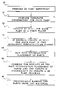
FIG. 7 is a flow chart illustrating the steps of the method of part removal in
accordance with the present invention.
DETAILED DESCRIPTION OF THE PREFERRED EMBODIMENTS
Referring to FIG. 7, a method of removal of 3D parts from a material is shown
in flow chart fashion according to the present invention.

2180412
- 4 -
A standard CAD/NC software module is used to define the three dimensional
geometry of the workpiece in step 10. This definition includes information
such as
any required orientation of the part with respect to the material, such as
fiber
direction, etc. The NC part of the module allows the definition of the
toolpath in step
12 (cutter location) considering all possible available tools such as
ultrasonic knives
14 (FIG. 2) of different shapes (disk knives, triangular shaped blades, etc.
and milling
tools 16 (FIG. 3) like, but not limited to, end milling cutters or spherical
cutters. The
result of that procedure is stored for every single part in a separate file
(usually an
APT or CLDATA file).
The ultrasonic cutters 14 or milling cutters 16 are tools which can be used in
an ultrasonic cutting machine 18 (FIG. 1) which has at least three axes of
movement
and preferably has five or six axes about which movement can occur, including
movement of the cutting device relative to material 20, which is carried on a
bed 22
of the machine, along the X axis, the Y axis and the Z axis. Other axes are
provided
in order to allow for angled cutting of parts from the material 20. The next
process
after defining the tool paths in step 12 is "2D mapping" which occurs in step
30
(FIG. 7). Two dimensional mapping takes the 3D geometry information and
creates a
two dimensional shape or contour, defined as the base of the general prism or
cylinder of material, minimal in size, which is necessary to finish that part.
Material
outside that solid is not necessary and will not be touched or hurt during the
part
processing. This two dimensional shape must completely include the projection
of
the three dimensional part onto the X/Y plane or generally the support plane,
such as
the machine bed 22. The shape will be bigger at locations where additional
material
has to be removed during part processing to create complicated surfaces. Two
dimensional mapping must keep track of the reference point (start position of

2180412
- 5 -
machine movements in reference to the origin of the X/Y plane). The result of
the
2D mapping process of step 30 is stored in geometry files in whatever format
can be
processed by the nesting system (e.g. DXF, IGES files).
For example, FIG. 4 illustrates a three dimensional part 40 which has a small
rectangular top surface 42 and a large rectangular bottom surface 44 with
sloping
planar sidewalls 46. FIG. 5 illustrates a 2D mapping of this part on to the
X/Y plane.
It is seen that an outer contour 48 is sized slightly larger than the bottom
surface 44
in order to allow for some minimal wastage resulting from the cutting
operation. In
this arrangement, it is assumed that regular rectangular blocks are first cut
from the
material with the largest X and Y dimensions corresponding to the largest X
and Y
dimensions of the part 40.
In step 60 (FIG. 7) a nesting optimization is performed which results in the
placement of product patterns in the material 20 so as to optimize usage of
the
material and to minimize any waste material. This is shown in FIG. 5 in that
the
rectangular blocks 48 are abutted one to the next so as to leave no spacing in
between adjacent blocks.
Step 62 provides an optional procedure whereby even greater material savings
can be attained. In this further step a two dimensional hull or contour for
each part
is created for the remaining two perpendicular planes, that is, the X/Z and
Y/Z
planes. This information is then used in step 60 to permit a nesting to occur
in all
three planes so as to take advantage of 3D contours of the articles to achieve
a
greater material savings.
For example, FIG. 6 shows an optimized mapping of the part 40 of FIG. 4 in
which alternating patterns are rotated 180° around the X axis in order
to take
advantage of the complementary sloping surfaces to further minimize waste
material.

2~804i2
- 6 -
This arrangement, of course, assumes that the characteristics of the material
and of
the resulting part permit this rotation or inversion of the part, however,
this
information is part of the information contained in the original definition of
the three
dimensional part as prepared in step 10.
The results of the nesting optimization placement of parts from step 60 and
the tool path information from step 12 is combined in step 66 to create a 3D
part
program which then can be loaded onto the numerically controlled machine 18
for
the part removal. The program includes tool selection information as well as
cutting
information. The result is that as the machine 18 is operated, all of the
parts
requested are processed and removed from the material (step 68) without
damaging
the material to be used for other parts, an overall material utilization is
optimized.
As is apparent from the foregoing specification, the invention is susceptible
of
being embodied with various alterations and modifications which may differ
particularly from those that have been described in the preceding
specification and
description. It should be understood that I wish to embody within the scope of
the
patent warranted hereon all such modifications as reasonably and properly come
within the scope of my contribution to the art.

Representative Drawing
A single figure which represents the drawing illustrating the invention.
Administrative Status

2024-08-01:As part of the Next Generation Patents (NGP) transition, the Canadian Patents Database (CPD) now contains a more detailed Event History, which replicates the Event Log of our new back-office solution.

Please note that "Inactive:" events refers to events no longer in use in our new back-office solution.

For a clearer understanding of the status of the application/patent presented on this page, the site Disclaimer , as well as the definitions for Patent , Event History , Maintenance Fee  and Payment History  should be consulted.

Event History

Description Date
Time Limit for Reversal Expired 2008-07-03
Letter Sent 2007-07-03
Inactive: IPC from MCD 2006-03-12
Grant by Issuance 2005-03-29
Inactive: Cover page published 2005-03-28
Inactive: Final fee received 2005-01-12
Pre-grant 2005-01-12
Notice of Allowance is Issued 2004-09-03
Letter Sent 2004-09-03
Inactive: Approved for allowance (AFA) 2004-08-23
Amendment Received - Voluntary Amendment 2003-05-02
Amendment Received - Voluntary Amendment 2002-10-15
Inactive: Application prosecuted on TS as of Log entry date 2002-09-09
Letter Sent 2002-09-09
Inactive: Status info is complete as of Log entry date 2002-09-09
Request for Examination Requirements Determined Compliant 2002-08-15
All Requirements for Examination Determined Compliant 2002-08-15
Application Published (Open to Public Inspection) 1997-01-18

Abandonment History

There is no abandonment history.

Maintenance Fee

The last payment was received on 2004-06-07

Note : If the full payment has not been received on or before the date indicated, a further fee may be required which may be one of the following

  • the reinstatement fee;
  • the late payment fee; or
  • additional fee to reverse deemed expiry.

Patent fees are adjusted on the 1st of January every year. The amounts above are the current amounts if received by December 31 of the current year.
Please refer to the CIPO Patent Fees web page to see all current fee amounts.

Fee History

Fee Type Anniversary Year Due Date Paid Date
MF (application, 2nd anniv.) - standard 02 1998-07-03 1998-06-18
MF (application, 3rd anniv.) - standard 03 1999-07-05 1999-06-10
MF (application, 4th anniv.) - standard 04 2000-07-03 2000-06-19
MF (application, 5th anniv.) - standard 05 2001-07-03 2001-03-08
MF (application, 6th anniv.) - standard 06 2002-07-03 2002-04-30
Request for examination - standard 2002-08-15
MF (application, 7th anniv.) - standard 07 2003-07-03 2003-06-03
MF (application, 8th anniv.) - standard 08 2004-07-05 2004-06-07
Final fee - standard 2005-01-12
MF (patent, 9th anniv.) - standard 2005-07-04 2005-06-02
MF (patent, 10th anniv.) - standard 2006-07-03 2006-06-06
Owners on Record

Note: Records showing the ownership history in alphabetical order.

Current Owners on Record
AMERICAN GFM CORPORATION
Past Owners on Record
ERICH ALEXANDER ZARZER
GERHARD MARXRIESER
Past Owners that do not appear in the "Owners on Record" listing will appear in other documentation within the application.
Documents

To view selected files, please enter reCAPTCHA code :


To view images, click a link in the Document Description column. To download the documents, select one or more checkboxes in the first column and then click the "Download Selected in PDF format (Zip Archive)" or the "Download Selected as Single PDF" button.

List of published and non-published patent-specific documents on the CPD .

If you have any difficulty accessing content, you can call the Client Service Centre at 1-866-997-1936 or send them an e-mail at CIPO Client Service Centre.


Document
Description 
Date
(yyyy-mm-dd) 
Number of pages   Size of Image (KB) 
Representative drawing 1997-08-20 1 11
Claims 2003-05-01 4 104
Drawings 1996-10-27 4 103
Abstract 1996-07-02 1 12
Claims 1996-07-02 4 95
Description 1996-07-02 6 230
Drawings 1996-07-02 7 132
Representative drawing 2004-08-16 1 13
Reminder of maintenance fee due 1998-03-03 1 111
Acknowledgement of Request for Examination 2002-09-08 1 177
Commissioner's Notice - Application Found Allowable 2004-09-02 1 160
Maintenance Fee Notice 2007-08-13 1 172
Correspondence 1996-10-27 8 210
Fees 2003-06-02 1 30
Fees 2001-03-07 1 29
Fees 2002-04-29 1 36
Fees 1998-06-17 1 33
Fees 1999-06-09 1 29
Fees 2000-06-18 1 26
Fees 2004-06-06 1 31
Correspondence 2005-01-11 1 35
Fees 2005-06-01 1 31
Fees 2006-06-05 1 31