Language selection

Search

Patent 2180696 Summary

Third-party information liability

Some of the information on this Web page has been provided by external sources. The Government of Canada is not responsible for the accuracy, reliability or currency of the information supplied by external sources. Users wishing to rely upon this information should consult directly with the source of the information. Content provided by external sources is not subject to official languages, privacy and accessibility requirements.

Claims and Abstract availability

Any discrepancies in the text and image of the Claims and Abstract are due to differing posting times. Text of the Claims and Abstract are posted:

  • At the time the application is open to public inspection;
  • At the time of issue of the patent (grant).
(12) Patent: (11) CA 2180696
(54) English Title: RESIN TRANSFER MOLDING APPARATUS AND METHOD OF FABRICATION THEREOF
(54) French Title: DISPOSITIF DE MOULAGE PAR TRANSFERT DE RESINE ET PROCEDE DE FABRICATION
Status: Term Expired - Post Grant Beyond Limit
Bibliographic Data
(51) International Patent Classification (IPC):
  • B29C 45/02 (2006.01)
  • B29C 33/38 (2006.01)
  • B29C 33/40 (2006.01)
  • B29C 43/36 (2006.01)
  • B29C 70/48 (2006.01)
(72) Inventors :
  • YAKEL, DALE S. (United States of America)
(73) Owners :
  • OUTBOARD MARINE CORPORATION
(71) Applicants :
  • OUTBOARD MARINE CORPORATION (United States of America)
(74) Agent: SMART & BIGGAR LP
(74) Associate agent:
(45) Issued: 2007-09-04
(22) Filed Date: 1996-07-08
(41) Open to Public Inspection: 1997-03-12
Examination requested: 2003-03-12
Availability of licence: N/A
Dedicated to the Public: N/A
(25) Language of filing: English

Patent Cooperation Treaty (PCT): No

(30) Application Priority Data:
Application No. Country/Territory Date
08/526,568 (United States of America) 1995-09-11

Abstracts

English Abstract

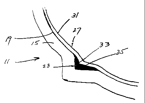
Disclosed herein is a resin transfer molding apparatus comprising a female mold member including a rigid surface including a recessed area, and a male mold member including a flexible bag which is adapted to be drawn into close association with said rigid surface of said female mold member in response to the application of vacuum therebetween and which includes an area of increased thickness which has a shape conforming to said recessed area in said rigid surface of said female mold member.


French Abstract

Cette invention concerne un appareil de moulage par transfert de résine comprenant un élément de moule femelle incluant une surface rigide munie d'une zone évidée, et un élément de moule mâle incluant un sac flexible qui est adapté pour être attiré en association étroite avec ladite surface rigide dudit élément de moule femelle en réponse à l'application de vide entre eux et qui inclut une zone d'épaisseur accrue ayant une forme épousant ladite zone évidée dans ladite surface rigide dudit élément de moule femelle.

Claims

Note: Claims are shown in the official language in which they were submitted.


8
CLAIMS:
1. A resin transfer molding apparatus comprising a
female mold member including a rigid surface including a
main surface portion, and a recessed surface portion
extending inwardly from and bordered by said main portion to
define a recessed area, and a male mold member including a
structure which is adapted to be drawn into close
association with said rigid surface of said female mold
member in response to the application of vacuum therebetween
and which includes a member which is at least partially
flexible and which includes an inner surface located, during
the application of vacuum, in relatively adjacent opposing
relation to said main surface portion of said female mold
member and in relatively spaced relation to said recessed
surface portion, and a segment which is relatively rigid,
which has a shape conforming to said recessed area, which is
fixedly bonded to said inside surface of said member, and
which is located, during the application of vacuum, in
relatively adjacent opposing relation to said recessed
surface portion of said female mold member.
2. A resin transfer molding apparatus in accordance
with claim 1 wherein said member is a flexible bag
fabricated of silicone, and wherein said segment is
fabricated from a two-part silicone mixture.
3. A resin transfer molding apparatus in accordance
with claim 1 wherein said member is semi-flexible, and
wherein said segment is fabricated from a two-part silicone
mixture.

Description

Note: Descriptions are shown in the official language in which they were submitted.


CA 02180696 2005-10-12
62396-1031
1
RESIN TRANSFER MOLDING APPARATUS
AND METHOD OF FABRICATION THEREOF
BACKGROUND OF THE INVENTION
The invention relates generally to resin transfer
molding and, more particularly, to molding apparatus for
such resin transfer molding. The invention also relates
more particularly to methods of fabricating resin transfer
molding apparatus.
In the past, when a female mold member included a
recess which was sufficiently small or sharp, the flexible
bag was sometimes unable to enter into the recess in close
association with the recess and, as a consequence, in molded
articles including such a recess, the article included
excessive amounts of the resin in the recessed area. One
example of such a recess which produced excessive amounts of
resin in the molded article is the recess which produces a
chine or strake on the outer surface of a boat hull.
Such articles with excessive amounts of resin were
not as economically manufactured as they might be.
Attention is directed to U.S. Patent 4,822,436
(issued April 18, 1989), as well as PCT Application
WO 85/01472 (International Publication date: 11 April 1985)
and German Application 34 39 285 (Issued 22 August 1985).
SUMMARY OF THE INVENTION
The invention provides a resin transfer molding
apparatus comprising a female mold member including a rigid
surface including a main surface portion, and a recessed

CA 02180696 2005-10-12
62396-1031
2
surface portion extending inwardly from and bordered by said
main portion to define a recessed area, and a male mold
member including a structure which is adapted to be drawn
into close association with said rigid surface of said
female mold member in response to the application of vacuum
therebetween and which includes a member which is at least
partially flexible and which includes an inner surface
located, during the application of vacuum, in relatively
adjacent opposing relation to said main surface portion of
said female mold member and in relatively spaced relation to
said recessed surface portion, and a segment which is
relatively rigid, which has a shape conforming to said
recessed area, which is fixedly bonded to said inside
surface of said member, and which is located, during the
application of vacuum, in relatively adjacent opposing
relation to said recessed surface portion of said female
mold member.
Other features and advantages of the invention
will become apparent to those skilled in the art upon review
of the following detailed description, claims and drawings.
DESCRIPTION OF THE DRAWINGS
Figure 1 is a fragmentary sectional view of a
resin transfer molding apparatus in accordance with one
embodiment of the invention.
Before one embodiment of the invention is
explained in detail, it is to be understood that the
invention is not limited in its application to the details
of the construction and the arrangements of components set
forth in the following description or illustrated in the
drawings. The invention is capable of other embodiments and
of being practiced or being carried out in various ways.

CA 02180696 2005-10-12
62396-1031
3
Also, it is understood that the phraseology and terminology
used herein is for the purpose of description and should not
be regarded as limiting.
DESCRIPTION OF THE PREFERRED EMBODIMENT
Shown in the drawings is a resin transfer molding
apparatus 11 comprising a female mold member 15 including a
rigid surface 19 including a recess or recessed area 23, and
a male mold member 27 including a structure or bag 31 which
can be flexible or semi-rigid and which is adapted to be
drawn into close association with the rigid surface 19 of
the female mold member 15 in response to the application of
vacuum therebetween and which includes an area of increased
thickness or an enlargement 35 which has a shape conforming
to the shape of the recess or recessed area 23 in the rigid
surface 19 of the female mold member 15.
While many other applications exist, in the
disclosed construction, the molding apparatus 11 is adapted
for molding a boat hull (not fully shown) including a chine
or strake which extends for a substantial length along the
boat hull and which, in general, projects outwardly from the
general lines of the boat hull. As a consequence, the
recess 23 in the female mold member 15 is in the shape of a
chine and is defined by surfaces which define a relatively
sharp recess. Any suitable female mold member construction
can be employed.
The structure or bag 31 can be constructed in any
suitable manner, can, as already noted, be either flexible
or semi-rigid, i.e., partially flexible, and, while other
constructions can be employed, in the disclosed
construction, the stricture or bag 31 is a relatively thin
walled and generally flexible bag constructed of silicone.

CA 02180696 2005-10-12
62396-1031
4
The bag 31 can include a dart or other projecting shape 33
which extends partially into the recess 23 in spaced
relation to the surfaces thereof. If desired, the bag 31
can curvilinearly extend past the recess 23 without
partially extending thereinto.
The enlargement(s) or increased thickness area(s)
35 can be fabricated of various filler materials and in the
disclosed construction, the increased thickness area 35 is
fabricated of a curable material which, when cured, is
rigid, and is fixedly bonded to the flexible bag. While
other materials can be employed, in the disclosed
construction, the area 35 of increased

2180696
-5-
thickness is preferably fabricated from a curable
plastic material, such as a two-part silicone mixture
consisting of a resin and a hardener. Any suitable
two-part silicone mixture can be employed.
The resin transfer molding apparatus 11 is
fabricated by a method including the steps of
fabricating the female mold member 15 including the
rigid surface 19 having therein the recessed area 23,
applying a releasing agent to at least the recessed
area 23 of the rigid surface 19 of the female mold
member 15, filling the recessed area 23 with a filler
material, locating a structure which can be in the form
of a flexible bag 31 in close association with the
rigid surface 19 of the female mold member 15 and with
the filler material in the recessed area 23, and
solidifying the material in the recessed area 23 and
adhering the material to the flexible bag 31.
Any suitable releasing agent capable of preventing
adhesion of the curable plastic material to the rigid
surface 19 of the female mold member 15 can be
employed. In the preferred construction, the releasing
agent is applied to the entire surface 19 of the female
mold member 15.
The step of filling the recessed area 23 with
filler material can be performed in any suitable
manner.
In one embodiment of the invention, the locating
step includes the step of placing the flexible bag 31
adjacent the rigid surface 19 of the female mold member
15 and the filler material, sealing the perimeter of
the bag 31 to the female mold member, and drawing and
maintaining a vacuum between the flexible bag 31 and
the rigid surface 19 of the female mold member 15 so as
to locate the flexible bag 31 in generally evenly

2180696
-6-
spaced relation to, and close association with, the
rigid surface 19 of the female mold member 15 and in
contact with the filler material.
The steps of placing the flexible bag 31 in the
female mold member 15 and sealing the flexible bag 31
to the female mold member 15, thereby to facilitate
drawing a vacuum between the flexible bag 31 and the
female mold member 15, can be accomplished in any
suitable manner.
Any suitable arrangement can be employed for
drawing or creating and maintaining a vacuum between
the female mold member 15 and the flexible bag 31.
In one embodiment of the invention, the filler
material is preferably a curable plastic material, such
as a two-part silicone plastic, and any suitable
arrangement can be employed for curing or solidifying
the plastic material and for effectively bonding or
adhering the plastic material to the flexible bag 31.
The curing step is completed during maintenance of the
vacuum, i.e., before termination of the vacuum.
When employing the resulting resin transfer
molding apparatus 11 in the molding of an article, such
as a boat hull, upon the application of vacuum, the
enlargement or increased thickness area 35 of the
flexible bag 31 extends into the recess 23 in close
association to the rigid surface 19 of the female mold
member 15 and prevents accumulation of excessive
amounts of resin in the recess. The method is
particularly applicable to the resin transfer molding
of boat hulls provided with chines and/or strakes.
Because the enlargement or area of_increased thickness
is fabricated in the recess 23 of the female mold
member 15, the enlargement or increased thickness area

2180696
-7-
35 has the shape of the recess 23 which, in the case of
the disclosed boat hull, is the shape of a chine.
Various of the features are set forth in the
following claims.

Representative Drawing
A single figure which represents the drawing illustrating the invention.
Administrative Status

2024-08-01:As part of the Next Generation Patents (NGP) transition, the Canadian Patents Database (CPD) now contains a more detailed Event History, which replicates the Event Log of our new back-office solution.

Please note that "Inactive:" events refers to events no longer in use in our new back-office solution.

For a clearer understanding of the status of the application/patent presented on this page, the site Disclaimer , as well as the definitions for Patent , Event History , Maintenance Fee  and Payment History  should be consulted.

Event History

Description Date
Inactive: Expired (new Act pat) 2016-07-08
Inactive: Late MF processed 2011-07-26
Inactive: Office letter 2011-07-13
Letter Sent 2011-07-08
Inactive: Late MF processed 2011-06-22
Letter Sent 2010-07-08
Grant by Issuance 2007-09-04
Inactive: Cover page published 2007-09-03
Inactive: Final fee received 2007-05-14
Pre-grant 2007-05-14
Notice of Allowance is Issued 2006-11-15
Letter Sent 2006-11-15
Notice of Allowance is Issued 2006-11-15
Inactive: Approved for allowance (AFA) 2006-11-01
Inactive: IPC from MCD 2006-03-12
Amendment Received - Voluntary Amendment 2005-10-12
Inactive: S.30(2) Rules - Examiner requisition 2005-04-25
Inactive: Application prosecuted on TS as of Log entry date 2003-04-08
Letter Sent 2003-04-08
Inactive: Status info is complete as of Log entry date 2003-04-08
All Requirements for Examination Determined Compliant 2003-03-12
Request for Examination Requirements Determined Compliant 2003-03-12
Letter Sent 2002-06-17
Reinstatement Requirements Deemed Compliant for All Abandonment Reasons 2002-05-29
Deemed Abandoned - Failure to Respond to Maintenance Fee Notice 2001-07-09
Inactive: Cover page published 2000-12-21
Application Published (Open to Public Inspection) 1997-03-12

Abandonment History

Abandonment Date Reason Reinstatement Date
2001-07-09

Maintenance Fee

The last payment was received on 2007-06-19

Note : If the full payment has not been received on or before the date indicated, a further fee may be required which may be one of the following

  • the reinstatement fee;
  • the late payment fee; or
  • additional fee to reverse deemed expiry.

Patent fees are adjusted on the 1st of January every year. The amounts above are the current amounts if received by December 31 of the current year.
Please refer to the CIPO Patent Fees web page to see all current fee amounts.

Owners on Record

Note: Records showing the ownership history in alphabetical order.

Current Owners on Record
OUTBOARD MARINE CORPORATION
Past Owners on Record
DALE S. YAKEL
Past Owners that do not appear in the "Owners on Record" listing will appear in other documentation within the application.
Documents

To view selected files, please enter reCAPTCHA code :


To view images, click a link in the Document Description column. To download the documents, select one or more checkboxes in the first column and then click the "Download Selected in PDF format (Zip Archive)" or the "Download Selected as Single PDF" button.

List of published and non-published patent-specific documents on the CPD .

If you have any difficulty accessing content, you can call the Client Service Centre at 1-866-997-1936 or send them an e-mail at CIPO Client Service Centre.


Document
Description 
Date
(yyyy-mm-dd) 
Number of pages   Size of Image (KB) 
Representative drawing 1997-08-20 1 6
Representative drawing 2000-12-10 1 6
Drawings 1996-07-07 1 9
Description 1996-07-07 7 249
Abstract 1996-07-07 1 15
Claims 1996-07-07 4 110
Claims 2005-10-11 1 38
Description 2005-10-11 7 226
Representative drawing 2007-08-02 1 6
Drawings 2007-09-02 1 9
Abstract 2007-09-02 1 15
Description 2007-09-02 7 226
Reminder of maintenance fee due 1998-03-09 1 111
Courtesy - Abandonment Letter (Maintenance Fee) 2001-08-05 1 182
Notice of Reinstatement 2002-06-16 1 172
Reminder - Request for Examination 2003-03-10 1 120
Acknowledgement of Request for Examination 2003-04-07 1 185
Commissioner's Notice - Application Found Allowable 2006-11-14 1 163
Maintenance Fee Notice 2010-08-18 1 170
Late Payment Acknowledgement 2011-07-11 1 164
Late Payment Acknowledgement 2011-08-07 1 163
Maintenance Fee Notice 2011-08-07 1 170
Late Payment Acknowledgement 2011-08-07 1 163
Fees 2002-05-28 2 80
Fees 2001-06-12 1 32
Correspondence 2007-05-13 1 39
Correspondence 2011-07-12 1 22