Note: Descriptions are shown in the official language in which they were submitted.
- -
~ WO95/l9576 21 807 ~9 r~ 4
Meth~d and A~ ratl~c for Position;ng Conqtruction M~oh-n~ry
This invefftion relates to a method of positioning
construction r~-h; n;~ry on the site of civil engineering or
construction works (including offshore construction works), and
5 more ~Rrer; ~l l y (though not exclusively) positioning rigs for
the inst~ t;~n or formation of piles or other foundation
works . It; nf l ll~l/'Q apparatus for operation of the method and
piling rigs and other construction - -~h; n~ry in which 8uch
apparatus is in8talled.
In current practice, such r-t hin~ry is positioned for
operation by sighting with standard surveying instrume~ts with
reference to pegs or other markers laid out on the site before
work commences. This established te~hn;s~P is well able to
provide the required positioning accuracy, but it is liable to
15 require skilled surveyors on site for only occasional activity,
expensive delays are liable to arise when markers are
ac~irlont~lly knocked over or ~;CplAC~ (not a rare event on
sites where heavy construcion ~~rh;n~ry is moving about) and
even more expensive mistakes may arise if the markers are
20 misinterpreted - for instance some surveyors will locate
markers on the centre-line of a row of piles while others
prefer to align them with a face of the piles - or if
ar~ nt~l ~; Qrl ~ ' goes unnoticed.
In the r--nt;~~, navigational sytems based on the use of
25 satellites and in particular the Navstar Global Positioning
5ystem or GPS have been developed to the point at which their
precision can achieve about ~5mm, except for short periods when
the position of the system satellites is unfavourable.
Xowever, it is dif f icult and not always practicable to operate
30 a GPS system with its antenna at ground level on a construction
site, where the presence of large metallic bodies (such as the --
constructio~ machinery itself and in some cases the metal
WO 95119576 ~ 7 2 ~ 2 r~
frames of adjoining buildings) may attenuate the satellite
signals to the point at which they cannot be detected, or worse
may def lect them and give systematic errors in the GPS
measurement. Deep fo~ln~l~tir~n construction equipment (such as
5 pile rig6 and diap~lragm wall rigs) and other like ~-rh;n~c are
normally tall enough for reliable readings to be taken with a
GPS antenna at the top of the machine, but this only
substitutes the problem of relating the position of the antenna
to that of the working part of the machine at ground level,
10 which may vary by up to a metre or 80 for instance as the
machine follows the imperfect contour of the site surface,
deflects in the wind, and/or vibrates.
In accorda~Lce with the present invention, a method of
positioning a con8truction machine on a work site comprises
(a) providing the said machine with a mast having a
r in~l ly vertical axis passing through a point (herein
considered the centre of operation of the machine) at ground
level which it is desired to bring to predetermined locations;
(b) providing a satellite navigation system receiver
having an antenna located on the said axis at the top of the
mast;
(c) providing means for ~.t~rm;n;n~ the ~;crl~r t of
the mast from its nominal vertical position;
(d) obtaining output readings from the said navigation
system receiver when the said displ ~l is less than a
predetermined limit and distinguishing these said output
readings from any other output readings that may be obtained
when the said displacement is not less than the said
predetermined limit; and
(e) positioning the machine in response to these said
output readings.
In mot case th~ n~ ;n~l ly vertical mast will be an
WO 95/19576 2 ~ 8 0 7 2 9 r~ "ss ~ ~
intrinsic part of the machine, though a minor extension may be
needed for positioning the antenna accurately on the axis.
The navigation system is preferably one of the
high-precision GPS receivers, such as those marketed or under
5 development by Trimble Navigation Inc having its principal
place of business at 645 Mary Avenue, Sunnyvale CA 94068, USA
and a subsidiary Trim.ble Navigation (Europe~ Ltd at Osborn Way,
Hook, T~Amr~h; re ~herein together called Trimble) . More
especially, we re~: ' receivers which operate using the L1
10 and ~2 P-code and carrier when available and using L1 C~ code
and cross-correlation of the encrypted Y-code when the L1 and
L2 signals are scrambled. At present we prefer to use
receivers of Trimble's '~4000'~ series with Allt- t;C
ini~;AliqAt;~ on th fly, and most eqpPriAlly model 4000SSE.
WOg3/05588 is thought to describe some features of such
receivers .
The receiver may be provided with any appropriate
conventional interpretation software, and in particular
preferably with software for gene~~ting an output representing
20 displacement from a target position entered manually or from a
C~D f ile representing the design of the works to be executed .
It may be desirable, if the - v q. of the mast are
appreciable within the normal sampling period of the receiver
(usually 1 or 2 seconds) to modify the software to sample at
25 variable intervals when the mast is found to be sufficiently
close to vertical.
Various kinds of tiltmeter (also called an ;nr-l ;n~-cter
or ~l ;nr~m~tl~r) are available and can be uged to (li~t~rm;n,~
displacements of the mast f rom the vertical . The requirements
30 are for a response time o~ a fraction of a second or better and
an accuracy of the order of 1 in 2500 or 40 seconds of arc (to
support an accuracy of ~ ~ Omm when the mast is 2~m high) . At
w
o 95/19576 2 ~ ~ C 7 2 9 r~
.
present we prefer tiltmeters based on self-levelling of fluids
with appropriate viscosity to damp osr;ll~t;nnq and more
~sp.or; ;111 y "electr~nic" tiltmeters in which v~ t of the
self-levelling fluid affects the capacitance between plates of
5 a capacitor, so that no solid moving parts are needed Good
results have geen obtained with the tiltmeters sold by Monitran
I,td of 33 Hazlemere Road, Penn, B~lrk;n~h~ h;~e, GB under the
designation AccuStar Electronic Clinometer.
If the mast cannot be set stably vertical to the reguired
10 tolerance and random ~, t~ of the mast do not provide an
adequately short s ,1; n~ period, means may be provided to
introduce oscillatory, v~ ts (around one or two axes close
to ground level) to ensure that the mast will be frequently
vertical .
There is no necessity to obtain any output readings from
the navigation system receiver when the mast is not vertical
within the chosen tolerance, but it is convenient to do 80
provided that such readings are distinguished (for example by
displaying them at reduced intensity or in a different colour
20 from output signals obtained when it is vertical within the
chosen tolerance) and are not relied on for positioning the
~^^h; n~ry for operation.
The predetermined limit below which the displ ~ - t of
the mast from vertical must be before output readings are used
25 may be a constant predet~t~n;n-~d angle. We prefer, however,
that the limit is reduced as the machine approaches its target
position. The limit might be a cnnt;n~l ly changing function;
for instance it might be tan 1 (r/5h), where r i8 the most
recently indicated distance from target and h the height of the
30 mast (or a step function apprr~;r-t;n~ it more or less
closely), so that the error due to deviation of the mast from
vertical would be limited to half an order o~ magnitude less
~ W0 95/19576 2 ~ 8 0 7 2 9 r~ ," '~
than the current displAr^-^nt of the machine from its target
position. We find it more practical, however, that the limit
changes in a small number of large steps and the display of the
output changes cuLLe~undingly, 80 that pos~-ioning comprises a
short sequence of adj u i ~ of increasing precision . The
number and size of the steps can be chosen to suit the
conditions of a particular site, if desired.
The machine may be positioned in response to the output
signals by a human driver, or in suitable cases the output
signals may be input into a computer control sy8tem to allow
the machine to seek it8 in8tructed position automatically.
~RpPr;A11y in the latter cage, final adjustment may be made by
moving the mast with respect to the bage of the InArh; nf~ry,
rat~er than by moving the base of the --rh;n~ry along the
ground.
The i~vention will be further described, by way of
example, with reference to the A' , ~ing drawings in which:
Firl~re 1 is a diagrammatic view of a piling rig eriuipped with
apparatus in accordance with the invention, and
Fiç~ureR 2-7 show one way in which output mea~ tq may be
presented to a human driver as a succession of ~screens~ in a
computer display in his cab.
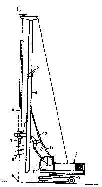
For purpose of illustration, the rig shown in Figure 1 is
an auger piling rig for making one kind of cast-in-situ
concrete foundation pile. The rig comprigeg a body 1 (;nrll~rl;
a driver ~ 8 cab 2 ) rotatably mounted on a tracked base 3, which
can be driven relatively precisely in a f orward and rearward
direction and can be steered, with rather less precision, by
dif ferer,tially driving its two tracks in the usual way.
On the front of the body is mounted a mast 5 supporting
an auger 6 with appropriate drive gear 7, the rotation axi8 8
of which defines the nr~;nA~ly vertical axis of the mast; the
Wo 95~19576 2 t ~ ~ 7 2 ~
intersection 9 of this axis with the ground determines the
centre of operation of the machine, where the auger will enter
the ground and the pile will be formed. The problem is to
locate the point 9 on the ground with suf f icient accuracy,
5 notwithstanding that the surface on which the rig stands may
not be horizontal to the required accuracy, the hydraulic
~ ~n j e~m 10 holdi ng the mast upright may not be set at the
optimum angle, the wind may cause the mast to def lect and/or
~5~;11 ;~te significantly and in some cases (mostly when the mast
10 is already out of vertical for one of the other reasons) the
mast may bend.
In accordance with the invention, the rig is provided
with a GPS receiver and the antenna 11 of that receiver is
located at the top of the mast 5, while at least the output
15 display ~Figures 2-7) is in the cab 2. A pair of electronic
tiltmeters 12 (gay of AccuStar electronic ~ t~rs) is also
f itted to the mast 5 and provides signals ~ cs~Ling the
displ ~ of the axis 8 f rom a truly vertical position in
mutually perpendiculat directions - preferably on the pitch and
20 roll axes relative to the body of the machine. (At some stages
of operation, this signal will also be displayed to the driver
to assist adjusting the mast to a vertical position). A vector
signal ~using this expression in a broad sense to include, for
example, a pair of error signals with + or - signs) is
25 preferable as giving an; ';~te indication of corrective
action to be taken for vertical setting of the mast.
In the particular system illustrated by Figures 2-7, the
driver~s display initially shows (Figure 2) a listing 13 of the
piles to be insta].led, with their intended location co-
30 ordinates (Eastings and Northings, for instance in accordancewith the United Kingdom Ordnance Survey's ~;lt;t~n;ll Grid) which
~as previously b~en downloaded, say from a floppy disk produced
~ WO 95/19576 2 1 ~ ~ 7 2 9 F~ .,,,5 0~l C4
by the de8ign of f ice computer . Contract and status
information 14 may also be displayed. The operator selects a
pile to be installed first, say by highlighting it in the list
and pressing a function key or an enter key, and the display
5 changes to show (Figure 3 ) a site plan 15 with the intended
position of the selected pile (the target position) 16 and the
position of the piling rig as indicated by the GPS system (the
indicated position) 17: at this stage it does not matter if the
mast is out of vertical and the; n~l; c~Ated position of the rig
10 conse~uently inaccurate. The operator drives the rig towards
the target position, and will have no difficulty in coming
within a few metres of iti if desired, the track of the rig
across the site can be displayed as a "snail trail" on the
display. When the distance between the target position and the
15 indicated position is less than lOm (say), the display changes
scale (as seen in Figure 4) to facilitate the next step of
adjusting the position to within 2m (say) by driving the rig
backwards or forwards, steering if nPcPCCAry~ and rotating the
rig around its own n~ nA l l y vertical rotation axis to make
20 sideways adjustments within the range that the 1l; c; ~nc of
the rig allow.
At this stage t~e display changes again, to the form
shown in Figure 5 comprising a bullseye display 18 showing the
target position 16 with ron~ Pnt~ic circles 19-22 around it,
25 along with the ;n~ tPd position 17, and a tilt display 23
displaying the outputs of the tiltmeters as left-right and
forward-back tilt indications 24, 25 respectively on a '~cross-
hair" diagram; the scale of each of these parts of the display
will change progressively as the target position is approached.
30 At this stage, the outer circle of the bullseye display
corresponds to 2m on the ground and the scale of the tilt
dis~lay 23 is such that the central space 26 between the ~ixed
W0 95119576 2 ~: 8 7 ~ q 8 F~~
rectangles correspond6 to a tilt range of ~15 ' of arc ~hen
the difference between the indicated position and the target
position falls below lm, the scale of the bullseye display
changes 80 that the outer circle represents lm, for greater
precision of positioning; on a colour display, it may a~so
change colour to ~ive a conspicuous ;n~i;r~tinn of the change.
When the difference between the ;nrl;r~tPtl~position and the
target position falls below 0.5m for the first time, the scale
of the display (a~d its colour, if desired) changes again 80
that the outer circle now represents 0 . 5m, and at the same time
the sof tware imposes an angular tolerance on the tilt equal to
il5 ~; usually this tolerance will not be met, in which ca~e the
bullseye display is dimmed (on a monochrome screen) or set to
grey (on a colour screen~ to indicate that the mast is not
sufficiently vertical for the ;nrl;r~t~ position to be
accurate, and the operator next adjusts the mast using the
standard ~r~ of the rig until the two tilt ;nrl;r:~tl~nq
are brought within the central space 26 of the crosshair
display or (if th~ mast is swaying) are nBr; 11 ct;n~ across it .
In the latter case, the GPS output signal is suppressed except
when the tilt is within this tolerance, and in any case the
display brightens (on a monochrome screen) or becomes coloured
to indicate that the bullseye display is now accurate enough to
be useful. The driver adjusts position accordingly, pausing to
re-adjust the mast if dimming (or 1088 of colour) ;ntl;r~t~R
that it is nPrPcg~ry When (with the mast vertical wit~in the
il5 ' angular tolerance) the distance between the target
position and the indicated position falls below 0.25m, the
angular tolerance is reduced to 6 ~ and the crosshair display
changes scale 80 that the central space 26 now represents 6 ~ of
arc. Adjustment rnnt;nlloc as before to this new accuracy, and
when the difference between the ta get position and the
wo95/19576 P~~ S_'C~~'~
2~$~7~9
indicated position falls below O.lm, a similar and final change
occurs so that the angular tolerance i8 0~30" of arc and the
scale of the crosshair display corresponds to it; the bullseye
~nnt;nllPs to dim or lose colour, as the case may be, if the
5 mast is not vertical within the tolerance set for the time
being and the operator continues to respond to this, when
n~C~cc~ry, by adjusting the mast. (The example figures in this
paragraph are appropriate for a good quality site; on an uneven
site, angular tolerances may need to be set gisn; f; -~ntly
10 sooner) .
When, with the maximum scale and lowest tolerances, the
distance between the target position and the; n~ t~d position
remains below lOmm for a sufficient time to indicate that the
rig is stationary Isay 1-2 seconds, or 1024ms may be convenient
15 to some software), a READY message 27 (Figure 6) is displayed,
which the operator acknowledges with a function key, and pile
inst~ t;nn can begin. The display may change again
~Figure 7) to display a PIr,ING IN PROGRESS message 28 ~hile the
GPS system Cnn~; n~ to record position (which may change
20 slightly while the pile is being installed). Appropriate
instrumentation may be added to allow the depth achived to be
displayed as well, if desired. Further operation of a function
key signals, , ~ n of piling and results in the recording
of the final position mea~u~ ~in addition to the position
25 when installation started, and final depth if instrumented),
and returns the display to the form of Figure 2 (but with the
completed pile deleted from the list 13), ready for the
selection of the next pile to be installed.
In a modification of the procedure described, the
30 software is adjusted 80 that the ;n~l;r '~r measuring tilt in
the fore-and-aft direction of the rig gives a ~correct~ signal
whan ~he mast i8 in fact tilted backwards by ao, the reading
.
W0 95/19576 ~ b C C ~ ~S
2 ~ ~Q72~ --
1~
from the other i n~l; n~ ^ter being unaltered. Combining this
angle with the kno~vn dimensions of the rig, its orientation
provided by an additional electronic heading or S~yLU8~U~iC
compass system and the relative level of the antenna obtained
5 by the GPS system allows the software by using routine
tris~n~ ~riC calculations to display the position of the axis
of the mast at ground level (or at some other datum level),
which is not now (in either case) the same as at the vertical
height of the antenna. By orienting the rig in the required
10 direction and othel-wise proce~lin~ as described above, thi~
enables a pile to be installed in the required position and at
a raking angle o~ ~ forward from the rig.