Language selection

Search

Patent 2181442 Summary

Third-party information liability

Some of the information on this Web page has been provided by external sources. The Government of Canada is not responsible for the accuracy, reliability or currency of the information supplied by external sources. Users wishing to rely upon this information should consult directly with the source of the information. Content provided by external sources is not subject to official languages, privacy and accessibility requirements.

Claims and Abstract availability

Any discrepancies in the text and image of the Claims and Abstract are due to differing posting times. Text of the Claims and Abstract are posted:

  • At the time the application is open to public inspection;
  • At the time of issue of the patent (grant).
(12) Patent Application: (11) CA 2181442
(54) English Title: THRUST BEARING ASSEMBLY
(54) French Title: ENSEMBLE A PALIER DE BUTEE
Status: Deemed Abandoned and Beyond the Period of Reinstatement - Pending Response to Notice of Disregarded Communication
Bibliographic Data
(51) International Patent Classification (IPC):
  • F16C 19/30 (2006.01)
(72) Inventors :
  • RHOADS, THOMAS G. (United States of America)
(73) Owners :
  • THE TORRINGTON COMPANY
(71) Applicants :
  • THE TORRINGTON COMPANY (United States of America)
(74) Agent: SWABEY OGILVY RENAULT
(74) Associate agent:
(45) Issued:
(86) PCT Filing Date: 1994-07-11
(87) Open to Public Inspection: 1995-10-12
Availability of licence: N/A
Dedicated to the Public: N/A
(25) Language of filing: English

Patent Cooperation Treaty (PCT): Yes
(86) PCT Filing Number: PCT/US1994/007700
(87) International Publication Number: US1994007700
(85) National Entry: 1996-07-17

(30) Application Priority Data:
Application No. Country/Territory Date
221,119 (United States of America) 1994-03-31

Abstracts

English Abstract


A thrust washer (42) has a radially directed annular portion providing a first raceway (58) and an axially directed annular flange
(52). A subassembly (46) comprising a pluraiity of rollers (56), in rolling contact with the raceway, retained axially and radially in roller
cage (50), has a pilot surface facing the axially directed annular flange. Friction reducing means (66, 82) between the pilot surface and the
axially directed annular flange reduces friction between the pilot surface and the flange while maintaining concentricity of the subassembly
(46) relative to the thrust washer (42).


French Abstract

Rondelle de butée (42) possédant une partie annulaire à extension radiale constituant un premier chemin de roulement (58), ainsi qu'un rebord annulaire à extension axiale (52). Un sous-ensemble (46) comportant plusieurs rouleaux (56) aptes à rouler au contact du chemin de roulement, et retenus dans les sens axial et radial dans une cage à rouleaux (50), possède une surface de guidage en regard du rebord annulaire à extension axiale. Un organe (66, 82) est monté entre la surface de guidage et le rebord annulaire à extension axiale et sert à réduire le frottement entre ceux-ci tout en conservant la concentricité du sous-ensemble (46) par rapport à la rondelle de butée (42).

Claims

Note: Claims are shown in the official language in which they were submitted.

- 6 -
CLAIMS:
1. A thrust bearing assembly (40) comprising:
a first thrust washer (42) having a first
radially directed annular portion providing a first
raceway (58) and an axially directed annular first flange
(52);
a subassembly (46) comprising a plurality of
rollers (56), in rolling contact with the first raceway
(58), and a roller cage (50) retaining the rollers
axially and radially, the subassembly having a pilot
surface facing the first flange; and
a first annular bushing (66), having a
clearance fit between the pilot surface of the
subassembly (46) and the first flange (52), for reducing
friction between the pilot surface and the first flange
while maintaining concentricity of the subassembly
relative to the first thrust washer.
2. The thrust bearing assembly (40) according
to claim 1, wherein the annular bushing (66) is made of
a polymer.
3. A thrust bearing assembly (80) comprising:
a first thrust washer (42) having a first
radially directed annular portion providing a first
raceway (58) and an axially directed annular first flange
(52);
a subassembly (46) comprising a plurality of
rollers (56), in rolling contact with the first raceway
(58), and a roller cage (50) retaining the rollers
axially and radially, the subassembly having a pilot
surface facing the first flange;
a plurality of rolling elements (82) between
the pilot surface of the subassembly (46) and the first
flange (52) for reducing friction between the pilot

-7-
surface and the first flange while maintaining
concentricity of the subassembly relative to the first
thrust washer; and
an outer cup (48) fixed over the first thrust
flange (42) and engageable with the roller cage (50) such
that the roller cage is retained between the first thrust
flange and the outer cup.
4. The thrust bearing assembly (40) according
to claim 1, further comprising a second thrust washer
(44) with a second radially directed annular portion
providing a second raceway (60) opposite the first
raceway (58), the rollers (56) being in rolling contact
with the second raceway (60).
5. The thrust bearing assembly (40) according
to claim 4, further comprising connecting means for
retaining the first thrust washer (42) with respect to
the second thrust washer (44) together such that the
subassembly and the first friction reducing means are
held with the first thrust washer and the second thrust
washer as an assembly.
6. The thrust bearing assembly (40) according
to claim 4, wherein the second thrust washer (44)
includes an axially directed annular second flange (54)
opposite the first flange, the subassembly being located
between the first flange and the second flange.
7. The thrust bearing assembly (40) according
to claim 6, further comprising a second annular bushing
(72) between the subassembly and the second flange (54)
for reducing friction between the subassembly and the
second flange while maintaining concentricity of the
subassembly relative to the second thrust washer.

-8-
8. The thrust bearing assembly (40) according
to claim 7, wherein the second annular bushing (72) is
made of a polymer.
9. The thrust bearing assembly (40) according
to claim 6, further comprising a plurality of rolling
elements (82) between the subassembly cage (46) and the
second flange (54) for reducing friction between the
subassembly and the second flange while maintaining
concentricity of the subassembly relative to the second
thrust washer.

Description

Note: Descriptions are shown in the official language in which they were submitted.


Wo 95/27149 2 1 8 1 4 4 2 PCr/lJS94/07700
.~
.~
THRU~3T B3ARING ASS3MBLY
Backc~round of the Invention
This invention relates generally to thrust
bearings and, more particularly, to a thrust bearing
assembly having a t~lrust washer and caged rollers for
5 receiving an axial load between relatively rotatable
members .
One common type of thrust bearing assembly
comprises a cage a~nd roller subassembly positioned
between thrust washers and piloted on f langes of the
10 thrust washers. The relative rotation between the thrust
washers and the cage and roller: subassembly produces
heat, wear and drag associated with friction within the
thrust washer assem~ly. The heat, wear and drag are
amplified by increasing rotational speed, out-of-square
15 geometry of adjacent members backing up the thrust
bearing assembly, and eccentricity of the elements of the
thrust bearing assem~ly, as well as other factors.
The foregolng illustrates limitations known to
exist in present thrust bearing assemblies. Thus, it is
20 apparent that it would be advantageous to provide an
alternative directed to overcomin~ one or more of the
limitations set forth above. Accordingly, a suitable
alternative is provided including features more fully
disclosed hereinafte~.

W095127149 2 1 8 1 4 4 2 PCT/US94/07700 0
--2--
ry of t~e Invention
In one aspect of the present invention, this is
accomplished by providing a thru3t bearing assembly
comprising a thrust washer having a radially directed
annular portion providing a raceway and an axially
directed annular flange.- A subassembly comprising a
plurality of rollers, in rolling contact with the
raceway, and a roller cage retaining the rollers axially
and radially, has a pilot surface facing the axially
directed annular flange. Friction reducing means between
the pilot surface and the axially directed annular flange
reduces friction between the pilot surface and the flange
while -~1nt~1n1n~ concentricity of the subassembly
relative to the thrust washer.
The foregoing and other aspects will become
apparent from the following detailed description of the
invention when considered in conjunction with the
ying drawing f igures .
Briei~ De~cri~t~ ~n o~ the DrAwi 7~rT Picrure~
Fig. l is a cross-sectional view illustrating
a prior art thrust bearing assembly;
Fig. 2 is a cross-sectional view illustrating
a first embodiment of the thrust bearing assembly of the
present invention; - -
Fig. 3 is an enlarged cross-sectional view of
a portion of the thrust bearing assembly of Fig. 2;
Fig. 4 is a cross-Eectional view illustrating
a second embodiment of the thrust bearing assembly of the
present invention; and
Fig. 5 is a cro~s-sectional view illustrating
a third embodiment of the thrust bearing assembly of the
present invention.
Det~ ~escriDtion
Ref erring now to the drawings, Figure
35 illustrates prior art thrust bearing assembly lO
_ _ _ _ _ , , . .. . _ _ _ _

Wo 95127149 2 t 8 1 4 4 2 Pcr/US94/07700
--3--
comprising first thrust washer 12, second thrust washer
14, roller and roller cage subassembly 16, and outer cup
18 .
Roller ca~e 20 of subassembly 16 is piloted on
axially directed annular first flange 22, integrally
formed with first t:hrust washer 12, and/or on axially
directed annular second flange 24, integrally formed with
second thrust washer 14. Rollers 26 of gubassernbly 16
roll on first raceway 28 and second raceway 30 of
radially directed portions of first and second thrust
washers 12 and 14, respectively. Thrust bearing assembly
10 is held together by lip 32 of outer cup 18 and lip 34
on second flange 14, which wrap around first thrust
washer 12 and roller cage 20, respectively.
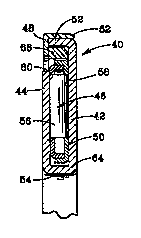
Thrust bearing assembly 40 of Figure 2
illustrates a~ embodiment of the present invention
comprising f irst th~^ust washer 42, second thrust washer
44, roller and roller cage subassembly 46, and outer cup
48 .
Roller cage 50 of subassembly 46 is radially
spaced from axially directed annular first flange 52,
integrally formed with first thrust washer 42, and is
adjacent to axially directed annular second flange 54,
integrally formed with second thrust washer 44. Rollers
56 of subassembly 46 roll on first raceway 58 and second
raceway 60 of radially directed portions of first and
second thrust washeræ 42 and 44, respectively. Thrust
bearing assembly 4C may be held together by various
means, such as, for example, lip 62 of outer cup 48 and
lip 64 on second flarlge 54 which wrap around first thrust
washer 42 and roller cage 50, respectively. Lips 62 and
64 may be formed by spinning, dimpling, staking or other
means .
The radial. space between roller cage 50 and
first flange 52 is sufficient to contain a friction
reducing element, such as first bushing 66, for example,
for improved piloting of subassembly 46. First bushing
.

Wo gs/27l49 2 ~ 8 1 4 4 2 PCT/US94/07700
66 may be molded of a suitable polymer, such as, for
example, polyetheretherketsne or VESPEL (available from
DuPont, Wilmington, Delaware), or may be m~-hin~f~ or
otherwise formed of bronze or other material pro~iding
5 low friction and low wear for sliding contact with
adjacent elements of the bearing assembly, such as, for
example, first thrust washer 42, roller cage 50 and outer
cup 48. If desired, additional piloting of roller cage
50 may be provided by sliding engagement with second
10 flange 54.
As best shown in Figure 3, first bushing 66 may
have beveled surface 68 or may be otherwise configured to
provide clearance f or an internal radius connecting the
radially directed portion of first thrust washer 42
15 (including first raceway 58) with the axially directed
portion forming first flange 52. The radial thickness
and the axial length of first bushing 66 depend on the
size, speed of rotation and load of thrust bearing
assembly 40. For a typical configuration with a 2-inch
20 outside diameter, for example, the radial thickness and
axial length may be, 0.030 and 0.250 inches,
respectively .
Thrust bearing assembly 70 of Figure 4
illustrates a second embodiment of the present invention
25 similar to thrust bearing assembly 40. In addition to
first bushing 66, thrust bearing assembly 70 includes a
second friction reducing element, such as second bushing
72, for example, between second flange 54 and roller cage
74, to further improve piloting of roller cage 74.
30 Compared to subassembly 46 of Figure 2, subassembly 76 of
Figure 4 provides increased radial clearance between
roller cage 74 and second f lange 54 f or location of
second bushing 72.
In addition to the configurations of Figures 2
35 and 4, the present invention may employ a single friction
reducing element for piloting a roller and roller cage
subassembly at its inside diameter. In that

Wo 95/27149 2 1 8 1 4 4 2 PCrNS94/07700
configuration, secorld bushing 72, for example, would be
used without first bushing 66. The roller cage for that
configuration would have a modified form to position the
rollers on the desired raceway surfaces and to provide a
5 desired radial spacing at its outside diameter to
facilitate additional piloting or other requirements.
Figure 5 illustrates a third embodiment of the
present invention similar to that of Figures 2 and 4 but
incorporating a di Eferent type of friction reducing
10 element. In place of first bushing 66, thrust bearing
assembly 80 includes a plurality of rolling elements such
as, for example, needle rollers or balls 82, within
retainer or cage 84, to reduce friction during piloting
of roller cage 50. Balls 82 provide rolling contact with
15 first thrust washer 42 and roller cage 50, further
reducing friction. A rolling element friction reducing
means may also be employed in place of second bushing 72.
The present invention is applicable to a wide
range of thrust be~aring configurations with various types
20 of roller cages. The bushing or other friction reducing
elemerlt may be positioned between the roller cage and
piloting flange of any thrust washer to effect the
present invention. The piloting flange may be a separate
annular axially directed surface rigidly attached to the
25 thrust washer or may be integrally formed with the thrust
washer by bending, crimping, machining or other means.
From the above description, it will be apparent
that the present inv,-ntion provides improved piloting of
a roller and roller cage subassembly in many forms of
30 thrust bearing assem~lies. Heat, wear and dra-g resulting
from friction between elements of the thrust bearing
assembly are substantially reduced. In addition, the
present invention may permit higher rotational speed of
the thrust bearing assembly and increased out-of-square
35 geometry of backup members or eccentricity of the
elements of the thrust bearing assembly.

Representative Drawing
A single figure which represents the drawing illustrating the invention.
Administrative Status

2024-08-01:As part of the Next Generation Patents (NGP) transition, the Canadian Patents Database (CPD) now contains a more detailed Event History, which replicates the Event Log of our new back-office solution.

Please note that "Inactive:" events refers to events no longer in use in our new back-office solution.

For a clearer understanding of the status of the application/patent presented on this page, the site Disclaimer , as well as the definitions for Patent , Event History , Maintenance Fee  and Payment History  should be consulted.

Event History

Description Date
Time Limit for Reversal Expired 1999-07-12
Application Not Reinstated by Deadline 1999-07-12
Deemed Abandoned - Failure to Respond to Maintenance Fee Notice 1998-07-13
Application Published (Open to Public Inspection) 1995-10-12

Abandonment History

Abandonment Date Reason Reinstatement Date
1998-07-13

Maintenance Fee

The last payment was received on 1997-06-19

Note : If the full payment has not been received on or before the date indicated, a further fee may be required which may be one of the following

  • the reinstatement fee;
  • the late payment fee; or
  • additional fee to reverse deemed expiry.

Patent fees are adjusted on the 1st of January every year. The amounts above are the current amounts if received by December 31 of the current year.
Please refer to the CIPO Patent Fees web page to see all current fee amounts.

Fee History

Fee Type Anniversary Year Due Date Paid Date
MF (application, 3rd anniv.) - standard 03 1997-07-11 1997-06-19
Owners on Record

Note: Records showing the ownership history in alphabetical order.

Current Owners on Record
THE TORRINGTON COMPANY
Past Owners on Record
THOMAS G. RHOADS
Past Owners that do not appear in the "Owners on Record" listing will appear in other documentation within the application.
Documents

To view selected files, please enter reCAPTCHA code :


To view images, click a link in the Document Description column. To download the documents, select one or more checkboxes in the first column and then click the "Download Selected in PDF format (Zip Archive)" or the "Download Selected as Single PDF" button.

List of published and non-published patent-specific documents on the CPD .

If you have any difficulty accessing content, you can call the Client Service Centre at 1-866-997-1936 or send them an e-mail at CIPO Client Service Centre.


Document
Description 
Date
(yyyy-mm-dd) 
Number of pages   Size of Image (KB) 
Abstract 1995-10-11 1 38
Description 1995-10-11 5 216
Drawings 1995-10-11 1 43
Claims 1995-10-11 3 93
Representative drawing 1997-07-01 1 5
Courtesy - Abandonment Letter (Maintenance Fee) 1998-08-09 1 189
Fees 1996-07-16 1 43
International preliminary examination report 1996-07-16 11 240