Note: Descriptions are shown in the official language in which they were submitted.
2181510
ATTORNEY
DOCRET NO. 2030
ADIABATIC SATURATOR AND METHOD FOR CONDITIONING AN AIR STREAM
Backqround Of The Invention
The present invention relates generally to an apparatus and
process for continuously providing air at a predetermined
temperature and humidity. More specifically, the present invention
relates to an adiabatic saturator air supply system for supplying
air at predetermined psychrometric conditions.
Air supply systems are typically made to clean and condition
air flowing through buildings, rooms, or equipment. These air
systems employ various devices to filter, heat, cool, humidify or
dehumidify air, including dry filters, electrostatic precipitators,
burners, heating coils, sprayed coils, cooling coils, wetted media,
steam injection, and other apparatus. These devices are used in
various combinations depending upon ambient conditions and the
target conditions. Specifically, these air systems typically
require that both temperature and relative humidity be continually
monitored in order to assure the desired air quality.
Currently available air supply systems use programmable
control loops that automatically monitor both temperature and
humidity, requiring complex controls for the entire system. These
process controls are also bulky and typically expensive, decreasing
the practicality of the underlying applications.
Controlling the relative humidity of an air supply is
particularly difficult because relative humidity is a function of
both temperature and absolute humidity, and both have been required
2 1 ~
ATTORNEY
DOCRET NO. 2030
to be controlled in the past. These controls can be expensive and
difficult to use. For example, "wet-bulb" thermometers are less
reliable than ordinary "dry-bulb" thermometers, and are subject to
problems (such as drying out of the wick) that dry-bulb
thermometers do not experience. (Throughout this application, a
reference to "temperature" means dry-bulb temperature; where the
"wet-bulb" temperature is intended to be referenced, it will be
specified.) Also, systems requiring both temperature and
absolute humidity measurement may not be capable of operating in
both summer and winter conditions (i.e. when inlet air has either
a significantly higher or lower temperature and/or humidity than
the desired application conditions).
The solution to these problems which forms the subject of the
present invention will be described with reference to the
conditioning of an air stream flowing through a paint spray booth.
An example of one such paint spray booth is described in U.S.
Patent No. 4,222,319. Canadian patent file number , filed
July 18, 1996, and entitled Integrated Paint Spray Booth And Air
Conditioning System And Process, discloses a unique arrangement of
component equipment constituting a compact, space-efficient
integrated paint spray booth and air conditioning system. However,
it will be apparent to those of ordinary skill in the art that the
present
2181~10
ATTORNEY
DOCKET NO. 2030
invention can be successfully adapted for use in conditioning an
air stream used in a wide variety of other applications, as well.
Relatively specific and strïngent psychrometric values may be
required of air supply systems such as those used in waterborne and
powder paint spray booth applications. This is due to the
comparatively narrow window of psychrometric conditions that are
acceptable for waterborne and powder paint applications te.g.,
about 65F/60~ RH for powder paint, and about 70F/70~ RH for
waterborne paint). Various techniques have been developed to
provide humidity control systems for paint spray booth
applications. However, these previous systems have required the
monitoring and maintenance of both the desired relative humidity
and temperature levels for the air within the controlled system.
These multi-variable processes require complex control systems to
achieve the preselected filtered, psychrometric conditions
necessary for the introduction of an air stream into a spray booth.
These systems or "air supply houses" are also relatively large
structures taking approximately one-third of the space required for
the spray booth and adding additional floors above the spray booth,
thus decreasing the practicality and cost effectiveness of the
paint facility.
Another disadvantage associated with available air supply
control systems adapted for use in paint spray booths is that they
have proven difficult to operate in both summer and winter
- ~181$1G
ATTORNEY
DOCRET NO . 2 0 3 O
conditions. Further, paint spray booths require the conditioning
and filtering of large volumes of air (e.g., 500,000 eubic feet per
minute), with a corresponding `expenditure of energy. It is
therefore desirable both to recover energy from the exhaust air,
and to minimize the air volume required to undergo conditioning.
Accordingly, there is a need for an air conditioning system
that minimizes the need for control systems, thereby decreasing
costs, and that can operate under a wide variety of operating
conditions in an economical fashion.
Summary of the Invention
Accordingly, it is an object of the present invention to
provide an air supply system for applications requiring the use of
air having a controlled temperature and humidity.
Another object of the invention is to provide a system that
accomplishes the adiabatic saturation of an air stream without the
need for directly measuring relative humidity.
A further object of the invention is to provide a system that
can minimize the flow rate of air requiring conditioning by
recirculating processed air within the system.
Still a further object of the invention is to provide a method
for conditioning an air stream that is more economical than
existing air control systems.
21~151~
ATTORNEY
DOCKET NO. 2030
In accordance with a preferred embodiment of the present
invention, an apparatus for conditioning an air stream to provide
the air stream to an operati-on~ area at desired, predetermined
temperature and relative humidity levels lS provided. The
apparatus includes an adiabatic saturator through which the air
stream and water flows. The water intimately mixes with the air
stream within the saturator, resulting in an air stream exiting the
saturator which is completely saturated with water, which has a
temperature equal to the temperature of the water entering the
saturator, and which has been scrubbed of particulate contaminants.
A first temperature sensor is positioned to measure the temperature
of the air stream exiting the saturator. A heater (such as a
heating coil or a burner) or a cooling coil is located upstream of
the saturator, for selectively heating the air stream or chilling
water and pumping the water through a cooling coil to cool the air
prior to its entry into the saturator, in response to the
temperature measurement from the first temperature sensor, and is
useful when the volume of air flow within the conditioning system
is not constant. Preferably, however, a cooling coil is not used
since the air can be directly cooled within the saturator.
In a preferred embodiment, the air stream can be reheated
after it exits the saturator to increase its temperature and reduce
its relative humidity to the desired, predetermined levels. In
this embodiment, a second temperature sensor is positioned to
1 0
~ TTORNEY
DOCRET NO . 2 0 3 0
measure the temperature of the air stream downstream of the
saturator and after it has been reheated. The reheater is
adjustably responsive to the temperature measurement of the second
temperature sensor.
In the particularly preferred embodiment, the adiabatic
saturator includes a spray tower containing packing elements. The
packing elements enhance the heat transfer and saturation of the
air stream improving the mixing an intimate contact between the
water and the air stream within the spray tower.
A process for conditioning an air stream to provide the air
stream to an operation area at desired, predetermined temperature
and relative humidity levels also forms a part of the present
invention. First, a continuous flow of air and water is maintained
through an adiabatic chamber. The air stream and the water within
the chamber intimately mixes so that the air stream is saturated
with water and the temperature of the air stream exiting the
chamber is approximately equal to the temperature of the water
entering the chamber. Next, the temperature of the air stream
exiting the saturator is measured with a first temperature sensor.
The air stream or the water, prior to its entry to the chamber, can
be selectively heated or chilled, in response to the temperature
measurement of the first temperature sensor. After the air stream
exits the adiabatic chamber, the air stream can be reheated; the
temperature of this air stream can be measured by a second
a ~
ATTORNEY
DOC~ET NO. 2030
temperature sensor, and the amount of reheating can be selectively
controlled to account for changes in the volume of air flow through
the system. Preferably, the-amount of reheating is kept at a
constant rate if the air flow can be maintained at a relatively
constant rate, further minimizing process controls.
In an alternative embodiment of the process of the present
invention, varying proportions of ambient air and air from the
operation area can be selectively recirculated to the adiabatic
chamber. Also, the water exiting the chamber can be recirculated
back through the chamber.
Brief Description of the Drawings
The novel features which are characteristic of the present
invention are set forth in the appended claims. The invention
itself, however, together with further objects and attendant
advantages, will be best understood by reference to the following
description taken in connection with the accompanying drawings in
which: .
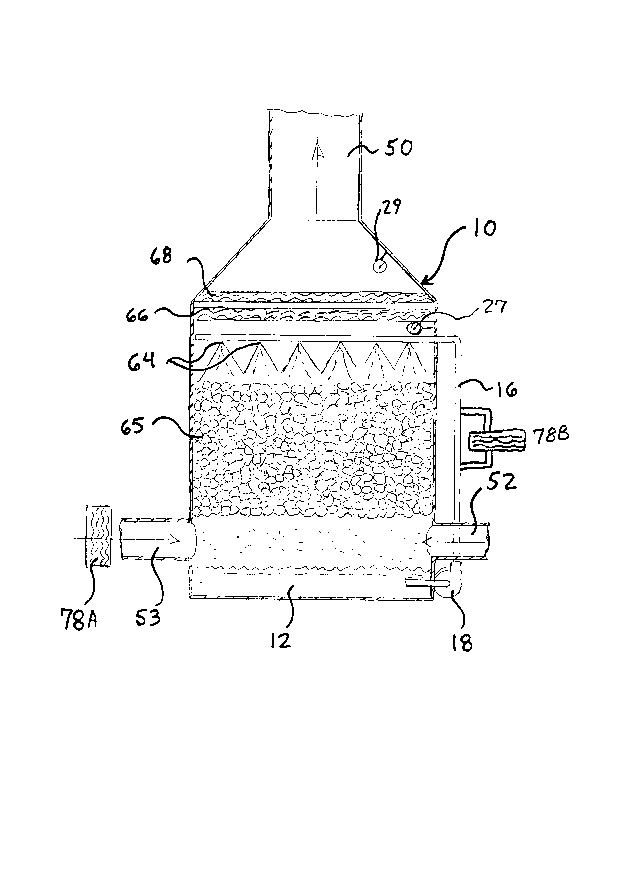
FIGURE 1 is a side cross-sectional view of the preferred
embodiment of the adiabatic saturator of the present invention, a
packed spray tower;
FIGURE 2 is a schematic, cross-sectional view of an integrated
spray booth and air conditioning system that constitutes one
application of the present invention;
Zl~10
ATTORNEY
DOC~ET NO. 2030
FIGURE 3 is a sehematie diagram of the proeess steps of a
preferred embodiment of the present invention; and
FIGURE 4 is a thermodynamie~ehart i~llustrating the effeet of
summer and winter eonditions on the adiabatie saturator.
Detailed Description of the Preferred Embodiment
An air eonditioning chamber or apparatus, preferably
eonsisting of a paeked spray tower, is designated generally as 10
in FIGURE 1. The upper portion of air conditioning ehamber 10 is
in fluid communication with duct 50, which eonveys properly
conditioned air to an operation area, such as the paint spray
operation shown in FIGURE 2 and described below.
Air conditioning apparatus 10 is an adiabatic saturator, a
device in which heat is neither gained or lost. With an adiabatie
saturator, the heat of vaporization for the water that is
evaporated is supplied by the eooling of the air passing through
the saturator. The wet-bulb temperature of the air stream is
eonstant throughout the ehamber, and the weight of water evaporated
equals the inerease in the specific humidity of the air within the
ehamber. Tower 10 should be constructed to be suffieiently large
so that the air stream exiting the chamber will be saturated at the
wet-bulb temperature of the air stream entering the ehamber.
Packed spray tower 10 shown in FIGURE 1 aeeommodates
tspelling] a downward flow of water provided by spray nozzles 64 to
1 0
ATTORNEY
DOCRET NO. 2030
thereby properly condition the upwardly flowing air mass through
the saturator to a prescribed and predetermined temperature and
humidity. The water flow is recirculated~within saturator/tower 10
by pump 18, which continually delivers the water to spray nozzles
64 from holding tank 12. Thus, within tower 10 the air stream is
brought into contact with water for a suitable duration so that the
air becomes saturated with moisture (i.e., it has 100% relative
humidity), and the wet-bulb temperature of the air stream exiting
the tower approximately equals the temperature of the water
entering the tower (differing only by radiation and velocity errors
that affect the wet-bulb thermometer). The air exit stream then
contacts heat exchanger 68, which preferably adds a constant amount
of heat to the air stream to alter the air stream to the desired
psychrometric conditions. Because the heat added to the air exit
stream is constant, provided the air stream flow remains constant,
process controls are minimized.
Still referring to FIGURE 1, spray tower 10 is preferably
preceded by a burner to warm the entering air stream (e.g., heat
exchanger 78A), primarily to avoid freezing of the water in winter
conditions. Heat exchanger 68 is used to warm the air stream
exiting the tower to the desired temperature, while simultaneously
reducing its relative humidity to the desired value.
While in the preferred embodiment adiabatic saturation is
achieved by adjusting the temperature of the inlet air stream to a
21~1~10
ATTORNEY
DOCRET NO. 2030
wet-bulb temperature equal to the temperature of the fluid stream
entering the saturator, it should be appreciated that,
alternatively, adiabatic saturat~ion can be achieved by adjusting
the temperature of the fluid stream to equal the wet-bulb
temperature of the air stream exiting the saturator. Either
process results in an air stream having a known temperature and a
known relative humidity without the need for monitoring any
parameter other than the temperature of the air stream.
In the preferred embodiment of the present invention,
adiabatic saturation of the supply air takes place in packed spray
tower 10 containing packing elements 65. The water impacts packing
elements 14 within saturator 10, intimately mixing with and
"scrubbing" the counter-current air stream. (Cross-streams or even
unidirectional streams of air and water can also be used, though a
counter-current air stream is preferred, as discussed below.)
Packed spray tower 10 permits contaminants to be removed from the
air stream (they are transferred to the water) while simultaneously
conditioning the air stream in the manner described above. In
addition, a demister 66 and a reheater 68 may be positioned
downstream of adiabatic saturator 10. The scrubbing fluid to be
used should be water, since the use of fluids other than water
would require the measurement of humidity, in contravention to the
teaching of the present invention.
151~ .
ATTORNEY
DOCRET NO. 2030
The packing elements 65 within spray tower 10 may be a plastic
material of the type disclosed in U.S. Patent No. 4,668,442 and
sold as NuPac~ Tower Packing-by Lantec~Products Inc. of Agoura
Hills, California. This packing element is currently preferred
because of its high scrubbing efficiency and its high resistance to
fouling or plugging. The packing elements enhance the heat
transfer and humidification effects of the water on the air stream
within the spray tower, for as the water contacts the packing
elements, it surrounds and wets them, increasing the surface area
of the water which is in direct, intimate contact with the flowing
air stream.
As one example, for a constant air flow through an adiabatic
packed spray tower of 500 feet/minute, and given a constant liquid
water flow of 8 gallons/minutes/square foot, a packed bed length of
4 feet has been found to permit inlet air ranging in temperature
from 0F to 100F to be properly conditioned for introduction into
a paint spray booth. The capital cost for this filtering and air
conditioning system has been estimated to be between about $1.00
and $1.50 per cubic foot/minute.
Referring now to FIGURE 2, a preferred embodiment of the
present invention, an integrated paint spray booth and air
conditioning system, is designated generally as 15 and is
schematically illustrated. The system 15 includes as its basic
components a spray booth housing 20, a scrubber chamber 30, a
11
2181510
ATTORNEY
DOC~ET NO. 2030
filtering chamber 40, a duct 50, an air conditioning apparatus 10,
and an air circulating means, such as blower or fan 70. Saturator
receives recirculating ai-r ~from the spray booth operation
through inlet 52 located in a lower portion of saturator 10. A
fresh air stream may also be introduced via filter 63 into
saturator 62 and mixes with the circulating air in the system and
the downward flow of water.
The spray booth housing 20 defines a paint application zone 22
through which the automotive bodies or other articles to be painted
pass sequentially. Housing 20 includes opposing side walls 24 and
a top 26 and bottom 28 each of which includes one or more air
passages to accommodate a downward flow of the air through the
paint application zone 22. The scrubber chamber 30 extends
longitudinally beneath the paint spray booth housing 20 and
includes an inlet comprised of a plurality of longitudinally spaced
cylinders 34 which receive air discharged from the spray booth, and
terminate in a scrubber outlet 36. The air flow exiting scrubber
chamber 30, now laden with various contaminant particles acquired
within operation area 32 of the paint spray booth, enters into
filtering chamber 40 and passes through a plurality of filter
elements 42. Downstream of air filters 42, on the side of the
filtering chamber opposite to the scrubber chamber, is a discharge
plenum 46 in fluid communication with duct 50. Inlet 52 permits
the air stream to flow up through saturator 10 to duct 50, which
12
218~.Sl.~
ATTORNEY
DOCRET NO . 2 0 3 0
extends a sufficient vertical height to permit the circulation of
air to the top of the spray booth 20.
After the air supply stream is adiabatically saturated, the
air supply stream then passes through demister 66, which removes
water droplets carried by the air stream. Next, the air supply
stream passes through heat exchanger 68 to bring the air to the
desired temperature and relative humidity, thus placing the air
stream within the desired psychrometric "window." The air stream
then circulates through duct work 50 by means of fan 70, which also
acts to offset any pressure drop that occurs within the tower. Fan
70 may then draw the air stream into a supply plenum 48 and through
additional bag filters, if necessary. Supply plenum 48 provides
for the even introduction of the air stream across operation area
32 during operation.
An exhaust duct 80 may also be employed, and is preferably
located to communicate with the system at the plenum disposed
between filtering chamber 40 and the inlet 52 to duct 50. An
exhaust fan 82 discharges the exhausted air to atmosphere.
Automatically controlled dampers 61 and 84 can be employed to
balance the air flow in the system by adjusting the quantity of
fresh air introduced into the system and/or the quantity of system
air that is exhausted. Alternatively, additional treatment of the
air upon its exit from operation area 32 may be necessary.
218151 Q
ATTO~NEY
DOCRET ~O . 2 0 3 0
By simply spraying water into the plenum or duct 50 (shown in
FIGURE 2), the adiabatic saturation of the air stream can be
achieved. One advantage of thi-s embodiment is that it generates a
relatively small pressure drop, thus resulting in lower operating
costs. The disadvantage, however, is that duct 50 may be required
to be extremely long for a given application. For example, in the
context of a paint spray booth, it has been found that a packed
spray tower having a bed length of four feet is acceptable for
treating air ranging from approximately 32F and 0% relative
humidity to approximately 90F and 100~ relative humidity. By
contrast, it is believed that a comparable unpacked tower would be
required to be over 25 feet in length. This results in undesired
increases in capital costs, weight and operating space.
It will now be appreciated that, in accordance with the
present invention, only controls for measuring temperature, not
humidity, are required, and the need for humidity or moisture
sensors is eliminated. Referring to FIGURE 1, one temperature
sensor 27 is positioned immediately downstream of the saturator and
upstream of reheater 68. Temperature sensor 27 thus monitors the
saturated air temperature; in a winter condition (for example),
either the air entering the saturator or the water in or supplied
to the saturator can be heated to obtain the desired temperature of
the air stream, depending on the input from sensor 27. In
addition, a second temperature sensor 29 can be positioned within
14
218~1C
ATTORNEY
DOC~CET NO . 2 0 3 0
duct 50 immediately downstream of reheater 68; this temperature
measurement permits the adjustment of the amount of heat from the
reheater, ensuring an adequate-amount of~reheat, given changes in
the volume of air flow. (Volumetric air flow changes can occur
within the system for various reasons, including changes in the
operation, the amount of recirculation of the air stream, the
damper mechanisms, etc.) With these two simple and inexpensive
temperature sensors 27 and 29, which need only be ordinary
thermometers, complete psychrometric control over the air stream is
obtained. Because the temperature of the incoming ambient air can
also vary during the day, in either summer of winter conditions,
and the air stream volume can also vary, constant temperature
monitoring of the air stream exiting the saturator should be
performed.
All or part of the air stream can be recirculated and
introduced back into packed tower 10, or it can be removed through
exhaust duct 80 by exhaust fan 82, where the air can be processed
for further treatment of (e.g.) volatile organic compounds. The
amount of recirculation necessary for the system is dependant upon
at least two factors. First, in extremely cold weather conditions,
it may be necessary to heat fresh air entering saturator 10. An
increased amount of recirculated air would minimize the energy
requirements for heating the fresh air stream to be introduced into
the saturator. Minimizing the portion of the air stream being
~81~
P.TTORNEY
DOCRET NO . 2 0 3 0
removed through the exhaust also minimizes the energy requirements
and cost of any secondary air treatment processes that might be
used. - ~ ~
A second counterbalancing factor to be considered in
determining the amount of recirculated air to be used is the nature
and amount of contaminants built up within the system. Some
applications may not require extensive human exposure to the
operation area. Thus, there may not be an overriding concern of
taking in "fresh" air. However, by increasing the amount of
recirculated air within the system, the amount of potential
contaminants within the air stream increases, possibly creating
potential environmental or safety risks within the system, given
the application. Approximately 0-90% by volume air stream
recirculation is preferred for the particular application of a
paint spray booth, to ensure non-explosive conditions for the paint
solvent.
The ability of the present air supply system to deal with
varying conditions is shown by reference to the following examples
together with FIGURE 4. In these examples the desired
psychrometric conditions are 70F and 70~ relative humidity under
both winter and summer conditions. The examples are intended to be
illustrative and should not be considered as limitations on the
claimed invention.
Example 1 -- Winter Conditions
16
2~ 21$1~
ATTORNEY
DOCRET NO. 2030
As shown in line 1 of FIGURE 4, a constant flow of air is
brought into tower 10 at a temperature of 40F and 10% relative
humidity (shown as point A), and air is pretreated with a burner so
that it is heated to approximately 106F and a wet bulb temperature
of 60F (shown as point B). The air is then saturated, and exits
tower 10 at approximately 60F and 100% relative humidity (point
C). This exit air stream then passes through heat exchanger 68,
which provides the air stream with a constant amount of reheat
(approximately 3 Btu/lb dry air) to produce the desired air stream
at approximately 70% relative humidity and 70F (point D).
Example 2 -- Summer Conditions
As shown in line 2 of FIGURE 4, a constant flow of air is
brought into tower 10 at a temperature of 90F and 85% relative
humidity (shown as point E), and the water in tower 10 is treated
with a chiller (not shown) so that the exit air stream is brought
down to a temperature of 60F and a relative humidity of 100%
(shown as point C). The exit air steam then passes through heat
exchanger 24, which provides the air stream with a constant amount
of reheat to produce the resulting air stream at 70% relative
humidity and 70F (point D).
Chilling the water avoids the need for a separate cooling coil
during summer to cool air prior to its introduction into the tower.
Rather, the present system preferably compensates for the air inlet
temperature using chilled water within the system, thus creating a
17
'- ' ' . ~181~1q ,-
ATTORNEY
DOCXET NO. 2030
more efficient heat exchange and reducing the capital cost of the
system. Alternatively, the air stream may be cooled prior to
saturation, but cooling the ai~ is less thermodynamically efficient
than chilling the water.
The use of counter-current air and fluid streams (i.e.,
streams in parallel but opposite directions) is preferred. The air
stream exiting saturator 10, as well as the fluid stream entering
saturator 10, have a constant temperature across the cross-section
of each exiting stream. This results in a constant temperature
profile for the exiting air stream and avoids temperature
stratification of the exiting streams (i.e., different temperatures
in different regions along the cross-section of the exiting stream,
which occurs when the air and fluid stream directions are normal to
each other). Temperature stratification can result in certain
regions of the air stream being outside the desired psychrometric
conditions (although the average psychrometric levels of the
overall air stream will be within the desired levels). Temperature
stratification may therefore require the use of further devices to
mix the air.
A process for providing an air stream at preselected
temperature and relative humidity values also forms part of the
present invention. Referring now to FIGURE 3, an initial step in
the process (represented by block 48) involves saturating an air
stream by scrubbing the air stream with a fluid such as water
18
- 218~51~
ATTORNEY
DOCRET NO . 2 O 3 O
maintained at the desired wet-bulb temperature sought for the air
stream. Next, the air stream is preferably reheated with a
predetermined, constant amount- of heat ~see block 50). Now, the
air stream is introduced into an operation area (block 52).
Preferably (referring now to block 54), a portion of the "used" air
stream can now be recirculated back to be saturated (block 48).
During cold weather conditions, fresh air can be heated (block 56)
by a heating coil or burner prior to saturating the air. In summer
conditions, the fresh air can be chilled (e.g. with water) prior to
saturating it, or (preferably) the fluid can be chilled (block 59).
It should be understood that in an alternative embodiment of
the present invention, reheating of the air stream exiting the
saturator may not be required (i.e., 100~ RH may be within the
psychrometric window given the application). Alternatively, a
reheater can be used but a temperature sensor positioned downstream
of the reheater need not be used, since volumetric changes in the
air stream may not need to be accounted for in a given application.
Of course, it should be noted that various changes and
modifications to the preferred embodiments of this invention will
be apparent to those skilled in the art. Such changes and
modifications can be made without departing from the spirit and
scope of the present invention. For instance, wetted media or
sprayed coils can be used to achieve adiabatic saturation within
packed or unpacked towers. Further, the broad teaching of the
19
- 2~81~1~
ATTORNEY
DOC~ET NO . 2 O 3 O
present invention of conditioning an air stream to adiabatic
saturation is obviously not limited to the conditioning of air used
for paint spray booths, but can also be used with other operations
that require the conditioning of air. It is, therefore, intended
that such changes and modifications be covered by the following
claims.