Language selection

Search

Patent 2181650 Summary

Third-party information liability

Some of the information on this Web page has been provided by external sources. The Government of Canada is not responsible for the accuracy, reliability or currency of the information supplied by external sources. Users wishing to rely upon this information should consult directly with the source of the information. Content provided by external sources is not subject to official languages, privacy and accessibility requirements.

Claims and Abstract availability

Any discrepancies in the text and image of the Claims and Abstract are due to differing posting times. Text of the Claims and Abstract are posted:

  • At the time the application is open to public inspection;
  • At the time of issue of the patent (grant).
(12) Patent Application: (11) CA 2181650
(54) English Title: SPOUT WITH HUB
(54) French Title: BEC AVEC PARTIE FEMELLE
Status: Deemed Abandoned and Beyond the Period of Reinstatement - Pending Response to Notice of Disregarded Communication
Bibliographic Data
(51) International Patent Classification (IPC):
  • B05B 01/22 (2006.01)
  • E03C 01/02 (2006.01)
  • E03C 01/04 (2006.01)
(72) Inventors :
  • CHING, FRED Y. F. (United States of America)
  • EVANS, MATTHEW J. (United States of America)
  • GURR, CHRISTOPHER G. (United States of America)
(73) Owners :
  • EMHART INC.
(71) Applicants :
  • EMHART INC. (United States of America)
(74) Agent: SWABEY OGILVY RENAULT
(74) Associate agent:
(45) Issued:
(22) Filed Date: 1996-07-19
(41) Open to Public Inspection: 1997-03-29
Availability of licence: N/A
Dedicated to the Public: N/A
(25) Language of filing: English

Patent Cooperation Treaty (PCT): No

(30) Application Priority Data:
Application No. Country/Territory Date
08/535,689 (United States of America) 1995-09-28

Abstracts

English Abstract


A single-piece tube 20 is formed to include a hub 30 at first
end 26 of the tube with a spout 44 extending from the hub to a
second 28 of the tube. A tapered transition surface 38 extends
between the hub 30 and the spout 44. A bevel 34 is formed at the
base of the hub 30 on an outer surface 22 thereof adjacent the end
26 of the tube 20. An annular bead 36 is formed on the outer
surface 22 of the hub 30 at a location spaced from the bevel 34 to
define a space 46 between the bevel and the bead. A pair of bends
40 and 42 are formed in spaced portions of the spout 44. In
another embodiment, an annular groove 50 is formed in the outer
surface 22 of the hub 30 instead of the bevel 34 and the bead 36.
An O-ring 48 can be located in the space 46 or the groove 50. The
single-piece tube 20 formed with the hub 30 and the spout 44 can be
assembled with a water mixing facility 56.


Claims

Note: Claims are shown in the official language in which they were submitted.

The embodiments of the invention in which an exclusive property
or privilege is claimed are defined as follows:
1. A spout with hub, which comprises:
a tube formed from a single piece of material;
the tube formed with a first section having a first diameter
defining a spout;
the tube formed with a second section having a second diameter
larger than the first diameter defining a hub;
the hub of the tube being located at and extending inward from
a first end of the tube;
the spout of the tube extending from the hub to a second end
of the tube; and
a defined space formed on an outer surface of the hub for
ultimate receipt of a compliant element.
2. The spout with hub as set forth in claim 1, wherein the
defined space is formed in part by a bead formed around the outer
surface of the hub.
3. The spout with hub as set forth in claim 1, wherein the
defined space is formed in part by a bevel formed in the outer
surface of the hub.
4. The spout with hub as set forth in claim 3, wherein the
bevel is located at the first end of the tube.
5. The spout with hub as set forth in claim 1, wherein the
defined space is located between a bead formed at a first location
around the outer surface of the hub and a bevel formed at a second
location on the hub spaced from the first location.
6. The spout with hub as set forth in claim 1, wherein an
annular groove is formed in the outer surface of the hub to provide
the defined space.
7. The spout with hub as set forth in claim 1, which further
comprises:
the tube being formed with a transition surface between the
first section and the second section thereof.
8. The spout with hub as set forth in claim 7, wherein the
transition surface is a tapered section extending between the hub
and the spout of the tube.

9. The spout with hub as set forth in claim 1, wherein the
spout of the tube is formed with angular bends in at least two
spaced sections thereof.
10. The spout with hub as set forth in claim 1, wherein the
material from which the tube is formed is a copper alloy.

Description

Note: Descriptions are shown in the official language in which they were submitted.


2~81650
Doc No. 4861-25
SPOUT WITH HUB
BACKGROUND OF THE INVENTION
This invention relates to a spout with a hub and particularly
relates to a spout with a hub which is formed from a single tube.
In many instances, spouts which form an element of a kitchen
faucet include a metallic hub-and a metallic spout tube which are
joined together by a metal-to-metal bonding such as brazing. The
hub and the spout tube are formed with fluid passages which are in
communication to facilitate the flow of water therethrough.
When manufacturing the hub, various forming and mac-hining
operations are required. Also, the spout tube requires several
steps in the manufacture of the spout for assembly with the hub.
The hub and the spout must then be processed through a bonding
procedure. The processes practiced in making such a hub and spout,
and then assembling the hub and spout, are time consuming and
costly.
Thus, there is a need for a simplified and less costly manner
of making a spout and hub assembly for forming a portion of a
faucet.
SUMMARY OF THE INVENTION
It is, therefore, an object of this invention to provide a
inexpensive spout with hub which is relatively simple to
~ nufacture.
C Another object of this invention is to provide a spout with
hub which is easily assembled with other elements to form a faucet.
With these and other objects in mind, this invention
contemplates a spout with hub having a -first tubular portion of a
first diameter joined integrally with a second tubular of a second
diameter larger than the first diameter.

- 2 1 8 1 650
This invention further contemplates a spout with hub in which
the spout is formed in a section of a tube and the hub is formed in
an adjoining section of the tube.
Other objects, features and advantages of the present
invention will become more fully apparent from the following
detailed description of the preferred embodiment, the appended
claims and the accompanying drawings.
BRIEF DESCRIPTION OF THE DRAWIN~S
In the accompanying drawings:
Fig. 1 is a side view of a cylindrical tube;
Fig. 2 is an end view of the cylindrical tube of Fig. 1;
Fig. 3 is a side view of a portion of the tube of Fig. 1
formed in the configuration of a spout with a hub in accordance
with certain principles of the invention;
Fig. 4 is a side view of the formed spout and hub of Fig. 3
with a straight section removed for illustration purposes;
Fig. 5 is a side view of a portion of the tube of Fig. 1
formed in the configuration of another embodiment of a spout with
a hub in accordance with certain principles of the invention; and
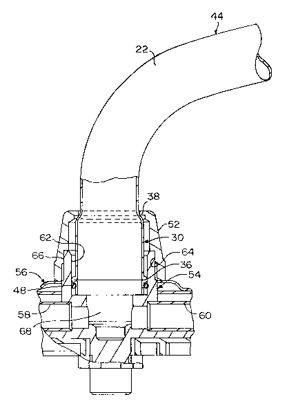
Fig. 6 is a sectional view showing the spout with hub of Fig.
3 in assembly with a water mixing facility.
DE~AILED DESCRIPTION OF THE PREFERRED EMBODIMENT
As shown in Figs. 1 and 2, a tube 20 is formed in a
cylindrical shape with a prescribed diameter. The tube 20 has an
outer surface 22, an internal surface 24 (Fig. 2), a first end 26
and a second end 28. The tube 20 is composed of a metal such as,
for example, a copper alloy which is the material used in the
preferred embodiment. Also, in the preferred embodiment, the tube
20 is about eleven inches in axial length, about three-fourths inch
in diameter and has an approximate wall thickness of 0.032 inch.
Tubes formed from other materials and having different dimensional
parameters than those of the preferred embodiment could be used
without departing from the spirit and scope of the invention.

2181650
Referring to Fig. 3, the tube 20 of Fig. 1 has been processed
through a reshaping procedure to enlarge a section of the tube
adjacent the end 26 thereof to form a cylindrical hub 30 with a
diameter which is larger than the prescribed diameter of the tube.
In particular, hub 30 has been enlarged to form a cylindrica
portion 32. A flared lip or bevel 34 is formed at the end 26 of
the tube 20. A rounded rib or bead 36 is formed around a lower
area of the cylindrical portion -32. A transition surface 38 is
formed between the cylindriGal portion 32 and the outer surface 22
of the portion of the tube 20-immediately adjacent and inboard of
the hub 30.
As shown in Fig. 4, the remainder of the tube 20 of Fig. 1 is
not enlarged but is formed with a pair of spaced bends 40 and 42 to
complete the formation of a spout 44. Thus, the spout 44 and the
hub 30 are formed from the single tube 20 and remain as a single
piece after the formation of-the spout and the hub. A space 46
(Fig. 3) is defined between the bevel 34 and the bead 36 for
receipt of an 0-ring 48 as shown in Fig. 4.
The embodiment illustrated in Fig. 3 represents the preferred
embodiment of the invention.
Another embodiment of the invention is shown in Fig. 5 where
instead of forming the bevel 34 and the bead 36 to define the space
46, an annular groove 50 is formed in the cylindrical portion 32 of
the hub 30 for receipt of the 0-ring 48 (Fig. 4). In this
embodiment, the hub 30 and the spout 44 are also formed from the
single piece of tube 20.
Referring to Fig. 6, a trim nut 52 is positioned over the end
28 (Fig. 4) of the spout 44 and moved to the position illustrated
in Fig. 6. The hub 30 is positioned adjacent a center body s4 of-
a water mixing facility 56. The center body 54 is connected to a
pair of conduits 58 and 60 which are connected to end bodies (not
shown) for supplying hot and cold water, respectively, to the
center body. The center body 54 is also formed with a cylindrical
shell 62 at the top the~eof for receipt of the lower end of the hub
30. After the hub 30 has been located in the shell 62 of the

2181650
center body 54, the trim nut 52 is manipulated so that threads 64
thereof are moved into engagement with threads 66 of the center
body to secure the hub with the center body. Water can then flow
from the conduits 58 and 60 to a chamber 68 of the center body 54
and then through the hub 30 and the spout 44 exiting at the end 28
(Fig. 4).
In general, the above-identified embodiments are not to be
construed as limiting the breadth of the present invention.
Modifications, and other alternative constructions, will be
apparent which are within the spirit and scope of the invention.as
defined in the appended claims.

Representative Drawing
A single figure which represents the drawing illustrating the invention.
Administrative Status

2024-08-01:As part of the Next Generation Patents (NGP) transition, the Canadian Patents Database (CPD) now contains a more detailed Event History, which replicates the Event Log of our new back-office solution.

Please note that "Inactive:" events refers to events no longer in use in our new back-office solution.

For a clearer understanding of the status of the application/patent presented on this page, the site Disclaimer , as well as the definitions for Patent , Event History , Maintenance Fee  and Payment History  should be consulted.

Event History

Description Date
Inactive: IPC from MCD 2006-03-12
Inactive: Cover page published 2000-12-20
Time Limit for Reversal Expired 1999-07-19
Application Not Reinstated by Deadline 1999-07-19
Deemed Abandoned - Failure to Respond to Maintenance Fee Notice 1998-07-20
Application Published (Open to Public Inspection) 1997-03-29

Abandonment History

Abandonment Date Reason Reinstatement Date
1998-07-20
Owners on Record

Note: Records showing the ownership history in alphabetical order.

Current Owners on Record
EMHART INC.
Past Owners on Record
CHRISTOPHER G. GURR
FRED Y. F. CHING
MATTHEW J. EVANS
Past Owners that do not appear in the "Owners on Record" listing will appear in other documentation within the application.
Documents

To view selected files, please enter reCAPTCHA code :


To view images, click a link in the Document Description column. To download the documents, select one or more checkboxes in the first column and then click the "Download Selected in PDF format (Zip Archive)" or the "Download Selected as Single PDF" button.

List of published and non-published patent-specific documents on the CPD .

If you have any difficulty accessing content, you can call the Client Service Centre at 1-866-997-1936 or send them an e-mail at CIPO Client Service Centre.


Document
Description 
Date
(yyyy-mm-dd) 
Number of pages   Size of Image (KB) 
Abstract 1996-10-21 1 25
Description 1996-10-21 4 169
Drawings 1996-10-21 3 38
Claims 1996-10-21 2 54
Representative drawing 1997-07-10 1 12
Representative drawing 2000-12-06 1 12
Reminder of maintenance fee due 1998-03-22 1 111
Courtesy - Abandonment Letter (Maintenance Fee) 1998-08-16 1 189