Language selection

Search

Patent 2181718 Summary

Third-party information liability

Some of the information on this Web page has been provided by external sources. The Government of Canada is not responsible for the accuracy, reliability or currency of the information supplied by external sources. Users wishing to rely upon this information should consult directly with the source of the information. Content provided by external sources is not subject to official languages, privacy and accessibility requirements.

Claims and Abstract availability

Any discrepancies in the text and image of the Claims and Abstract are due to differing posting times. Text of the Claims and Abstract are posted:

  • At the time the application is open to public inspection;
  • At the time of issue of the patent (grant).
(12) Patent Application: (11) CA 2181718
(54) English Title: WEAR ELEMENT FOR SCREW PRESSES OR THE LIKE
(54) French Title: ELEMENT D'USURE POUR PRESSES A VIS OU ANALOGUE
Status: Deemed Abandoned and Beyond the Period of Reinstatement - Pending Response to Notice of Disregarded Communication
Bibliographic Data
(51) International Patent Classification (IPC):
  • B30B 09/12 (2006.01)
  • B04B 01/20 (2006.01)
  • B30B 11/24 (2006.01)
  • B65G 33/26 (2006.01)
(72) Inventors :
  • OMMUNDSEN, DAG (Norway)
(73) Owners :
  • DAG OMMUNDSEN
(71) Applicants :
  • DAG OMMUNDSEN (Norway)
(74) Agent: SMART & BIGGAR LP
(74) Associate agent:
(45) Issued:
(86) PCT Filing Date: 1995-01-31
(87) Open to Public Inspection: 1995-08-10
Examination requested: 1999-06-03
Availability of licence: N/A
Dedicated to the Public: N/A
(25) Language of filing: English

Patent Cooperation Treaty (PCT): Yes
(86) PCT Filing Number: PCT/NO1995/000021
(87) International Publication Number: NO1995000021
(85) National Entry: 1996-07-19

(30) Application Priority Data:
Application No. Country/Territory Date
940330 (Norway) 1994-02-01

Abstracts

English Abstract


A wear element comprising a wear plate (2) of a hard, typically ceramic material, locked
in a dovetail recess (20) of a bracket (1) made of steel. The bracket (1) consists of two
initially separate parts (6', 6'') comprising a respective one of the two inclined dovetail wedge
surfaces (5', 5'') of the dovetail recess (20). The two parts (6', 6'') are welded together when
positioned with their respective wedge surfaces (5', 5'') tightly engaging a respective one of
two complementary inclined wedge surfaces (4', 4'') formed on the wear plate (2).


French Abstract

Elément d'usure comportant une plaque d'usure (2) en matière dure et normalement céramique bloquée dans l'évidement en queue d'aronde (20) d'un support (1) en acier. Le support (1) est composé de deux pièces initialement indépendantes (6', 6") comportant les faces en coin inclinées respectives (5', 5") de l'évidement en queue d'aronde (20). Ces deux pièces (6', 6") sont soudées l'une à l'autre lorsque leurs faces en coin respectives (5', 5") sont serrées contre des faces en coin inclinées complémentaires et respectives (4', 4") formées sur la plaque d'usure (2).

Claims

Note: Claims are shown in the official language in which they were submitted.

C L A I M S :
1. Wear element intended to be mounted along the screw
wing of screw presses or the like, comprising a wear plate
(2) of a hard, typically a ceramic, material, and compris-
ing further a steel bracket (1), said wear element (2)
locked in a dovetail connection recess (20) in said steel
bracket (1); said bracket made up of two parts (6', 6''),
each providing a respective one of two wedge surfaces (5',
5'') of the dovetail connection recess (20); said wear
element (2) formed with back portion (3) having wedge
surfaces (4', 4'') complementary to the wedge surfaces (5',
5'') of the bracket parts (6', 6'') and having side sur-
faces (12); c h a r a c t e r i z e d in that both
bracket parts (6', 6'') have a channel-like indentation
(19', 19'') whose bottom forms a respective one of the
wedge surfaces (5', 5'') of the dovetail connection recess
(20), and wherein the legs of the channel-like indentations
(19', 19'') of one bracket part (6') are welded to the legs
of the other bracket part (6'') along a welding groove (8)
extending on either side of the recess (20).
2. Wear element according to claim 1,
c h a r a c t e r i z e d in that the welding groove (8)
extends along a line substantially centrally between the
wedge surfaces (5', 5'') of the dovetail recess (20).
3. Wear element according to claim 1,
c h a r a c t e r i z e d in that the welding groove
(108) extends across either side edge (17) of the bracket,
and preferably centrally relative to the bracket (101)
wedge surf aces .
4. Wear element according to claim 1 - 3,
c h a r a c t e r i z e d in that the wear plate (2) is
formed with a substantially trapezoidal body portion (9)
having an unbroken wear surface (2) opposite the back

7
portion (3), and that the side surfaces (12) of the wear
element (1) back portion (3) and at least one wedge surface
(4') thereof is staggered relative to the side (14) and
front (13) edges respectively of the body portion (9).
5. Wear element according to any one preceding claim,
c h a r a c t e r i z e d in that one bracket part (6")
is formed with a thickened end portion (21) with a shoulder
(22) in alignment with the bracket wedge surface (5") to
engage a rear surface (15) of the wear plate body portion
(4) aligned with the wedge surface (4") of the wear plate
back portion (3).

Description

Note: Descriptions are shown in the official language in which they were submitted.


WEAR ELEMENT FOR SCREW PRESSES OR T~IE LIRE
The invention relates-to a wear element intended to be
mounted along the screw wing of screw presses or the like,
s comprising a wear plate of a hard, typically a ceramic,
material locked in a dovetail recess formed in a steel
bracket .
In operation of screw presses, such as in the paper
and cellulose industry, sugar production etc, the screw rim
is subject to very high wear. In order to reduce a similar
problem in connection with centrifuges, special wear ele-
ments of the above kind have been proposed in GB 2 048 728
and DE 2 556 671. These prior structures, in which the
wear plate is mounted in its bracket by being pushed into a
preformed dovetail slit, recluire accurate machining and
adjustment of the parts in order to obtain a stable and
rigid locking of the wear plate in the dovetail slit.
Thus, a considerable amount of diamond grinding of the very
hard ceramic material will be no~ ~CcAry, with corresponding
high costs of manufacture of the prior wear elements. As
- an alternative, the wear plates may be locked by through-
going fasteners, but a such approach would reduce the
functioning and life of the wear elements.
Among the various embodiments disclosed in the above
2s GB 2 048 728 there are some in which the wear plate may be
locked in its bracket by means of a wedge member abutting a
rear or radially inner, canted surface of the wear plate
and welded in place on the bracket. Although apparently
not recognized in the specification of the G8 publication,
a such approach could be adapted to permit the ceramic wear
plate to be used "raw" directly from the furnace, without
the necessity of any diamond grinding for dimensional
adjustments. By locking or securing the ceramic plate to
its bracket in this manner, rather than having to push it
3s into a preformed slit in the bracket as in the other prior
embodiments, a rigid and very strong locking of the wear
plate in the bracket would be achieved, ;n~p-~n~ently of
AMEND~D SHEr

2181718
. . .
any irregularities or inaccuracies in shape and dimensions
of the ceramic wear plate.
On the Qther hand, in the above prior wedge member
embodiment, the wedge member together with parts of the
s bracket located between the screw hub and ceramic wear
plate will be exposed to the material conveyed through the
apparatus. This is of minor concern in the prior GB
2 048 728 apparatus, since it is of the centrifuge type in
which the abrasive material, in operation of the centrifu-
0 ge, is concentrated along the rim of the scre~,r wing orflight, while the radially inner portion of the wing is
not. In screw presses on the other hand, such as used in
the cellulosic industry, the entire radial extent of the
~,wing is subject to heavy abrasive action and therefore, if
the screw wing is to be protected by ceramic wear plates,
it would be essential to have the portion of the screw wing
intermediate the screw hub and ceramic wear plate as narrow
as possible, especially in the converging compression por-
tion of the press where the abrasion is at a maximum, as
20 otherwise the unprotected intermedate portion would rapidly
cave owing to the abrasive material f illing the room be-
tween succesive screw wings.
The present invention, in addition to advantageously
permitting the use of "raw" ceramic plates, solves this
2s problem by providing a wear element intended to be mounted
along the screw wing of screw presses or the like, compris-
ing a wear plate of a hard, typically a ceramic, material,
and comprising further a steel bracket, said wear element
locked in a dovetail connection recess in said steel brac-
30 ket; said bracket made up of two parts, each providing arespective one of two wedge surfaces of the dovetail con-
nection recess; said wear element f ormed with back portion
having wedge surfaces complementary to the wedge surfaces
of the bracket parts and having side surfaces; characte-
3s rized in that both bracket parts have a channel-like inden-
tation whose bottom f orms a respective one of the wedge
surfaces of the dovetail connection recess, and wherein the
A~ENDE3 SHEET

2lal7l8 , ,; ,;-,
legs of the channel-like indentations of one bracket part
are welded to the legs of the other bracket part along a
welding groove extending on either side of the recess.
Advantageous embodiments of the invention are def ined
s in the R~ct~r~nying patent claims.
The term "welding" as used in description and claims,
is to be understood in a broad sense including bracing, for
examp le .
The invention will now be described with reference to
lo the accompanying drawings in which:
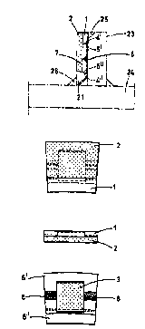
Figs . 1 (a) - (d) are a side view, top plan view, end
view and bottom plan view respectively of a wear element
according to the invention,
Figs. 2 (a) - (c) are a side view, plan view and end
view respectively of a wear plate to be used in the wear
element according to the invention,
Figs. 3 (a) - (c) are a sectional view, plan view and
end view respectively of a bracket f or holding the wear
plate of f ig . 2, and
Fig . 4 is a plan view of a slightly modif ied embodi-
ment of the bracket of fig. 2.
The wear element shown on fig. 1 consists of a wear
plate 2 of a hard material such as ceramics, rigidly locked
in a dovetail recess formed in a bracket 1 made of steel.
2s As best shown in fig. 2 the wear plate 2 includes a
trapezoidal body portion 9 with an unbroken wear surface 10
and a back portion 3 opposite the wear surface lO. The
back portion 3 is shown as a rectangular, preferably sub-
stantially square protrution of a smaller size than body
portion 9 and formed with opposite, inclined wedge surfaces
4 ', 4 ' ' for engaging complementary inclined wedge surfaces
of the bracket recess, and parallel straight (i.e. substan-
tially normal to the wear surface) side surfaces 2 . The
body portion 9 advantageously has a slightly curved front
3s edge 13 of a curvature adapted to the screw rim to which
the wear assembly is to be mounted, and slightly rearwardly
converging side edges 14 for engaging a side edge of adja-
.... . . ,, ,,,, ,, , _ A~EN~ED SH~Er

2 1 &1 7 1 8
cent wear elements upon mounting onto the scrQw rim. In
the example shown the one wedge surface 4 ' of the back
portion and two side surfaces 12 thereof are offset rela-
tive to the front edge 13 and two side edges 14 respec-
s tiveiy of the body portion 9, while the second wedge sur-
face 4 ' ' of the back portion alignes rhrith a correspondingly
inclined rear edge 15 of the body portion 9.
Preferably, the ~r2cket 1 is made of stainless steel.
As shQwn in fig. 3, according to an important feature of
the invention, it is initially formed in two separate parts
6 ' and 6 ' ', adapted t~ be welded together around the back
portion 3 of the wear ~late 2. In the example shown the
bracket 1, like the wear plate 2, is a substantially trape-
zoidal plate having a curved front edge 16 and converging
side edges 17 which, upon assembly, generally coincide -hrith
the front edge 13 and side edges 14 respectively of the
wear plate .
Each bracket part 6 ', 6 ' ' is provided with a channel-
like indentation 19 ', 19 ' ~ which, in the assembled (but yet
not welded) state of the bracket parts shown in f ig . 3,
- together form a substantially s~uare recess or opening 20
formed as a dovetail slit having opposite inclined wedge
surfaces 5', 5~ ~ respectively corresponding to the wedge
surfaces 4 ', 4 ' ' of the wear plate back portion 3 and
2s having straight end surfacas 18 corresponding to the
straight side surfaces 12 of the back portion. Thus, the
bottom surface of the indentations 19 ', 19 ' ~ of the bracket
parts 6 ', 6 ' ' respectively each form one of the wedge sur-
faces 5 ', j ' ' of the dovetail recess 2Q .
The wear element according to the invention as shorv-n
in fig. 1 is implemented by positioning the two separate
bracket parts 6 ~, 6 ~ ~ with their respective wedge surfaces
5 ~, 5 ' ~ tightly pressed against a respective wedge surface
4 ~, 4 ' ~ of the wear plate back portion 3, and then welding
3s the two bracket parts 6 ', 6 ' ' together along a welding
groove 8 which, in the example shown in figs. 1 and 3
extends on either side of the recess 20 along a line paral-
A~l~Nrùr-~ SltEEl

2 1 8 1 7 1 8 . -
lel to and pref erably substantially centrally between thewedge surfaces 5 ', S ' ' . As a result the wear plate will be
immovably locked between the wedge surfaces 5', 5 ' ' and end
surfaces 18 of the bracket parts. Preferably, to further
s strengthen the relative immobility of the wear plate and
bracket, an adhesive 7 may be applied at least between the
bottom surface of the wear plate body portion 9 and top
surface of bracket 1.
Advantageously, as sho~n in figs. 1 and 3, one of the
o brackets 6~ ' may have a thickened end portion 21 with a
shoulder 22 aligned with the bracket wedge surface S' ' to
engage a rear surface 15 of the wear plate body portion 4
aligned with the wedge surface 4 ' ' of the wear plate back
portion 3, for providing additional support to the wear
plate.
Fig. 1 (a) also illustrates how wear elements of the _
invention can be welded to the screw wing 23 of a scre~ 24
shown in phantom, by front weld 25 and rear weld 26.
The bracket lO1 shown in fig. 4 differs from bracket 1
20 of fig. 3, only by the welding grooves 108 formed by ~he
assembled bracket parts 106 ~, 106 ' ' extending normal rather
than parallel to the bracket top and bottom surf aces on
each side thereof.
Ah~END~D SHEEr

Representative Drawing
A single figure which represents the drawing illustrating the invention.
Administrative Status

2024-08-01:As part of the Next Generation Patents (NGP) transition, the Canadian Patents Database (CPD) now contains a more detailed Event History, which replicates the Event Log of our new back-office solution.

Please note that "Inactive:" events refers to events no longer in use in our new back-office solution.

For a clearer understanding of the status of the application/patent presented on this page, the site Disclaimer , as well as the definitions for Patent , Event History , Maintenance Fee  and Payment History  should be consulted.

Event History

Description Date
Inactive: IPC from MCD 2006-03-12
Application Not Reinstated by Deadline 2004-02-02
Time Limit for Reversal Expired 2004-02-02
Inactive: Abandoned - No reply to s.30(2) Rules requisition 2003-04-28
Deemed Abandoned - Failure to Respond to Maintenance Fee Notice 2003-01-31
Inactive: S.30(2) Rules - Examiner requisition 2002-10-28
Inactive: Entity size changed 2002-01-18
Letter Sent 1999-07-07
Inactive: Status info is complete as of Log entry date 1999-07-05
Inactive: Application prosecuted on TS as of Log entry date 1999-07-05
All Requirements for Examination Determined Compliant 1999-06-03
Request for Examination Requirements Determined Compliant 1999-06-03
Application Published (Open to Public Inspection) 1995-08-10

Abandonment History

Abandonment Date Reason Reinstatement Date
2003-01-31

Maintenance Fee

The last payment was received on 2002-01-07

Note : If the full payment has not been received on or before the date indicated, a further fee may be required which may be one of the following

  • the reinstatement fee;
  • the late payment fee; or
  • additional fee to reverse deemed expiry.

Patent fees are adjusted on the 1st of January every year. The amounts above are the current amounts if received by December 31 of the current year.
Please refer to the CIPO Patent Fees web page to see all current fee amounts.

Fee History

Fee Type Anniversary Year Due Date Paid Date
MF (application, 3rd anniv.) - small 03 1998-02-02 1997-12-23
MF (application, 4th anniv.) - small 04 1999-02-01 1998-12-21
Request for examination - small 1999-06-03
MF (application, 5th anniv.) - small 05 2000-01-31 2000-01-06
MF (application, 6th anniv.) - small 06 2001-01-31 2001-01-09
MF (application, 7th anniv.) - standard 07 2002-01-31 2002-01-07
Owners on Record

Note: Records showing the ownership history in alphabetical order.

Current Owners on Record
DAG OMMUNDSEN
Past Owners on Record
None
Past Owners that do not appear in the "Owners on Record" listing will appear in other documentation within the application.
Documents

To view selected files, please enter reCAPTCHA code :


To view images, click a link in the Document Description column. To download the documents, select one or more checkboxes in the first column and then click the "Download Selected in PDF format (Zip Archive)" or the "Download Selected as Single PDF" button.

List of published and non-published patent-specific documents on the CPD .

If you have any difficulty accessing content, you can call the Client Service Centre at 1-866-997-1936 or send them an e-mail at CIPO Client Service Centre.


Document
Description 
Date
(yyyy-mm-dd) 
Number of pages   Size of Image (KB) 
Representative drawing 1997-07-06 1 6
Abstract 1995-08-09 1 40
Description 1995-08-09 5 236
Drawings 1995-08-09 3 34
Claims 1995-08-09 2 62
Description 1999-07-28 5 241
Claims 1999-07-28 2 61
Acknowledgement of Request for Examination 1999-07-06 1 179
Courtesy - Abandonment Letter (Maintenance Fee) 2003-03-02 1 178
Courtesy - Abandonment Letter (R30(2)) 2003-07-06 1 165
PCT 1996-07-18 13 481
Fees 1997-01-09 1 51