Note: Descriptions are shown in the official language in which they were submitted.
- 2182~41
WEDGE CONNECTOR FOR ELECTRICAL CONDUCTORS
CROSS-REFERENCE TO RELATED APPLICATION
.
This is a continuation-in-part application of U.S.
application No. 08/306,463 filed 9/15/94.
BACKGROUND OF THE INVENTION
1. Field of the Invention
The present invention relates to electrical connectors and,
more particularly, to a wedge connector.
2. Prior Art
U.S. Patent 4,650,273 discloses an electrical connector
with a general "C" shaped sleeve and a wedge. The wedge is
stamped and formed from sheet metal and has a tab at its
front end. The tab engages a front end of the sleeve to
resist withdrawal of the wedge from the sleeve. U.S.
Patent 5,006,081 discloses a wedge connector with a "C"
shaped sleeve having a hole in its middle section for
engaging a dimple on a stamped and formed sheet metal
wedge. Other U.S. Patents that relate to wedge connectors
include the following:
2,106,724 2,814,025
2,828,147 3,065,449
3,275,974 3,329,928
3,349,167 3,462,543
~ 3,504,332 3,516,050
3,588,791 3,920,310
4,059,333 4,533,205
4,600,264 4,634,205
4,723,920 4,723,921
4,730,087 4,734,062
21824~1
-
4,813,894 4,863,403
4,872,856 4,915,653
5,044,996 5,145,420
5,244,422
S SUMMARY OF THE INVENTION
In accordance with one embodiment of the present invention
an electrical connector is provided for connecting
electrical conductors. The connector comprises a connector
sleeve and a wedge. The sleeve has a general "C" shape.
The wedge is adapted to be located inside the sleeve and
comprises a sheet metal member having an elongate length
that is folded over itself lengthwise to form the wedge.
The wedge has multiple latching ledges on a lateral side of
the wedge formed by a side edge of the sheet metal member.
-: .
In accordance with another emboA;m~nt of the present
invention an electrical connector is provided for
connecting electrical conductors together. The connector
comprises a one piece connector sleeve and a wedge. The
connector sleeve has a general "C" shape formed by two
opposing ~hAnnPl sections interconnected by a middle
section. The middle section has a stop ledge and a
longitll~; n~l depression along an interior side of the
middle section. The wedge is suitably sized and shaped to
be inserted in the sleeve. The wedge has multiple latching
ledges on a lateral side of the wedge for engaging the stop
ledge to prevent the wedge from being l~llloved from the
sleeve.
In accordance with another embodiment of the present
invention in an electrical connector having a sleeve and a
wedge for use in connecting electrical conductors together,
the wedge being comprised of a single sheet metal member
that has been deformed into the wedge shape, the
-- l .
2182~41
.~ .
improvement comprises the sheet metal member having an
elongate length which is folded over itself at least two
times along its length to form the length of the wedge and
multiple latching ledges on a lateral side.
BRIEF DESCRIPTION OF THE DRAWINGS
The foregoing aspects and other features of the present
invention are explained in the following description, taken
in connection with the accompanying drawings, wherein:
Fig. 1 is a perspective view of a wedge of an electrical
wedge connector incorporating features of the present
invention;
Fig. 2 is a perspective view of a sleeve of an electrical
wedge connector for use with the wedge shown in Fig. l; and
Fig. 3 is a cross-sectional view of the wedge and sleeve
shown in Figs. 1 and 2 at a partially assembled position.
DETAILED DESCRiPTION OF THE PREFERRED EMBODIMENTS
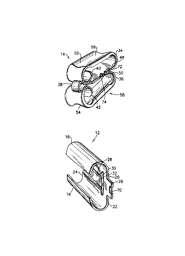
Referring to Figs. 1-3, there is shown a wedge 14 and
sleeve 12 incorporating features of the present invention.
The wedge 14 and sleeve 12 form a wedge connector 10 (see
Fig. 3) for connecting two electrical conductors (not
shown) together. Although the present invention will be
described with reference to the single embodiment shown in
the drawings, it should be understood that the present
invention can be embodied in many alternate embodiments.
In addition, any suitable size, shape or type of elements
or materials could be used.
The sleeve 12 is preferably made of sheet metal, but it
could also be a cast, drawn, or extruded member. The
~182~ ll
sleeve 12 has two opposing channel sections 16, 18
interconnected by a middle section 20 to form a general "C"
shape. The "C" shape tapers from the rear end 22 to the
- front end 24. The middle section 20 includes a rear end
S tab 26, a groove or depression 28, and a slot 30. The slot
30 is located proximate the rear end of the sleeve and
forms a stop ledge 32. The slot 30 extends entirely through
the middle section 20 from the interior surface to the
exterior surface. However, in an alternate embodiment that
slot 30 need not extend entirely through the middle section
20. The depression 28 extends from the slot 30 to the
front end 24 of the sleeve. In another alternate
embodiment, the depression 28 need not extend to the front
end 24, but the slot 30 should be located at the rear end
of the depression 28.
The wedge 14 is comprised of a single elongate sheet metal
member that has been deformed into the shape shown. The
sheet metal member has been folded over itself in a
lengthwise direction several times along its length to form
the wedge 14. In alternate embodiments, more or less folds
could be provided. The wedge 14 has two adjacent main loop
sections 34, 36 interconnected by a third loop section 38.
The two longit~ l ends 40, 42 of the sheet metal member
- are located in the two main loops 34, 36, respectively.
The third loop 38, in addition to interconnecting the first
and second main loops 34, 36 also functions as a back
support or containment support for the main loops 34, 36.
Because of the curved nature of the third loop 38, when the
wedge is compressed, the ends 40, 42 can be rotated towards
the inside surfaces of the main loops 34, 36. If the
compressive force is sufficient enough, the ends 40, 42 can
contact the inside surfaces of the main loops 34, 36 to add
rigidity to the main loops. The backsides 48, 50 of the
main loops 34, 36 are located adjacent each other. The
exterior sides 52, 54 of the main loops 34, 36 have grooves
56, 58 for locating the conductors in. In the embodiment
shown, the depth of the groove 56 in the first main loop 34
21824~1
is greater than the depth of the groove 58 in the second
main loop 36 for accomm~dating a larger conductor.
However, any type of suitable shapes could be provided on
the exterior sides 52, 54.
S One of the lateral sides of the wedge 14 has a full
insertion latching ledge 60. More specifically, the
lateral side 62 of the backsides 48, 50 progressively
extend in a lateral direction from the front to the rear
which then form the ledge 60 just before the third loop 38.
The side 62, thus, forms a ramp in front of the latching
ledge 60. The latching ledge 60 is adapted to be located
in the slot 30 of the connector sleeve 12 to prevent the
wedge 14 from being inadvertently disengaged from the
sleeve 12. The ramp formed by the lateral side 62 of the
backsides 48, 50 is provided to ease insertion of the wedge
14 into the sleeve 12 over the section of the sleeve rear
of the stop ledge 32. The interior longitudinal depression
28 on the middle section 20 of the sleeve 12 is provided in
front of slot 30 to accommodate the lateral side ramp of
the wedge 14. When the connector 10 connects the two
conductors the latching ledge 60 is located in the slot 30
such that the stop ledge 32 can engage the latching ledge
60 to prevent unintentional removal of the wedge 14 from
inside the sleeve 12. However, the slot 30 nonetheless
allows a user access to the side 62 if it is desired to
intentionally remove the wedge 14 from the sleeve 12.
In addition to the full insertion latching provided by the
ledges 32 and 60, the connector 10 also has a temporary
intermediate latching system. More specifically, the
sleeve 12 has an inwardly protruding bump or tab 70 at the
rear end tab 26, and the wedge 14 has cutouts 72, 74 in the
backsides 48, 50 at the lateral side 62. The cutouts 72,
74 are located in front of the full insertion ledge 60.
With this system the wedge 14 can be partially inserted
into the sleeve 12 and latched together. During insertion
of the wedge 14 into the sleeve 12 the backsides 48, 50 are
2182441
-
c~mme~ in direction A until the first cutout 72 comes into
registry with the inwardly protruding tab 70. The
backsides 48, 50 then snap back in direction B to
temporarily latch the wedge and sleeve together. This
allows the conductors, wedge, and sleeve to the properly
positioned relative to each other and form an ~ss~mhly that
is held together while a tool (not shown) for fully
inserting the wedge into the sleeve is attached to the
assembly. If the conductors are small, the user can move
the lateral side 62 in direction A to disengage the
inwardly protruding tab 70 from the first cutout 72. The
wedge 14 would then be moved forward in the sleeve 12 and
the third loop 38 released with the inwardly projecting tab
70 being received in the second cutout 74. Thus, the wedge
14 can be received at either of the two intermediate
positions. Each cutout 72, 74 has a general "V" shape.
The front side of the "V" shape forms a ledge for
interacting with the front of the inwardly projecting bump
or tab 70 to prevent the wedge 14 from coming out of the
sleeve 12. The rear side of the "V" shape and the sloped
rear of the tab 70 form c~mm;ng surfaces to cam the lateral
side in direction A when the tool (not shown) propels the
wedge 14 into its fully inserted position. The backsides
48, 50 snap back in direction B when the full insertion
ledge 60 passes the inwardly projecting tab 70. The fully
inserted position is when the ledge 60 engages with the
ledge 32.
It should be understood that the foregoing description is
only illustrative of the invention. Various alternatives
and modifications can be devised by those skilled in the
art without departing from the spirit of the invention.
Accordingly, the present invention is intended to em~brace
all such alternatives, modifications and variances which
fall within the scope of the appended claims.