Language selection

Search

Patent 2182538 Summary

Third-party information liability

Some of the information on this Web page has been provided by external sources. The Government of Canada is not responsible for the accuracy, reliability or currency of the information supplied by external sources. Users wishing to rely upon this information should consult directly with the source of the information. Content provided by external sources is not subject to official languages, privacy and accessibility requirements.

Claims and Abstract availability

Any discrepancies in the text and image of the Claims and Abstract are due to differing posting times. Text of the Claims and Abstract are posted:

  • At the time the application is open to public inspection;
  • At the time of issue of the patent (grant).
(12) Patent: (11) CA 2182538
(54) English Title: TIMER CONTROLLED OUTDOOR GROUND LIGHTING SYSTEM WITH INTRUDER DETECTION
(54) French Title: SYSTEME D'ECLAIRAGE ANTI-INTRUSION COMMANDE PAR UNE MINUTERIE ELECTRIQUE
Status: Term Expired - Post Grant Beyond Limit
Bibliographic Data
(51) International Patent Classification (IPC):
  • H05B 47/115 (2020.01)
(72) Inventors :
  • MACKAY, IAIN N. B. (Canada)
(73) Owners :
  • NII NORTHERN INTERNATIONAL INC.
(71) Applicants :
  • NII NORTHERN INTERNATIONAL INC. (Canada)
(74) Agent: PERLEY-ROBERTSON, HILL & MCDOUGALL LLP
(74) Associate agent:
(45) Issued: 2001-06-19
(22) Filed Date: 1996-08-01
(41) Open to Public Inspection: 1997-02-18
Examination requested: 2000-07-12
Availability of licence: N/A
Dedicated to the Public: N/A
(25) Language of filing: English

Patent Cooperation Treaty (PCT): No

(30) Application Priority Data:
Application No. Country/Territory Date
08/516,191 (United States of America) 1995-08-17

Abstracts

English Abstract

An outdoor ground lighting system that includes one or more low voltage lamp units, provided from a step down transformer connectable to a high voltage AC power supply, and an on/off timer operative to turn the lamps on for a selected time period during hours of darkness. Added to this known system is a secondary low voltage switching system that includes a solenoid operated normally open switch in which the switch is shunted across the timer controlled switch. A detector detects the presence of a person or the like in the field of view of the detector and provides an output signal in response thereto. The signal activates the solenoid thereby closing the switch to turn on the lamps when the timer is in the off cycle. The secondary switching system enhances the garden lighting system by providing a security lighting system when the timer is in an off mode.


French Abstract

Un système d'éclairage extérieur comprenant une ou plusieurs lampes basse tension, fourni à partir d'un transformateur abaisseur de tension pouvant être connecté à une alimentation CA haute tension, et une minuterie de marche/d'arrêt fonctionnelle pour allumer les lampes pendant une durée sélectionnée lorsqu'il fait sombre. Un système de commutation basse tension secondaire, comprenant un commutateur normalement ouvert actionné par solénoïde où le commutateur est aiguillé à travers le commutateur contrôlé par la minuterie, est ajouté à ce système connu. Un détecteur détecte la présence d'une personne ou d'un être similaire dans le champ de vision du détecteur et fournit, en réponse, un signal de sortie. Le signal active le solénoïde, fermant ainsi le commutateur afin d'allumer les lampes lorsque la minuterie est désactivée. Le système de commutation secondaire améliore le système d'éclairage de jardin en offrant un système d'éclairage sûr lorsque la minuterie est en mode désactivé.

Claims

Note: Claims are shown in the official language in which they were submitted.

-7-
THE EMBODIMENTS OF THE INVENTION IN WHICH AN EXCLUSIVE
PROPERTY OR PRIVILEGE IS CLAIMED ARE DEFINED AS FOLLOWS:
1. An outdoor yard lighting system comprising a plurality of
low voltage lamp units, a first step down transformer means for
supplying said lamp units with low voltage from a common
residential high AC voltage supply, timer controlled switch means
in the high voltage circuit connected to said first step down
transformer means and operable to turn the lamp units on and off
for selected periods of time and a secondary switching system
having a normally open switch shunted across said timer controlled
switch means, detector means to detect the presence of an intruder
in a selected area, said detector means providing an output signal
upon detection of the intruder in said selected area, said
secondary switching system comprising a second step down
transformer with a high voltage side thereof connected to said AC
voltage supply and circuit means and a relay connected to a low
voltage side of said second step down transformer to close said
normally open switch in response to an output signal from said
detector means.
2. An improved outdoor ground lighting system that includes
at least one lamp unit, a first step down transformer connectable
to a high voltage AC power supply to provide a low voltage supply
for the lamp of said lamp unit, and an on/off timer operative to
turn the lamp on for a selected time period during hours of
darkness, the improvement comprising detector means to detect the
presence of a person in the field of view of the detector and
provide an output signal in response to such detection and a
secondary switching system operatively responsive to said output
signal to switch on said lamp when said timer is in the off cycle,

-8-
said timer controlling an on/off switch to the high voltage side
of said first transformer and wherein said secondary switching
system includes a second step down transformer and a relay operated
normally open switch, said normally open switch being shunted
across said timer controlled on/off switch, said relay of said
normally open switch being connected to a low voltage side of said
second transformer and wherein said detector output signal is
operatively associated with said relay to close said normally open
switch in response to an output signal from the detector.
3. An improved outdoor ground lighting system as defined in
claim 2, including a system control housing and wherein said step
down transformers, timer and secondary switching system are mounted
in said housing.

Description

Note: Descriptions are shown in the official language in which they were submitted.


21g~5~
-- 1 --
Title
TIMER CONTROLLED OUTDOOR GROUND LIGHTING SYSTEM WITH
INTRUDER DETECTION
Field of the Inven~ion
The present invention relates generally to timer
controlled outdoor ground lighting systems and more particularly
to enhancement o~ such systems to turn on the lamps of the 6ystem
when in the of f cycle of operation and upon detection of the
pre6ence of a human being or the like warm blooded animal.
10 33ackcrround of InventiQn
outdoor ground lighting systems are in common use for
aesthetic purposes around residences and many are timer controlled
to be on for selected periods of time during hours of darkness.
The lamps of the outdoor lighting units operate at low voltage
15 converted by suitable means such as transformers from the normal
120VAC or 240VAC power supply. These known outdoor lighting
~;y6tems also provide a certain element of security by illuminating
dark areas during the selected period of time, but not thereafter.
In addition to outdoor lighting systems, many households
20 further have intruder detection systems that illuminate a selected
area upon detection of an intruder. The sensors are normally
passive infrared detectors (]?ID). These thermal electric infrared
optical sensors provide a signal to turn on the lights upon
detection of an intruder in a known manner.
25 SummarY of the Invention
A principle object of the present invention is to provide

~ ~ 82~38
-- 2 --
enhancement of outdoor ground lighting systems so that they
operate, during an off period, as a security lighting system to
illuminate the area in which they are located upon detection of an
intruder .
In accordance with the present invention there is
particularly provided improvements in an outdoor ground lighting
system that includes at least one lamp unit, a step down
transformer or the like to provide a low voltage supply for the
lamp of said lamp unit, and an on/off timer operative to turn the
lights on for selected time periods during hours of ~rkn~, the
illlpL ~V. -nt comprising a secondary switching system having a
normally open switch shunted across the timer controlled switch
which is in the circuit of the high voltage supply to said step
down transf ormer and detector means to detect the presence of an
intruder, said secondary switching system including a second step
down transformer with circuit means operative in response to an
output signal from said detector means resulting from the presence
of a person or the like i~truder in the f ield of view of the
detector that scans said selected area to switch on said lamps when
said timer is in the off cycle. The detector means may be a motion
sensor, a sound activated sensor or a heat sensor, i.e. a passive
infrared detector.
Brief Description of the Drawinqs
~he invention is illustrated by way of example in the
accompanying drawings wherein:
Figure 1 is a diagrammatic view of a decorative ground
lighting system and schematic of the step ~own transformer timer
and secondary switching theref ore, the latter }~eing provided in

_ 3 _ 2~2~
accordance with the present invention; and
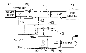
Figure 2 is a circuit diagram for the ground lighting
system of Figure 1 incorporating a secondary switching 6ystem to
bypass the timing device.
5 Description of Preferred rm~odit-nt
Referring to the drawing, there is diagrammatically
illustrated in Figure 1 a decorative garden lighting system that
includes a number of spaced apart lamp units or fixtures 11 located
in a garden area to illuminate the same during selected periods of
10 darkness and a control unit 12.
The control unit 12 includes a timer 30 for selecting
on/off periods of operation and a step down transformer TR1 to
provide low voltage to the lamps via output line 0/P. An input
line 1/P plugs into a high voltage AC power supply of 120 or 240
15 volts. This is conventiona] in the art.
In accordance with the present invention, the above
3ystem i8 enhanced by providing means to bypass the timer and turn
on the lights during the timer off period when the presence of a
person or like warm blooded animal has been detected. The system
20 can be used to illuminate a walkway facilitating entry of an
occupant's late arrival into his own residence or act as a security
measure against intruders.
The system enhancement means includes a detector 40 and
circuitry in a unit 50 lo~ated in the control unit 12. The
25 detector 40 may for example be a thermo electric infrared optical
sensor also referred to as a passive infrared detector (PID) and
is suitably mounted and located to provide a field of view of the
desired area. In a prototype system applicant used a detector

~ - 4 - 2~8~S3~
model NW-12 from Apek Secure I,ite Co. IJtd. located in Taiwan. The
detector 40 can be mounted on one of the lamp units 11 or mounted
as a separate unit at a suitable location. A sensor activated by
sound or motion sensor could be used in place of or in addition to
5 the infrared sensor.
The circuitry of unit 50 consists of a second step down
transformer TR2, a resistor R1, a diode Dl, a capacitor Cl and a
relay RI. The transformer TR2 transforms the 120 tor 240) VAC
supply to 12 (or 24) VAC. I~esistor Rl, diode D1 and capacitor Cl
rectify this voltage which supplies the sensor 40 with 12 or 24
volt DC as the case may be. This voltage i5 i601ated from the main
power line by the transformer TR2 and is inherently safe from major
shocks. In applicant's prototype transformer TR2 functionally
replaced the transformer in the above mentioned detector NW-12.
The sensor 40 upon detecting the presence of a human or
animal, provides an output signal that causes activation of the
relay RI causing contacts RIC to close. The contacts are a
normally open switch in the circuit of leads Ll and L2 that are
connected to line L3 of the supply to bypass the on/off contacts
20 of timer 30. The lights th~s turn on during the off cycle of the
timer when the sensor 40 detects the presence of a person, animal
or the like or a moving object in the case of a motion sensor.
The transformer TR2, resistor Rl, diode Dl, capacitor Cl
and the relay RI are a separate potted unit located in the housing
25 of the control unit as is illustrated in Figure 1 and mentioned
above. A separate plug 60 and cable 61 connect to the control unit
and carry the low voltage to the sensor 40 together with the return
"on" signal to the relay.
The foregoing provides not only an ener~y saving "on/off"

2~ 8~$38
-- 5 --
aesthetic garden and/or walkway lighting system, but also one which
provides the dual function of security lighting of dark areas
during the off period of the system.
A conventional system with the timer set to turn the
lights on at 8:00 p.m. and off at 11:30 p.m. would leave the
homeowner returning at 1: 00 a.m. in the dark, but with the present
system, the sensor would detect the human presence and activate the
lighting system thus providing a safe lit area to the doorway.
A conventional system with the timer 6et to turn the
lights on at 8:00 p.m. and off at 11:30 p.m. provides illuminated
security only for those hours. With the present apparatus, the
sensor would activate the lighting system if an intruder should
attempt to take advantage of an unlit area.
However, because the present system allows both light
f ixtures and the secondary switching system to operate on low
voltage, the system now becomes far less expensive to install and
operate than a conventional 120V system. It also, because of low
voltage is not required to meet the same installation standards and
mandatory inspection that a 120V system is required to do. This
will enable the system to have many dedicated security functions
not incorporated with landscape lighting. For instance, an out
building not equipped with electrical power can be supplied with
low voltage lighting and a low voltage sensor to provide security
lighting or convenience lighting. To do this with conventional
120V power would require: (a) a permit; (b) cable buried 4 feet
below grade inside a conduit; (c) exterior wiring above ground
around the outbuilding protected by conduit; (d) final inspection
and approval.
With the low voltage system, there is no need to bury the

. ~ 2~ 82~8
-- 6 --
cable, place it in conduit, nor apply for permit or inspection.
The present invention involves two known arts. One, the
trans eormer control, the other, human presence detectors (passive
infrared, etc. ) and allows them to be combined in an uni~ue and
5 useful manner.

Representative Drawing
A single figure which represents the drawing illustrating the invention.
Administrative Status

2024-08-01:As part of the Next Generation Patents (NGP) transition, the Canadian Patents Database (CPD) now contains a more detailed Event History, which replicates the Event Log of our new back-office solution.

Please note that "Inactive:" events refers to events no longer in use in our new back-office solution.

For a clearer understanding of the status of the application/patent presented on this page, the site Disclaimer , as well as the definitions for Patent , Event History , Maintenance Fee  and Payment History  should be consulted.

Event History

Description Date
Inactive: IPC removed 2021-01-06
Inactive: First IPC assigned 2021-01-06
Inactive: IPC assigned 2021-01-06
Inactive: IPC expired 2020-01-01
Inactive: IPC removed 2019-12-31
Inactive: Expired (new Act pat) 2016-08-01
Small Entity Declaration Determined Compliant 2008-05-30
Small Entity Declaration Request Received 2008-05-30
Letter Sent 2001-11-08
Inactive: Multiple transfers 2001-10-01
Grant by Issuance 2001-06-19
Inactive: Cover page published 2001-06-18
Inactive: Final fee received 2001-03-06
Pre-grant 2001-03-06
Letter Sent 2000-09-27
Notice of Allowance is Issued 2000-09-27
Inactive: Approved for allowance (AFA) 2000-09-13
Amendment Received - Voluntary Amendment 2000-08-24
Inactive: S.30(2) Rules - Examiner requisition 2000-08-08
Inactive: Status info is complete as of Log entry date 2000-07-28
Letter Sent 2000-07-28
Inactive: Application prosecuted on TS as of Log entry date 2000-07-28
Request for Examination Requirements Determined Compliant 2000-07-12
All Requirements for Examination Determined Compliant 2000-07-12
Application Published (Open to Public Inspection) 1997-02-18
Small Entity Declaration Determined Compliant 1996-08-01

Abandonment History

There is no abandonment history.

Maintenance Fee

The last payment was received on 2000-07-12

Note : If the full payment has not been received on or before the date indicated, a further fee may be required which may be one of the following

  • the reinstatement fee;
  • the late payment fee; or
  • additional fee to reverse deemed expiry.

Please refer to the CIPO Patent Fees web page to see all current fee amounts.

Fee History

Fee Type Anniversary Year Due Date Paid Date
MF (application, 2nd anniv.) - small 02 1998-08-03 1998-07-14
MF (application, 3rd anniv.) - small 03 1999-08-02 1999-06-24
MF (application, 4th anniv.) - small 04 2000-08-01 2000-07-12
Request for examination - small 2000-07-12
Final fee - small 2001-03-06
MF (patent, 5th anniv.) - small 2001-08-01 2001-07-18
Registration of a document 2001-10-01
MF (patent, 6th anniv.) - small 2002-08-01 2002-05-08
MF (patent, 7th anniv.) - small 2003-08-01 2003-07-18
MF (patent, 8th anniv.) - small 2004-08-02 2004-06-03
MF (patent, 9th anniv.) - small 2005-08-01 2005-07-07
MF (patent, 10th anniv.) - small 2006-08-01 2006-06-12
MF (patent, 11th anniv.) - small 2007-08-01 2007-06-01
MF (patent, 12th anniv.) - small 2008-08-01 2008-05-30
MF (patent, 13th anniv.) - small 2009-08-03 2009-07-20
MF (patent, 14th anniv.) - small 2010-08-02 2010-06-01
MF (patent, 15th anniv.) - small 2011-08-01 2011-07-14
MF (patent, 16th anniv.) - small 2012-08-01 2012-06-08
MF (patent, 17th anniv.) - small 2013-08-01 2013-07-19
MF (patent, 18th anniv.) - small 2014-08-01 2014-07-23
MF (patent, 19th anniv.) - small 2015-08-03 2015-07-24
Owners on Record

Note: Records showing the ownership history in alphabetical order.

Current Owners on Record
NII NORTHERN INTERNATIONAL INC.
Past Owners on Record
IAIN N. B. MACKAY
Past Owners that do not appear in the "Owners on Record" listing will appear in other documentation within the application.
Documents

To view selected files, please enter reCAPTCHA code :


To view images, click a link in the Document Description column. To download the documents, select one or more checkboxes in the first column and then click the "Download Selected in PDF format (Zip Archive)" or the "Download Selected as Single PDF" button.

List of published and non-published patent-specific documents on the CPD .

If you have any difficulty accessing content, you can call the Client Service Centre at 1-866-997-1936 or send them an e-mail at CIPO Client Service Centre.


Document
Description 
Date
(yyyy-mm-dd) 
Number of pages   Size of Image (KB) 
Cover Page 1996-11-06 1 16
Abstract 1996-11-06 1 23
Description 1996-11-06 6 220
Claims 1996-11-06 3 111
Drawings 1996-11-06 1 21
Cover Page 2001-05-14 1 37
Drawings 2000-08-24 1 27
Claims 2000-08-24 2 75
Representative drawing 2001-05-14 1 7
Abstract 2001-06-18 1 23
Description 2001-06-18 6 220
Representative drawing 1997-07-23 1 12
Reminder of maintenance fee due 1998-04-02 1 111
Acknowledgement of Request for Examination 2000-07-28 1 177
Commissioner's Notice - Application Found Allowable 2000-09-27 1 163
Fees 2012-06-08 1 156
Fees 2003-07-18 1 27
Fees 2002-05-08 1 26
Fees 2001-07-18 1 25
Correspondence 2001-03-06 3 105
Fees 1998-07-14 1 44
Fees 1999-06-24 1 33
Fees 2000-07-12 2 54
Fees 2004-06-03 1 29
Fees 2005-07-07 1 27
Fees 2006-06-12 1 26
Fees 2007-06-01 1 26
Fees 2008-05-30 2 56
Correspondence 2008-05-30 2 56
Fees 2009-07-20 1 201
Fees 2010-06-01 1 201
Fees 2011-07-14 1 202
Fees 2013-07-19 1 24
Fees 2014-07-23 1 24
Fees 2015-07-24 1 26