Language selection

Search

Patent 2182606 Summary

Third-party information liability

Some of the information on this Web page has been provided by external sources. The Government of Canada is not responsible for the accuracy, reliability or currency of the information supplied by external sources. Users wishing to rely upon this information should consult directly with the source of the information. Content provided by external sources is not subject to official languages, privacy and accessibility requirements.

Claims and Abstract availability

Any discrepancies in the text and image of the Claims and Abstract are due to differing posting times. Text of the Claims and Abstract are posted:

  • At the time the application is open to public inspection;
  • At the time of issue of the patent (grant).
(12) Patent Application: (11) CA 2182606
(54) English Title: CONTROL AND CLOSURE DEVICE FOR A METALLURGICAL VESSEL
(54) French Title: DISPOSITIF DE REGLAGE ET DE FERMETURE POUR UN RECIPIENT METALLURGIQUE
Status: Deemed Abandoned and Beyond the Period of Reinstatement - Pending Response to Notice of Disregarded Communication
Bibliographic Data
(51) International Patent Classification (IPC):
  • B22D 41/14 (2006.01)
  • B22D 39/00 (2006.01)
  • B22D 41/60 (2006.01)
(72) Inventors :
  • BRUCKNER, RAIMUND (Germany)
  • ARDELL, RICK (United States of America)
  • SCHIEFER, BERNHARD (United States of America)
(73) Owners :
  • DIDIER-WERKE AG
(71) Applicants :
  • DIDIER-WERKE AG (Germany)
(74) Agent: SMART & BIGGAR LP
(74) Associate agent:
(45) Issued:
(86) PCT Filing Date: 1995-11-25
(87) Open to Public Inspection: 1996-07-11
Availability of licence: N/A
Dedicated to the Public: N/A
(25) Language of filing: English

Patent Cooperation Treaty (PCT): Yes
(86) PCT Filing Number: PCT/EP1995/004649
(87) International Publication Number: EP1995004649
(85) National Entry: 1996-08-01

(30) Application Priority Data:
Application No. Country/Territory Date
195 00 012.9 (Germany) 1995-01-02

Abstracts

English Abstract


A regulating and closing device for a metallurgical
vessel, having a rotor that is used to throttle or shut off
the flow of smelt which is supported so as to be rotatable
within a stator (1) that is arranged within a wall of the
vessel (2). This allows heating of the rotor (4) which is
surrounded by an inductor (11) or direct heating of the smelt
by coupling the smelt in the flow to the field of said
inductor (11) electromagnetically.


French Abstract

La présente invention concerne un dispositif de réglage et de fermeture d'un récipient métallurgique. Dans un stator (1) logé dans une paroi (2) du récipient, un rotor (4) est monté de façon à pouvoir tourner, pour réduire ou arrêter le passage de la coulée. Une possibilité de chauffage y est intégrée du fait que le rotor (4) est entouré d'un inducteur (11) au champ duquel la coulée, dans le conduit de passage (6), ou le rotor (4), peuvent être couplés électromagnétiquement.

Claims

Note: Claims are shown in the official language in which they were submitted.

THE EMBODIMENTS OF THE INVENTION IN WHICH AN EXCLUSIVE
PROPERTY OR PRIVILEGE IS CLAIMED ARE DEFINED AS FOLLOWS:
1. A device for installation in a metallurgical vessel
to control a flow of smelt, comprising:
a stator, a rotor, the stator having a flow passage
for communication with the interior of the vessel and the
rotor having a flow passage for communication with the exterior
of the vessel, said rotor being rotatable to align said flow
passages to allow the flow of smelt therethrough, and an
inductor which surrounds said rotor, the inductor being
operative to generate an electromagnetic field to induce heat-
ing of the smelt within said passages.
2. A device as defined in claim 1, wherein the inductor
is arranged within the vessel wall or within the stator.
3. A device as defined in claim 1 or claim 2, wherein
the rotor is of a refractory ceramic material that is
electrically conductive so that the rotor, but not the smelt,
is heated by the electromagnetic field of the inductor, the
rotor transferring heat to the smelt by thermal transfer.
4. A device as defined in claim 3, wherein the
refractory ceramic material is a resin bonded highly aluminous
material.
5. A device as defined in claim 1 or 2, wherein the
rotor is of a refractory ceramic material so that the smelt
- 7 -

but not the rotor is heated by the electromagnetic field.
6. A device as defined in claim 1, 2 or 5, wherein a
central displacement body is arranged within the flow channel
which assists regulation of the flow of the smelt that is
exposed to the electromagnetic field of the inductor.
- 8 -

Description

Note: Descriptions are shown in the official language in which they were submitted.


'~1 8~6~J6
A REGULATING AND CLOSING DEVICE FOR
A METALLURGICAL VESSEL
The present invention relates to a regulating and
closing device for a metallurgical vessel.
EP 0 361 052 Bl describes such a device in which a
rotor is so arranged as to be able to rotate within a stator
installed in the wall of the vessel; both the rotor and the
stator incorporate flow passages that can be aligned with
each other by rotation, there being a flow channel for the
cmelt within the rotor. No provision is made for heating the
smelt in the vicinity of the device. In extreme cases, at
some locations the smelt can reach a temperature that is too
low for unimpeded operation. For example, the smelt can
solidify between sealing surfaces in the vicinity of the flow
passages.
DE 44 05 082 Al describes an electromagnetic flow
regulator (EFR) with a nozzle in combination with an
inlet/outlet valve, namely a slide gate. Since the nozzle is
of material that is electrically non-conductive, the smelt
that is in the nozzle couples to the electromagnetic field of
the coil, but the nozzle itself does not. Within the slide
gate, the electromagnetic field is meant to couple to the smelt
that may have hardened there in order to melt it. Because the
slide gate is a long way outside the field of the coil, this
is difficult to achieve, and at best can only be achieved
after a long delay.
-- 1 --
23843-246

2~ 82606
Coupling the smelt in order to regulate the flow
increases the temperature of the smelt. However, throttling
the flow of smelt independently of the smelt being heated is
not possible.
It is the task of the present invention to propose
a regulating and closing device of the general type described
in the introduction, in which throttling or regulation, and
shutting off a flow of smelt from a vessel is integrated with
the possibility of heating the smelt. It is preferred that
heating be effected independently of the regulating and shut-
off function.
The present invention provides a device for
installation in a metallurgical vessel to control a flow of
smelt, comprising: a stator, a rotor, the stator having a
flow passage for communication with the interior of the vessel
and the rotor having a flow passage for communication with the
exterior of the vessel, said rotor being rotatable to align
said flow passages to allow the flow of smelt therethrough,
and an inductor which surrounds said rotor, the inductor being
operative to generate an electromagnetic field to induce
heating of the smelt within said passages.
Using this device means that the flow of smelt can
be throttled or shut off by rotating the rotor, and the smelt
can also be heated. Hence, the smelt should not freeze, but
should the smelt freeze it can be melted or, if necessary,
reheated.
23843-2~6

.
6 0 6
If the rotor is coupled to the electromagnetic
field, the smelt is heated by thermal transfer from the rotor.
Throttling and closing are effected independently of heating,
by rotating the rotor.
If the smelt itself is coupled to the electro-
magnetic field, then it is heated directly. Closing can be
effected independently of heating by rotation of the rotor.
A throttling function results from the effect of ~he electro-
magnetic field, and this can be augmented by a displacement
body in the flow passage. In addition, the flow of smelt can
also be controlled by rotation of the rotor.
The appended drawings show embodiments of the
invention by non-limiting examples.
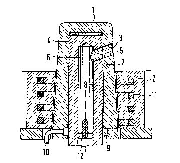
Figure 1: A regulating and closing device on a
metallurgical vessel, shown in cross-sectiGn~
Figure 2: A view that corresponds to Figure 1,
showing an additional embodiment.
A stator (1) that is of refractory ceramic material,
is installed in the bottom (2) of a metallurgical vessel. The
stator (1) has at least one flow aperture (3) at the side, and
this opens out into the interior of the vessel. A hollow,
cylindrical rotor (4) is arranged within the stator (1) in
such a way that it can rotate about a vertical axis (A). The
rotor (4) incorporates at least one flow opening (5) that
corresponds to the flow opening (3), and this opens out into
a coaxial flow channel (6) within the rotor (4).
23843-246

21 82606
There are cylindrical sealing surfaces (7) between
the stator (1) and the rotor (4), around the flow passages
(3, 5). Beneath the sealing surfaces (7) there is a space (8)
that opens out into an annular gap (9) into which inert gas
can be injected through a line (10).
The flow openings (3, 5) can be brought more or less
into alignments by rotating the rotor (4) within the stator
(l); this means that the flow of the smelt from the interior
of the vessel into the flow channel (6) can be throttled more
or less and interrupted.
The rotor (4) is enclosed by an inductor (11) that
is formed from a cooled electromagnetic coil. In the embodi-
ments, the inductor (11) is incorporated into the bottom (2)
of the vessel that can incorporate a special perforated brick
for this purpose. However, it is also possible to arrange the
inductor (11) within the stator (1). In both of the embodi-
ments, the stator (1) consists of a refractory ceramic
material that is not electrically conductive.
In the embodiment that is shown in Figure 1, the
rotor (4) is of a refractory ceramic material that is
electrically conductive, for example, a resin-bonded material
that contains highly aluminous material. The rotor (4) but,
however, not -- or only to an insignificant degree -- the
smelt that is flowing through the flow channel (6), is coupled
to the electromagnetic field of the inductor (11).
The embodiment that is shown in Figure 1 works as
follows:
-- 4
23843-246

21 82606
In order to throttle or shut off the flow of smelt,
the rotor (4) is rotated about the axis (A). Independently
the temperature of the smelt can also be changed. To change
the temperature of the smelt, the inductor (11) is switched on,
thereby heating the rotor (4). The heat of the rotor (4)
passes by thermal conductivity and/or thermal radiation to the
smelt within the flow channel (6) and within the flow opening
(5). The temperature of the smelt can be increased by the
desired amount, and the smelt can be prevented from freezing
-10 between the sealing surfaces (7). If any smelt has hardened
between the sealing surfaces (7) when the rotor (4) is in the
closed position, it can be melted by switching on the inductor
(11 ) .
In contrast to the embodiment shown in Figure 1, in
the embodiment shown in Figure 2, the rotor (4) is of a
refractory ceramic material that is not electrically conductive,
for example, zirconium oxide. Thus, the rotor (4) does not
couple to the electromagnetic field of the inductor (11). In
the embodiment shown in Figure 2, a central displacement body
(12) is incorporated within the flow channel (6) of the rotor
(4). In all other respects, the construction of this embodi-
ment is identical to that shown in Figure 1.
The embodiment shown in Figure 2 works as follows:
The flow of smelt can be throttled and shut off by
rotation of the rotor (4).
If the inductor (11) is switched on, its electro-
magnetic field acts directly on the smelt within the flow
23843-246

2 ~ 82606
channel (6) and within the flow openings (5, 3). On the
other hand, this reduces the cross-section of the flow of
smelt and thus throttles the flow of the smelt; on the other
hand, it heats the smelt. The throttling effect is augmented
by the displacement body (12). Here, regulation of the flow
of smelt can also be effected by the electromagnetic field
of the inductor (11) alone and, if need be, additionally by
rotation of the rotor (4). The displacement body (12) is not
absolutely essential for this.
Heating the smelt ensures that it cannot freeze.
In contrast to the embodiment shown in Figure 1, in
the embodiment shown in Figure 2 there is a relationship
between the throttle effect and the heating of the smelt by
the electromagnetic field that is coupled to it.
23843-246

Representative Drawing
A single figure which represents the drawing illustrating the invention.
Administrative Status

2024-08-01:As part of the Next Generation Patents (NGP) transition, the Canadian Patents Database (CPD) now contains a more detailed Event History, which replicates the Event Log of our new back-office solution.

Please note that "Inactive:" events refers to events no longer in use in our new back-office solution.

For a clearer understanding of the status of the application/patent presented on this page, the site Disclaimer , as well as the definitions for Patent , Event History , Maintenance Fee  and Payment History  should be consulted.

Event History

Description Date
Time Limit for Reversal Expired 2003-11-25
Application Not Reinstated by Deadline 2003-11-25
Inactive: Status info is complete as of Log entry date 2003-01-15
Deemed Abandoned - Failure to Respond to Maintenance Fee Notice 2002-11-25
Inactive: Abandon-RFE+Late fee unpaid-Correspondence sent 2002-11-25
Application Published (Open to Public Inspection) 1996-07-11

Abandonment History

Abandonment Date Reason Reinstatement Date
2002-11-25

Maintenance Fee

The last payment was received on 2001-10-30

Note : If the full payment has not been received on or before the date indicated, a further fee may be required which may be one of the following

  • the reinstatement fee;
  • the late payment fee; or
  • additional fee to reverse deemed expiry.

Patent fees are adjusted on the 1st of January every year. The amounts above are the current amounts if received by December 31 of the current year.
Please refer to the CIPO Patent Fees web page to see all current fee amounts.

Fee History

Fee Type Anniversary Year Due Date Paid Date
MF (application, 2nd anniv.) - standard 02 1997-11-25 1997-10-30
MF (application, 3rd anniv.) - standard 03 1998-11-25 1998-10-27
MF (application, 4th anniv.) - standard 04 1999-11-25 1999-10-13
MF (application, 5th anniv.) - standard 05 2000-11-27 2000-10-20
MF (application, 6th anniv.) - standard 06 2001-11-26 2001-10-30
Owners on Record

Note: Records showing the ownership history in alphabetical order.

Current Owners on Record
DIDIER-WERKE AG
Past Owners on Record
BERNHARD SCHIEFER
RAIMUND BRUCKNER
RICK ARDELL
Past Owners that do not appear in the "Owners on Record" listing will appear in other documentation within the application.
Documents

To view selected files, please enter reCAPTCHA code :


To view images, click a link in the Document Description column. To download the documents, select one or more checkboxes in the first column and then click the "Download Selected in PDF format (Zip Archive)" or the "Download Selected as Single PDF" button.

List of published and non-published patent-specific documents on the CPD .

If you have any difficulty accessing content, you can call the Client Service Centre at 1-866-997-1936 or send them an e-mail at CIPO Client Service Centre.


Document
Description 
Date
(yyyy-mm-dd) 
Number of pages   Size of Image (KB) 
Representative drawing 1999-06-08 1 21
Abstract 1996-07-10 1 12
Description 1996-07-10 6 203
Claims 1996-07-10 2 44
Drawings 1996-07-10 1 45
Reminder of maintenance fee due 1997-07-26 1 111
Reminder - Request for Examination 2002-07-28 1 128
Courtesy - Abandonment Letter (Maintenance Fee) 2002-12-22 1 176
Courtesy - Abandonment Letter (Request for Examination) 2003-02-02 1 167
Fees 2001-10-29 1 36
International preliminary examination report 1996-07-31 15 349
Courtesy - Office Letter 1996-12-16 1 29