Note: Descriptions are shown in the official language in which they were submitted.
~1826~8
WO 95/18543 PCT/CA95100010
- 1 -
PROCESS AND APPARATUS FOR MAKING MEAT ANALOGS
The present invention relates to meat analogs and
more particularly, relates to a method and apparatus for
forming meat analog products.
Meat analog products are well known in the art and
there have been various methods and apparati proposed for
preparing such products. The meat analog products are
frequently used as substitutes for natural meat products as
they consist of all-vegetable materials, may contain fewer
fat calories and have a lower cholesterol content. However,
in order to obtain consumer acceptance, the visual
appearance and the texture of the products must meet certain
standards. To date, this has been difficult to do leading
to the situation that, although one can manufacture products
which have certain superior properties such as nutritional
value, the various sensory properties desired have not been
achieved for a product which can be manufactured on a
commercial scale.
Originally, the formation of meat analog products
relied on the use of fiber spinning wherein a spinning dope
is formed from alkali treated protein with the dope
subsequently being extruded through a die or membrane into
an aqueous precipitant bath which sets the filaments or
fibers. Also known in the art are thermoplastic extrusion
techniques to form certain products where a mixture of
protein, water and flavor ingredients is fed into a cooker
extruder and subsequently released into the atmosphere.
WO 95118543 PCTlCA95/00010
~~ ~2~~Q8
- 2 -
Various attempts have been made in the past years
to arrive at a more consumer acceptable product and
techniques have included the forming of a dough which is
then subjected to stretching and heat to provide uni-
directional parallel meat like fibers. Although such
processes have been described since the 1960's, applicant is
not aware of products being produced on a commercial scale
utilizing this technology. Such technology has been
described, for example, in U.S. Patents 3,693,533;
3,814,823; 4,125,635; and 4,910,040. In the last mentioned
patent, the patentee discloses a method for preparing food
products having aligned fibers wherein a protein source and
a carbohydrate source are mixed, forced through a first
passageway having a constant cross-sectional area, pushed
through a second passageway having a decreasing cross-
sectional area, and then pushed through a third passageway
with a constant cross-sectional area, and heating the fibers
in the third section to fix or set the fibers in a linearly
aligned configuration.
Various methods of heating the doughmass have been
suggested such as in U. S. Patent 4,910,040 which suggests
that one may use convection heating, conduction heating,
infrared radiation, steam injection or combinations thereof.
It is also known in the art that some fluids may be heated
ohmically such as is taught in U. S. Patent 4,434,357.
~18~~0~
- 3 -
A further patent which teaches the use of ohmic
heating is WO 89/00384. The Patentee uses longitudinally
extending electrodes with shields and scraper blades to
remove material lodged on the walls of the conduit adjacent
the electrodes.
Microwave heating per se is known in a number of
different patents including European Patent Application
0 229 708 which teaches the use of microwave heating for
polymeric material.
While there are different theories as to how and
why the fibers form, it has been well established that there
does indeed exist fiber formation as a result of mixing the
required ingredients along with the application of heat and
stretching. However, the methods and apparatuses for the
production of such meat analog products have generally
tended to exist only in laboratory type apparatuses and to
date, to the best of applicant's knowledge, there does not
exist a system capable of sufficient throughput to become
commercially viable. It is believed that this lack of
commercial success is due to the inability to scale up from
laboratory type of systems to systems which are capable, of
producing commercial quantities.
Problems which have also been encountered in the
art are the formation of a skin or dry section along the
exterior of the product. The art has taught that this is a
result of some surface heating. Generally, the art has not
addressed the practical problems associated with producing a
:MENJcC~ SHtET
. . . .
3A -
commercially viable product. '~ -
It is therefore an object of the present invention
to provide a method and apparatus for the production of meat
analog products, which method and apparatus can operate on a
commercial scale.
It is a further object of the present invention to
provide a method and apparatus for the production of meat
analog products wherein novel means of heating the dough are
provided to overcome the limitations inherent in methods
,., ,-
i~l:f~1'~~:=1 ~r~~:.l
WO 95/18543 PCT/CA95/00010
- 4 -
taught in the prior art and to thereby make it possible to
increase throughput, without compromising product quality,
in a manner sufficient for the process to become
commercially viable.
It is a further object of the present invention to
provide a method and apparatus for the formation of meat
analog products wherein microwave heating is utilized.
It is a still further object of the present
invention to provide a method and apparatus suitable for the
preparation of meat analog products wherein ohmic heating is
utilized to heat the doughmass.
It is a further object of the present invention to
provide methods and apparati for the manufacture of meat
analog products wherein greater uniformity of fiber
formation in the product is provided.
According to one aspect of the present invention,
there is provided an apparatus suitable fvr the manufacture
of meat analog products, the apparatus comprising means for
mixing the ingredients, means for passing the ingredients
through a conduit having a decreasing cross-sectional area
in the direction of product flow, a substantially constant
cross-sectional area exit tube, and means for heating the
doughmass inside conduit with the decreasing cross-sectional
area, the heating means comprising microwaves transported to
the doughmass through a coaxial waveguide extending along
the exit tube.
WO 95/18543 PCT/CA95/00010
- 5 -
,
There is also provided a method of producing a
food product having fibers formed therein, the method
. including the steps of forming a doughmass, passing the
doughmass through a conduit having a decreasing cross-
sectional area in the direction of doughmass flow,
subjecting the doughmass to a thermal treatment while in the
conduit such that a greater heat intensity is supplied to
the interior portion of the dough compared to the doughmass
adjacent the conduit walls, and thereafter passing the
doughmass through an exit pipe having a substantially
constant cross-sectional area.
There is also provided a method of producing a
food product having fibers formed therein, comprising the
steps of forming a doughmass, passing the doughmass through
a conduit having a decreasing cross-sectional area in the
direction of doughass flow, subjecting the doughmass to
microwave energy having" standing wave pattern such that
more power is applied to~the central part of the doughmass
inside the conduit with the decreasing cross-sectional area
compared to the doughmass adjacent the conduit walls, and
thereafter passing the heated doughmass through an exit
conduit having a substantially constant cross-sectional
area. In another aspect, there is provided an apparatus
suitable for producing a food product having fibers formed
therein, the apparatus comprising means for mixing
ingredients to form a doughmass, means for passing the
doughmass through a conduit having a decreasing cross-
WO 95/18543 PCT/CA95100010
2182608
sectional area in the direction of product flow, a
substantially constant cross-sectional area exit tube
connected to a smaller end of the conduit, thenaal treatment
means adapted to subject the doughmass in the conduit to a
thermal treatment such that the doughmass in the interior
portion of the conduit is subjected to a greater heat
intensity than the doughmass adjacent the conduit walls.
There is also provided an apparatus for producing
a food product having fibers formed therein, the apparatus
comprising means for mixing ingredients to form a doughmass,
means for passing the doughmass through a conduit having a
decreasing cross-sectional area in the direction of product
flow, a substantially constant cross-sectional area exit
tube connected to the smaller end of the conduit, microwave
heating means adapted to subject the doughmass to microwave
energy having a standing wave pattern such that more power
is applied to the central part of the doughmass compared to
the doughmass adjacent the conduit walls.
There is also provided a method of producing a
food product having fibers formed therein, the method
including the steps of forming a doughmass, passing the
doughmass through a conduit having a decreasing cross-
sectional area in the direction of doughmass flow,
subsequently passing the doughmass through an exit pipe
having a substantially constant cross-sectional area, and
heating the doughmass while in the decreasing cross-
sectional area conduit by guiding microwaves through a
wo 9snssa3 ~ ~ $ ~ ~ ~ ~ rc-ricw9s~oooio
_~_ ,
coaxial waveguide formed between an exterior of the exit
pipe and housing thereabouts such that microwave energy
passes through a wall of the conduit in order to heat the
doughmass product therein.
There is also a method of producing a food product
having fibers formed therein, the method comprising the
steps of forming a doughmass, passing the doughmass through
a conduit having a decreasing cross-sectional area in the
direction of doughmass flow, thereafter passing the heated
doughmass through an exit pipe having a substantially
constant cross-sectional area, and heating the doughmass
while in the conduit by passing current through the
doughmass to thereby heat the doughmass, generally referred
to herein as ohmic heating.
There is also provided an apparatus suitable for
producing a food product having fibers formed therein, the
apparatus including a feed pipe, a conduit having a
decreasing cross-sectional area extending from the feed
pipe, an exit pipe connected to the narrower end of the
conduit having the decreasing cross-sectional area, a first
electrode located in the conduit, a second electrode
associated with the feed pipe or conduit, and means for
connecting the electrodes to a source of energy such that
current will pass between the electrodes when a doughmass is
in the conduit.
The dough used in the present invention can be
formed of known ingredients as has been amply discussed in
WO 95118543 ~ PCT/CA95/00010
_ g _
the art. Thus, the dough may include a variety of different
protein containing ingredients, which, in a preferred
embodiment may include a mixture of wheat gluten and a Soya
protein isolate. The dough may also contain a number of
different additives or dough conditioners along with blends
of cereal, oil seed and vegetable proteins, and optionally
including fish proteins, dairy proteins as well as emulsions
of meat and/or poultry. Carbohydrates in the dough may be
specifically added or alternatively, carbohydrates may be
present in the particular protein containing ingredient
which is utilized.
Even further, other materials may be added to or
comprise the doughmass. Thus, materials such as lentils,
chick-peas, algae and insect proteins could be utilized. It
would also be possible~to incorporate certain animal derived
materials within the doughmass to provide a desired
engineered product.
As will be appreciated by those knowledgeable in
the art, various ratios of protein to carbohydrate to water
may be utilized depending upon the final product desired.
In preferred embodiments, the protein preferably comprises
between 30% and 80% of the doughmass on a dry basis and more
preferably, between 40% and 70%. The water content
preferably is between 20% and 70% of the moist doughmass and
more preferably, between 30% and 60%.
Conventional additives including lubricating
agents, flavoring materials, salt, sweetening agents, and
ms~oos
WO 95118543 PCT/CA95/00010
- 9 -
the like can also be added to the dough. The use of these
additives is conventional and the process of the present
invention is not limited thereto; it is understood that one
skilled in the art is able to arrive at formulations in
which fibers will be formed. It is also understood that
certain formulations may either enhance or diminish the
degree of fiber formation and again, it is well within the
skill of one knowledgeable in the art to vary the
formulation depending upon the final product desired. It
will be understood that the use of the term "meat analog
products" herein includes all those products which are of a
fibrous nature and formed from a dough.
The general design of an apparatus for forming
meat analog products is well known in the art and thus, a
typical system includes means for mixing, wetting and
kneading the various ingredients for a period of time
sufficient to provide a dough like material. The means of
mixing and kneading the dough are well known in the art and
the mixing may either be done on a batch or a continuous
basis.
The dough is then passed through a conduit or
passageway which has a decreasing cross-sectional area in
the direction of the doughmass flow. In order to feed the
conduit or passageway having the decreasing cross-sectional
area, there may conveniently be provided a feed pipe as is
well known in the art. As the dough is passed through the
conduit, it is subjected to a heating step to heat the dough
WO 95/18543
PCT/CA95/00010
- 10 -
sufficiently to form and substantially set the fibers. In
most embodiments of the present invention, it is preferred
that the dough be subjected to a thermal treatment such that
the doughmass at the center of the conduit is subjected to a
greater heating intensity than the doughmass adjacent the
conduit walls. In other words, it is preferred that the
center of the doughmass be heated at a greater rate (more
energy) since the velocity profile of the doughmass is such
that the dough at the center of the conduit moves at a
greater speed than the dough which is closer to the walls of
the conduit. This increasingly parabolically shaped
velocity profile of the doughmass through the conduit with
the decreasing cross-sectional area means that if uniform
heating is attempted, the doughmass adjacent the walls will
be heated to a greater extent than that in the interior.
Accordingly, according to the present invention steps are
taken to ensure that a greater heat intensity is applied to
the interior of the doughmass compared to that adjacent the
conduit walls.
The means of effecting the greater heating at the
center of the doughmass may include several different
arrangements. Thus, for example, one may elect to cool the
outer layers of the doughmass to attempt to equalize the
temperature distribution. Alternatively, one may use
certain configurations of microwave heating such that there
is greater microwave energy intensity at the center. Still
further, one may employ ohmic heating for such purposes as
WO 95/18543 PCT/CA95/00010
o'
s
- 11 -
will be discussed in greater detail hereinbelow.
As mentioned above, the present invention
contemplates the use of microwave heating as one of the
means of heating the doughmass inside the conduit having the
decreasing cross-sectional area.
As will be described in greater detail, different
applicators may be used for the microwave heating. In the
description herein, the conduit having a decreasing cross-
sectional area will generally be referred to as having a
conical configuration (it may also be referred to as conical
section or cone) since a truncated cone is one of the easier
configurations to work with. It will be understood that
different configurations can also be used, i.e. a
rectangular tapered section or other geometric
configurations. Thus, in one embodiment, one may use, as a
means of microwave heating the doughmass inside the conical
section, a rigid coaxial microwave applicator with single
cone-end feed. Such design permits the microwave energy to
be transported from an exterior power source to inside the
conical section and thus permits heating the doughmass
inside the conical section while at the same time permitting
construction with a steel enclosure thereby making the
device resistant to the very high pressures resulting from
moving the doughmass through it at large flow rates.
Alternative applicators with contoured heating can also be
used as will be described in greater detail hereinbelow.
While at the present time both the 2450 I~iz and
WO 95/18543 PCT/CA95/00010
- 12 -
the 915 MHz microwave frequency (895 MHz in the United
Kingdom) can be used, where allowed by the regulations
governing radio communications and other communications in
various countries, it has generally been preferred to use
915 MHz microwave energy in view of its greater heat
penetrating ability allowing to uniformly heat samples with
a greater diameter. This can be important in the design of
applicators for a device that needs to permit commercial
scale output flow rates. Naturally, other frequencies could
be used.
The conical section is preferably constructed with
an inner layer of FDA approved non-metallic material that is
microwave transparent, i.e. material that has a low
dielectric loss factor. The microwaves flow through the
non-metallic material which then stays relatively cool. An
outer steel shell encasing the inner layer of non-metallic
material provides the necessary strength and prevents the
escape of the microwave radiation.
As is understood by those knowledgeable in the
art, the optimum transmission and absorption of microwave
power is dependant on the shape and dimensions of the
components. A smooth surface finish is essential in the
microwave carrying parts and rounded corners help to prevent
arc-over. The air space in the coaxial waveguide must be
neither too small nor too large - i.e. if the space is too
small, there is a danger of arc-over and if it is too large,
there is the possibility of the formation of a TE 11 mode
wo 9snss43 ~ 1 g 2 ~ ~ g rcricA9s~oooio
- 13 -
which would likely introduce uneven power distribution
around the cone circumference. The dimensions of the
various parts are interdependent; for optimum power
transfer and symmetry, the coaxial waveguide dimensions and
the transition cylinder shape must be adjusted to each other
and the cone size. Again, this is within the capability of
those knowledgeable in the art.
Prior to the conduit of decreasing cross-sectional
area, there may be provided a preheat section wherein the
doughmass is subjected to a preheating step as is well known
in the art. Typically, the preheat section raises the dough
to a temperature in the range of between 60° to 80°C while
in the conical section, the doughmass is raised to a heat of
between 90° and 140°C. In another embodiment of the present
invention, ohmic heating may be utilized to heat the
doughmass. In the ohmic heating, a current is passed
through the doughmass and several different arrangements may
be utilized. Thus, one can arrange configurations to
provide a greater concentration at the center of the product
and thus, at high flow rates, when the material in the cone
moves more slowly at the outer edges than at the center, the
contoured heat input having lower heating power input at the
outer edge would reduce or prevent overheating and hardening
of the product at the outer edges. Thus, one can produce
different heat inputs at the center and outer edge.
_, ... .._.._.~.__~_____ _.____. _.____~___._ .____ ___.~
wo 9snssa3 ~ ~ ~ ~ :~ ~ rcrica~smoio
- 14 -
Having thus generally described the invention,
reference will be made to the accompanying drawings
illustrating embodiments thereof, in which:
Figure 1 is a schematic block diagram of an
apparatus for forming texturized proteins;
Figure 2 is a schematic view illustrating flow of
doughmass through the apparatus;
Figure 3 is a schematic of a top sectional view of
an apparatus utilizing microwave heating;
Figure 4 is a view similar to Figure 3
illustrating schematically the waves~of the microwave
heating;
Figure 5 shows the electric field in the
waveguide; Figure 6 is a top view of a microwave cone heat
section with a single mode cavity and single iris feed;
Figure 7 is a side view thereof;
Figure 7A is an end view thereof;
Figure 8 is a schematic view of a microwave cone
heat section having a single mode cavity with a flexible
cable feed combined with a coaxial waveguide;
Figure 9 is a schematic view of a microwave cone
heat section having a single mode cavity showing a standing
wave;
Figure 10 is a schematic view of an embodiment of
an apparatus utilizing ohmic heating;
Figure 11 is a schematic view of a slightly
modified embodiment using ohmic heating;
WO 95118543 ~ PCT/CA95/00010
~18~~~8
- 15 -
Figure ila is a cross-sectional view thereof;
Figure 12 is a cross-sectional view showing
current flow paths for an embodiment similar to Figure 11;
and
Figure 13 is a view showing a still further
embodiment of an ohmic heating apparatus.
Referring to the drawings in greater detail, and
by reference characters thereto, in Figure 1 there is a
block diagram of a typical apparatus for forming meat analog
products and this apparatus would include a first section
which functions as a feed section 10; a section 12 having a
conduit of a decreasing cross-sectional area in the
direction of product flow as indicated by arrow 18; and an
exit pipe section 14. Box 16 indicates typical system
controls which would be utilized.
Turning to Figure 2, there is illustrated therein
the flow of the product within the apparatus. In feed
section 10, as indicated by lines 20, there exists what
could be termed "plug flow" wherein the majority of the
product advances at an even velocity with a slight slowing
adjacent the walls of the conduit. Once the product enters
conical section 12, as indicated by line 22, the rate of
flow at the center tends to increase vis a vis the flow
closer to the walls of the conduit. As the cross-sectional
area continues to decrease, the velocity profile becomes
increasingly parabolic as shown by line 24. Subsequently,
in exit zone 14, as shown by profile lines 26, the product
218~6U8
- 16 -
flow reverts to a plug type flow.
One embodiment of an apparatus using microwave
energy for heating of the dough is shown in Figure 3 wherein
microwave energy (arrows 28), generated from a suitable
microwave power source, is propagated in a conventional
rectangular waveguide 30 having interior 2 in the usual
transverse electric TE mode with the electric field parallel
to the short walls of the waveguide 30.
The electromagnetic field follows the 45 degree
bend generally designated by reference numeral 32 and then
strikes adjustable rectangular aperture 34 with most of the
energy passing through the aperture 34. A shaft 35 made of
dielectric material is connected to a suitable drive. Some
of the microwaves imringe on a transition cylinder 36 while
others go around transition cylinder 36 and are reflected
back by a sliding short 38. Sliding short 38 has a drive
shaft 39 associated therewith. The interaction of the
microwaves, flowing in opposite directions, sets up a
standing wave within the waveguide section between aperture
34 and sliding short 38. Adjustment of sliding aperture 34
and sliding short 38 by suitable motors (not shown) will
position a wave peak at the center of transition cylinder
36.
Transition cylinder 36 is formed of a metallic
material and is shaped to guide the microwaves into a space
between the outer surface of exit pipe 42 and the inner
surface of a metallic outer tube 44. Thi=~ thus forms a co-
~IUEN~r~ Si~EET
~~s~sos
wo 9snssas rcricA9s~oooio >
- 17 -
axial space 40 which becomes the coaxial waveguide. Thus,
the field propagates along coaxial waveguide 40 in the usual
transverse electromagnetic TEM mode. There may be some
asymmetry of power levels on opposite sides of the
transition cylinder 36 and on opposite sides of the coaxial
waveguide 40 especially near the transition. A certain
length of coaxial waveguide of at least 3 feet (or about 3
wavelengths at 915 MIiz) permits considerable dissipation and
equalization of the asymmetric field and currents. In
addition, there are provided a pair of probes 46 mounted
through outer tube 44 to monitor the balance of the
microwave field intensity on both sides of the transition
cylinder 36. This data, and forward and reflected power
measurements, are the inputs to a feedback control (not
shown) which can then adjust the positions of sliding
aperture 34 and sliding short 38. This thus provides
maximum power flow to the doughmass in the conical section
12 and optimizes the uniformity of current distribution
around the walls of the coaxial waveguide. The
electromagnetic field thus flows through coaxial waveguide
40 towards conical section 12 and then through the inner
layer 48 of non-metallic microwave transparent material of
the conical section to the doughmass inside of it. With the
configuration shown in Figure 3 the microwave
electromagnetic field contacts and penetrates the doughmass
in the narrow part of the conical section. If so desired,
means can be provided to have the microwave power penetrate
~182~~~
WO 95/18543 PCT/CA95/00010
- 18 -
the doughmass inside the cone not in its narrow part but
somewhere further upstream. For example, by replacing part
of the inner non-metallic cone layer, adjacent the metallic
exit tube, with metal, the microwave power will not
penetrate the doughmass in the narrow part of the cone but
further upstream. Microwave power is absorbed by the
doughmass inside the conical section in view of the
relatively high loss factor or dissipation factor of the
doughmass. Power is absorbed uniformly and instantaneously
through to the center of the doughmass. One can employ
thermocouples (not shown) embedded in the cone-end of exit
pipe 42 as a means to monitor the temperature.
Figure 4 illustrates a symbolic representation of
the electric field in the waveguide and cone and there is
illustrated the standing waves which are set up between
aperture 34 and short 38. Thus, as shown in Figure 5, there
would be a standing wave of three half wave lengths if there
were no transition cylinder. As seen in Figure 4, the waves
strike the transition cylinder 35 and then flow along the
coaxial waveguide 40 as travelling waves. Three half wave
lengths is a preferred number; one or two half wave lengths
would not allow sufficient space between the transition
cylinder 36 and moveable aperture 34 and sliding short 38 to
permit adjustment while the possibility of perturbation or
arcing would be increased. The arrows in the cone symbolize
the penetration of microwave energy into the doughmass.
There is progressively less microwave energy in the cone as
~~8~608
WO 95/18543 PCT/CA95/00010
- 19 -
the waves progress towards the wide end.
Referring to Figures 6, 7 and 7A, these Figures
illustrate a microwave single mode cavity. As previously
described, there is a feed section 10, a conical section 12,
and an exit section 14. As previously discussed, at higher
product flow rates, there is a greater differential of
product velocity between the product at the center of the
doughmass and the product adjacent the wall of the conduit.
In this embodiment, there is provided a microwave single
mode cavity which is a microwave resonant cavity which sets
up a single microwave mode which has one or more peaks of
electric field intensity.
The microwaves are propagated along a rectangular
waveguide 80 in a manner similar to that previously
described. However, the transition from the waveguide 80 to
the circular cavity 82 is through an iris or aperture 84
which is cut into the shorting wall on the end of the
waveguide. The cylindrical cavity is attached to this end
wall and the same iris is cut into the round wall of the
cylindrical cavity. This cavity is filled with a plastic or
ceramic dielectric which supports a cone liner and provides
an environment where the wavelength is somewhat shorter than
in air. This shortening of the wavelength is dependant on
the dielectric constant of the material which fills the
cavity and which material may be selected to provide an
optimum wavelength for positioning the contour of the
central heating effect desired.
'~a18~~~~ . - .
One may refer to Figure 9 which symbolically shows
the electric field intensity distribution wherein a standing
wave is created with the broad peak of power density on the
cone axis providing a greater central heating of the
doughmass.
Figure 8 shows a combination of two applicators; a
single mode cavity applicator as described with reference to
Figure 6 and the rigid coaxial applicator with the single
cone-end feed of Figure 3. In this embodiment, she
microwave power from the generator flows along rectangular
waveguide 30 in which there is provided variable depth
probes 48 each having a waveguide to coax transition. Power
then flows along flexible coaxial cables 52 and is coupled
into a single mode cavity 50 by means of small coupling
loops 54.
The insertion depth of probes 48 in rectangular
waveguide 30 are variable so that power levels are the same.
Suitable motorized actuators may be utilized and controlled
by feedback from sensors (not shown) which are near coupling
loops 54.
After contacting probes 48, microwaves continue
along the rectangular waveguide in the manner described with
respect to Figure 3, strike the transition cylinder 36, then
are propagated through coaxial waveguide 40 to be absorbed
by the doughmass inside conical section 12.
In this way, the degree of heat contouring in the
r'~NfENDED SNEET
CA 02182608 2004-08-10
-21-
narrow part of the cone may be varied and which can be advantageous for
different flow
rates andlor product formulations. One could use thermocouples at the narrow
end of the
cone to provide a feedback control of the temperature.
Figure 9 illustrates the principles of using standing waves. It is a symbolic
representation of a cross-sectional view of the electric field intensity in a
single mode
cavity. In this case, three half wavelenghts across a diameter are induced in
the cavity
with a central peak surrounded by an annular ridge of high intensity. The wave
patterns
are symmetrical about the center-line of the conical section. The standing
waves would
be analogous to the standing waves set up in the rectangular waveguide of the
applicator
described in the embodiment shown in Figure 3. In this case, the standing wave
would
impart more power to the central part of the cone so that the edges of the
product in the
cone would receive less power. In other words, the slower moving dough at the
cone
edges would therefore heat up to a temperature similar to that achieved in the
faster
moving center.
The diameter of the cylindrical cavity as described would vary depending upon
the
non-metallic dielectric material use to fill it. Thus, if one were to use
plastic material
such as, for example, LEXANT"'' or ULTEMTM, the diameter would be
approximately 30
cm. ( 12 in.). A cavity made of a ceramic material with a dielectric constant
higher
WO 95/18543 ~ PCT/CA95l00010
- 22 -
than that of the plastic materials, would naturally have a
much smaller diameter. Thus, one may optimize the apparatus
depending upon the particular dielectric material used.
Also, one must take into account the dielectric constant of
the doughmass and the choice of frequency. For example, one
could achieve a sharper peak at 2450 MHz, but in order to
ensure adequate penetration to the center of the doughmass,
the cavity should then be located at the narrower end of the
cone.
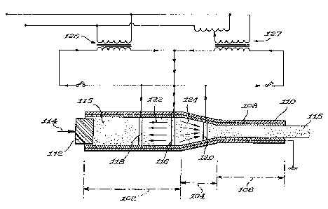
In yet another embodiment of the invention, shown
in Figure 10, there is again provided a feed section 102, a
conical section 104 and an exit section 106. For ease of
illustration, there is illustrated a single structure having
an inner non-conductive layer 108 and an outer reinforcing
layer 110. It will be understood that distinct and separate
components would normally be utilized.
A piston 112 is operated in the direction of arrow
114 to push doughmass 115 towards the exit section 106.
Mounted interiorly are three ring electrodes 116,
118 and 120 operatively connected to an electric circuit
powered by two transformers 126 and 127. In this
embodiment, using 60 Hertz ohmic heating, current passes
from ring electrode 116 which is located in the feed section
proximate the wider end of the conical section to ring
electrode 118, as indicated by arrows 122, to preheat the
doughmass passing therethrough. Current will also flow
through the conductive doughmass 115 from ring electrode.116
WO 95/18543 PCT/CA95/00010
- 23 -
to ring electrode 120, as indicated by arrows 124, to heat
the doughmass, while it is going through the conical
section, to a temperature above the heat coagulation
temperature of the heat coaguable proteins contained
therein. As a result, a fibrous texture is created and heat
set and one obtains a product with a high quality texture.
Utilizing this arrangement, one could also vary
the configuration of the electrodes to achieve a center
heating effect similar to that discussed with respect to the
embodiment utilizing microwaves.
In Figure 11 there is illustrated a modified
version of an ohmic heating apparatus. In this version, for
illustration purposes, the electrodes 130 shown are those
used for preheating inside the feed section; a similar
principle could be used in the conical section 12.
Thus, there are provided a plurality of electrodes
130 which, in Figure 11a, are shown as three electrode pairs
(Al, A2) , (B1, B2) , (C1, C2) .
As previously discussed, the material in the cone
tends to move more slowly proximate the walls of the cone
then at the center. A voltage would be applied to the
electrodes arranged in pairs opposite each other on the
circumference. Each electrode pair would be connected to a
separate transformer through a solid state relay. When the
voltage is applied to the electrodes, a current flows
through the doughmass, which is conductive in view of its
water and salt components. Accordingly, this would result
i . ~
~18~~0~ ~ ~ : ~.
24 -
in heating of the doughmass. The current would preferably
be controlled with sequential time-sharing so that only one
electrode pair is on at a given time. The current flow
between the electrodes spreads across the dough. However,
the current path is longer around the circumference than
across the diameter so that more power is absorbed in the
center. The addition of current from three electrode pairs
helps produce a relatively uniform temperature gradient
between the center and edge of the doughmass.
Figure 12 illustrates current f'.~.'ow between the
longitudinal electrodes as described in Figure 11. Thus, if
one were to consider the flow of current between two
electrodes 130 and analyze its two paths with one across the
diameter of the doughmass and the other path around half of
the circumference. Squares 132 represent elements of unit
resistance in alternative paths of current flow. Although
the discussion will be limited to current flowing in the
plane of the paper, the ratios of current are similar in a
three-dimensional analysis. For present purposes, one will
assume that the current flows in a path 1.27 cm. (.5 inches)
wide and the diameter of the conduit is 11.43 cm. (4.5
inches) with the path following the half circumference being
17.78 cm. (7 inches). Comparing the two paths, one may see
that the resistance across the diameter would be a unit of 9
with the resistance around a circumferential path being a
unit of 14. If one were to analyze the power density, one
would arrive at a power ratio of .4:1 such that there is
~IMEIVDED SHEET
<IMG>
'~ wo 9snssa3 ~ 1 g ~ ~ 0 $
PCT/CA95/00010
- 25 -
path across the diameter than in the circumferential path.
If one were to utilize a number of pairs of electrodes, it
will be seen that there would be more heat generated in the
center of the doughmass. The heating intensity follows
Poisson's laws for static magnetic and electric fields and
thus can be calculated.
Figure 13 illustrates a variation of the ohmic
heating embodiment, and in this Figure, it will be seen that
there are a plurality of electrodes which may be installed
on the inner surface of the conduit. The electrodes have a
somewhat spiral configuration and utilizing this
arrangement, one is able to provide a more even distribution
of the heat concentration which otherwise would tend to
occur near the electrodes.
It will be understood that the heating intensity
on the outer diameter of the dough would be relatively high
directly under the active electrodes and decrease rapidly on
either side of it. When the power switches to the next pair
of electrodes, this heating pattern would also move. The
average heating under the electrodes would therefore become
fairly uniform; however, there would be a minimum average
heating intensity between adjacent electrodes.
The use of spiral or curved electrodes would
function to "smear" the heating pattern to produce nearly
uniform average heating intensity on the surface of the
dough diameter. Because of the smearing of this heating
pattern, the average heating intensity would actually be
wo 9snssa3 ,~ ~ ~ ~ ~ ~ ~ rc-rica~sioooio
- 26 -
one-half of the value under the electrode.
It is preferred that the upper heating intensity
level be monitored so that undesired heating effects do not
occur. Particularly, it would be undesirable to have the
generation of high temperature steam which tends to insulate
the dough from the electrode and make the heating unstable.
One means of minimizing this problem is to increase the
surface area of the electrodes. Also, one could change the
rate at which the switching of the electrodes is
accomplished. Thus, by using solid state relays, one can
apply pulses of energy before switching to another pair of
electrodes. This procedure would allow any steam bubble to
reach equilibrium with the temperature of the surrounding
dough before additional power is induced at that point.
In one arrangement using ohmic heating, one may
operate the system such that the electrodes may be
considered as forming an electrode cage about the doughmass.
Each electrode could be connected to either side of the line
through a relay controlled by a computer and appropriate
software such that only one pair of electrodes may operate
at a time, but any two electrodes may form an electrode
pair. Thus, the electrode cage can be operated in modes
which would_provide a variety of heating patterns. One
could, as above mentioned, provide maximum center heating by
exciting electrodes 180° apart. However, if adjacent
electrodes were excited, the current flow would be confined
to the outer volume of the dough cylinder. It would thus be
~~8~~08
- 27 -
possible to provide different heating patterns adjusted for
a particular dough velocity and/or dough formulation.
Furthermore, one could utilize sensors along with suitable
control software to vary the heating pattern as required.
Still further, it is possible to combine various
of the methods described herein. One cou:Ld, for example,
provide ohmic heating in a certain region where required
such as at the exit end of the conical section. A plastic
cone section would still be compatible with a single mode
cavity microwave applicator.
~s~A~N~~~ SHIFT