Note: Descriptions are shown in the official language in which they were submitted.
4, 98~2
BACKGROUND BF THE INVENTION -
1. Field of the Invention
The pr'esent invention relates to a method of compensating
forces of force components resulting from horizontal movements of
the rolls in roll stands for hot-rolling and cold-rolling of flat
products, wherein the roll stands are equipped with work rolls and
with one or more back-up rolls, with hydraulic adjusting units and
with force measuring devices on the opposite side of the roll gap
and with hydraulic devices for the horizontal displacement of the
work rolls.
2. Description of the Related Art
When rolling flat products in hot-rolling plants and cold-
rolling plants, there is the problem that all participating rolls
are axially moved in the stand in different directions during the
rolling process and produce axial forces by pressing against the
respectively provided locking means. Together with the
corresponding reaction forces, these axial forces produce free
pairs of forces at a distance from the roll center to the contact
with the neighboring roll. Each of these pairs of forces results
2
in reaction forces in the roll bearings and, thus, in the two
housing posts of the stand.
Fig. 1 of the drawing illustrates the basic problem, for
example, in'connection with the upper back-up roll 1 of a four-high
stand. The horizontally acting forces T are linearly aligned
vectors, i.e., they can be displaced along their lines of
influence. Consequently, it is of no significance on what side of
the stand the roll is locked. Such pairs of forces are basically
always produced by the axial force in the area of contact with the
neighboring roll. The individual forces are superimposed and
manifest themselves in different axial forces at all participating
rolls and result in reaction forces in the roll housings which are
difficult to determine.
The reaction forces in the roll housings show extremely
disadvantageous effects especially in reversing stands. When the
direction of rotation is reversed, the srew-type direction of
rotation of all participating rolls also changes. The rolls travel
toward the respectively opposite sides which results in a reversal
of the axial forces. The reaction forces in the roll housings
change accordingly, so that the force measuring devices arranged in
the housings indicate changes which are in no relation to the
actual rolling process. This results in erroneous reactions of_all
3
control circuits which depend from the forceB measured in the roll
housing, such as, the planeness control, the automatic calibration
for the parallel adjustment of the roll gap, the roll alignment
control for compensating the effects of an eccentric position of
the rolled product and other control circuits depending on the type
of roll stand and rolled product.
It is already known in the art to determine by computation or
by means of measuring devices the vertical forces generated in the
stand, such as, the forces from the own weights, from the roll
balancing means and the roll bending means, and to take these
vertical forces into consideration when measuring the forces in the
two roll housings. However, such compensations have not been
carried out for reaction forces from the above-described axial
forces of the rolls.
4
SUMiARY OF THE INVENTION -
Therefore, it is the primary object of the present invention
to determine with sufficient certainty the reaction forces in the
roll housirigs without having to establish additional measuring
points in the roll stand.
In accordance with the present invention., in a method of
compensating the forces or force components resulting from the
horizontal movements of the rolls in roll stands of the above-
described type, the pressures in the two adjusting cylinders are
utilized for determining the rolling forces on one side of the roll
gap and the forces indicated by the force measuring devices are
utilized for determining the rolling forces on the opposite side of
the roll gap, and all axial forces in the stand are computed during
the rolling operation by including the axial forces of the work
rolls which can be determined through the pressures in the
displacement cylinders of the work rolls.
The method according to the present invention makes it
possible to continuously determine all vagrant forces occurring in
a roll stand from horizontal movements of the rolls and to
compensate the resulting force components in the measured rolling
forces.
CA 02182832 2006-06-08
In another aspect, the present invention provides a
method of compensating forces or force components resulting
from horizontal movements of rolls in a roll stand for hot-
rolling and cold-rolling of flat products, the roll stand
including work rolls defining a roll gap having first and
second sides, and at least one back-up roll, hydraulic
adjustment means for the rolls mounted on the first side of
the roll gap and force measuring devices mounted on the
second side of the roll gap, and hydraulic displacement
means for horizontally displacing the work rolls, the
method comprising measuring pressure supplied by the
hydraulic adjustment means for determining rolling forces
on the first side of the roll gap and measuring forces
displayed by the force measuring devices for determining
rolling forces on the second side of the roll gap, and
computing all axial forces during rolling operation by
including axial forces of the work rolls measured through
pressures applied by the displacement means on the work
rolls.
.
For a better understanding of the invention, its
operating advantages, specific objects attained by its use,
reference should be had to the drawing and descriptive
manner in which there are illustrated and described
preferred embodiments of the invention.
6
BRIEF DESCRIPTION OF THE DRAWING
In the drawing:
Fig. 1'is a schematic illustration showing the forces acting
on the upper back-up roll of a four-high stand;
Fig. 2 is a schematic illustration showing.the forces acting
in a roll stand;
Fig. 3 is a compilation of the equations representing a force
equilibrium in the stand;
Fig. 4 is a compilation of equations for the reaction forces
from the axial forces and for the reaction forces from the
eccentricity of the rolling force; and
Fig. 5 is an example of the computation of the axial forces of
the rolls and the reaction forces.
7
DESCRIPTION OF THE PREFERRED EMBODIMENT
Modern roll stands for cold-rolled and hot-rolled flat
products are equipped today almost exclusively with hydraulic
adjustment 'means 2 as the adjusting members for the thickness
control. The adjusting cylinders of the hydraulic adjustment means
are located above the upper back-up roll chocks 3 or below the
lower back-up chocks 4.
In a preferred embodiment, force measuring devices 5 are
additionally provided in the two roll housings on the opposite side
of the stand seen from the roll gap, wherein the force measuring
devices 5 serve the purpose of continuously measuring the forces
occurring during the rolling process in the two roll housings.
The two hydraulic cylinders of the hydraulic adjusting means
provide via the hydraulic pressure in a preferred manner additional
measurement values for the forces in the two roll housings, so that
measuring values for the forces in the two roll housings above the
upper back-up roll chocks and below the lower back-up roll chocks
are available without additional requirements.
Another feature of modern roll stands for hot-rolling and
cold-rolling of flat products are displaceable work rolls 6,. for
8
32
example, for influencing the roll gap profile or for-rendering the
roll wear uniform. In a preferred embodiment, the displacement of
the work rolls 6 is effected by means of hydraulic cylinders 7.
Independently of whether the two work rolls are displaced during a
phase of operation or are in a certain position, pressures are
generated in the hydraulic cylinders 7 in dependence on the axial
forces emanating from the work rolls 6. Consequently, the axial
forces of the work rolls can be determined in a preferred manner
without additional requirements for measuring the pressure in the
displacement cylinders. As a result, altogether six measurement
values are available for vertical and horizontal forces in the roll
stand.
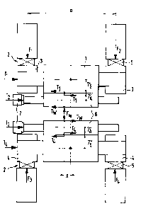
Fig. 2 shows an analysis of the forces in a roll stand. Shown
in Fig. 2 are only the forces F from the rolling process and the
axial forces T of the rolls. The balancing forces, the bending
forces and the forces resulting from weight are not shown because
the compensation of these forces is known in the art.
The statement of the equilibrium conditions for horizontal
forces T, vertical forces F and moments M at the upper and lower
sets of rolls results in altogether six equations. These six
equations GL shown below represent the force equilibrium as
follows:
9
Top of Stand: -
Vertical Forces F: Fõ - F1 - F2 = 0 GL (1)
Horizontal Forces T: T,, - Tl - T2 = 0 GL (2)
Moments M: FG, = X - Fl = a + FZ = a
2 2
- T2 (rA + rs ) + TF, (2 rA + rs ) = 0 GL (3)
Bottom of Stand:
Vertical Forces F: F,, - F3 - F4 = 0 GL (4)
Horizontal Forces T: Tw, + T3 + T4 = 0 GL (5)
Moments M: F,,, = X - F3 = a + F4 = a
2 2
- T3 (rA + rs) - Tõ (2rA + rs) = 0 GL (6)
From these six equations, it is possible via mathematical
conversions to determine the equations for the forces T1 and T.
emanating from the back-up rolls and the tangential force T,,
occurring in the roll gap. Thus, all the horizontally acting
forces occurring in the stand are known.
Fig. 3 is a compilation of the set of equations.
Of particular interest for the position of the resulting
rolling force in the roll gap is the derivation of a deviation X
from the center, as seen in Fig. 2. This value can also be
continuously determined from the six measurement values during the
rolling operation. The equation for the deviation X from center is
shown-in Fig. 3. The value X can be utilized for the automatic
calibration, i.e., for automatically placing the two work rolls in
parallel positions; this is done after a roll change by
pretensioning the stand without rolled product with rotating rolls
and computihg the eccentricity X from the six measurement values.
By carrying out a pivoting movement by means of the hydraulic
adjusting means, the value X is controlled so as to become zero, so
that the upper and lower rolls are exactly in a parallel position.
The deviation X from center can also be used for monitoring
the rolling process, particularly in reversing stands in which the
strip or sheet can travel from the center of the stand. The
deviation X from center can be utilized for reporting such events
and for carrying out an appropriate correction.
Of course, the automatic calibration and monitoring of the
rolling process can also be effected in such a way that, instead of
the introduction of the deviation from center, a correction or
compensation of the measured forces F1 through F, is effected with
the aid of the computable reaction forces from the axial forces.
The equations for the sum of the reaction forces from all
participating rolls required for this purpose are indicated with R1
through R, in Fig. 4. After such a compensation, the measurement
values F1 through F, can be utilized in the known manner by forming
il
the dif f erence F1 -= FZ or F3 - F4 for the calibration of- the rolls
and for monitoring the rolling process.
The equations for determining the axial forces of the rolls
and the deviation from center have the particular advantage that
the measurement values for the axial forces in the upper or lower
areas of the stand enter the evaluation always as differential
values. This produces the result that the friction forces
contained in the measurement values, particularly in the
measurement values from the adjusting cylinders, do not enter into
the evaluation as long as the friction forces are equal on both
sides of the stand. This is true for a determination of the
measurement values during opening movements on both sides or
closing movements on both sides of the hydraulic adjustment means.
If a pivoting movement is carried out, the friction forces of both
stand sides would be added. Consequently, the operation is to be
carried out in such a way that the determination of the measurement
values is suppressed during a pivoting movement.
It has also been found advantageous to utilize the measured
and computed axial forces T1 through T, and T, for monitoring the
state of maintenance and the exactly ground contour of the rolls.
Substantial wear of the rolls and errors in the way the rolls are
ground increase the relative inclination of the rolls and lead to
12
zncreased axial forces. Consequently, - a display of these forces is
an excellent way to continuously monitor the rolling mill.
Fig. 4 of the drawing shows the set of equations for the
reaction forces from the axial forces and for the reaction forces
from the deviation from center of the roll force.
Fig. 5 shows a computation example with assumed roll stand
data and rolling data and the axial roll forces and reaction forces
computed by means of the above-described equations.
While specific embodiments of the invention have been shown
and described in detail to illustrate the inventive principles, it
will be understood that the invention may be embodied otherwise
without departing from such principles.
13