Note: Descriptions are shown in the official language in which they were submitted.
-1-
DESCRIPTION
SLIDING COMPONENT AND METHOD OF MANUFACTURING THE SAME
Technical Field
The present invention relates to a sliding
member such as a valve train part, a cam follower, or
a rocker arm of an automobile engine and, more
particularly, to a sliding component which has a
structure of a base metal and, joined thereto, a
ceramic sliding member and which exhibits an effect
when used in a tappet, and to a method of
manufacturing the same.
Background Art
Sliding components have been selected from the
viewpoint of good abrasion resistance on the slide
face and low sliding resistance. A single material
having excellent properties has been employed or a
composite has been prepared therefrom for practical
utilization as a sliding component.
Attention has been drawn to ceramics having
excellent sliding properties in recent years.
Especially, examples of actual use are found in which
a ceramic is joined to a metal material in a manner
such that the ceramic is positioned in sliding parts
where sliding conditions are severe.
For example, there is an application where a
silicon nitride ceramic having good sliding properties
is joined to a cam sliding portion of. an engine tappet
as practiced for a high-powered engine or in
2182896
-2_
compliance with exhaust gas regulations. '
The above sliding component is occasionally
required to exhibit sliding properties at sliding
zones other than the ceramic zone or on the whole body
of the component, so that hardening treatment is
performed for improving the sliding properties of the
metal material.
Thus, the metal part is hardened by the use of
the heating and cooling effected when the ceramic is
joined to the metal by heating in the previous
Japanese Patent Laid-Open Nos. 2-55809, 2-199073, and
4-2672.
However, the above hardening relying on the heat
joining has encountered the problems that the heating
temperature applied to the sliding part of the body is
different from that employed. in the conventional heat
hardening treatment of steel, thereby occasionally
disenabling attainment of a hardness required for the
sliding performance, and that the cooling method is
special, the variety of metallic material suitable
therefor is limited and the cost is increased.
With respect to the above mentioned Conventional
problem, the present invention is directed to provide
a sliding component of higher practicability and a
method of manufacturing the same.
Disclosure of the Invention
In order to achieve the above mentioned object,
the present invention provides:
a sliding component comprising a main body made
of steel and a member adapted to form at least one
sliding face of the sliding faces and heat-joined to
the main body, the steel-made main body having been
:... .._. ...._... ._..........._. _ _.,. ... . .. .:.._..._._.. ..
;...mH..".y.,:.,m,r,.,.;.,~....~_:.-..._,......_._... .. ...~........_..._--_.
. ._.__._.._-_......
-3- 2182896
' heat-hardened before the heat-joining; and
a method of manufacturing the sliding component
characterized in that a temperature of the steel-made
main body during joining is lower than the heat-
s hardening temperature for that steel.
Constituent members of the sliding component of
the present invention are the steel-made main body
thereof which has been heat-hardened before the heat-
joining, and one or more slide faces. At least one of
the slide faces is joined to the main body by means of
heat-joining.
The main body of the sliding component before
joining has a surface hardened by means of the heat-
hardening. In addition, the temperature of the steel
portion during the joining is lower than the heat-
hardening temperature for that steel, so that the
hardness of the steel joined is almost the same
hardness as the one during the heat-hardening.
Accordingly, the sliding properties of the sliding
component of the present invention is significantly
improved as compared with conventional materials which
have been hardened during the above mentioned heat-
joining.
A hardness of the steel main body after the
joining is 45 or higher in Rockwell hardness (HRC).
With HRC of lower than 45, abrasion becomes large and
no durability is given, so that sufficient sliding
properties cannot be obtained. The hardness of the
steel body before the joining is preferably 50 or
higher in HRC scale because a slight reduction in
hardness is caused as the heat-joining.
The material of the main body of the sliding
component is steel, and the type thereof is not
. specifically limited as long as it exhibits 50 or
higher in HRC by the heat-hardening. However, carbon
2182846
-4-
steels or alloy steels including additive alloying
elements such as Ni, Cr, or Mo, which are widely used
as machine structural steels are preferable from the
viewpoints of strength, and costs for the material and
working.
A junction area between the member adapted to
form the slide face and the steel main body is
preferably 50$ or larger of an interface area
therebetween. An area smaller than this increases a
load applied to the junction portion as compared with
the breaking load at that junction portion, increasing
the possibility of the member at the slide face to be
stripped off.
The member heat-joined to the main body of the
sliding component to form the slide face is preferably
made of a silicon nitride ceramic, and a strength and
a Charpy impact value thereof at a room temperature
are 130 kg/mm2 or higher and 15 kJ/m2 or larger,
respectively.
In this event, the ceramic having the strength
of 130 kg/mm2 or higher makes it possible to withstand
a thermal tensile stress caused inside the ceramic due
to the difference in coefficient of thermal expansion
between the steel and the ceramic during the heat-
joining and to thereby avoid any cracks without any
difficulty.
In addition; considering actual state of usage,
a shock loading may act from, for example, a metal cam
in a valve train system for an engine as illustrated
in Fig. 2. In order to avoid damages of the ceramic
thereupon, it is preferable that the Charpy impact
value is 15 kJ/m2 or larger.
Furthermore, it is preferable that the
temperature of the steel during the joining is as
~18~8~6
-5-
lower as possible than the heat-hardening temperature
for that steel in order to inhibit temper softening of
the steel due to the heat applied during the joining.
For example, for a hypo-eutectoid steel, an
appropriate heating temperature during the heat-
hardening is around 800°C, which is from 30° to 50°C
higher than an AC3 or AC1 transformation temperature
at which the steel has only an austenite phase during
the heating. Accordingly, the temperature of the
steel portion during the joining is preferably as
lower as possible than 800°C. Any joining methods may
be used if the joining temperature satisfies the above
mentioned condition, and a known method may be used
such as brazing and diffusion joining.
When the member to be heat-joined is ceramic,
joining by means of brazing is conducted. For a
brazing filler material, it is preferable~to use a
brazing filler material of which joining temperature
is lower than the heat-hardening temperature. For
example, when an A1 alloy brazing filler material is
used, the joining temperature is 580°C, allowing the
joining at the significantly lower temperature than
the heat-hardening temperature.
In addition, when a brazing filler material such
as Ag-Ti or Ag-Cu-Ti whose joining temperature is
higher than the heat-hardening temperature for the
steel, it is preferable that the temperature of the
steel portion is decreased to the lower temperature
than that of the brazing filler material portion, and
the joining is conducted with the temperature of the
steel portion kept lower than the heat-hardening
temperature.
Specifically, it is preferable to use a method
of heating only the brazing filler material portion by
2~8~896
-6-
means of, for example, high frequency heating, mi-
crowave heating, or laser heating, or a method of
heating at a gradient temperature with the ceramic
portion being at a high temperature and the steel
portion being at a low temperature by means of, for
example, electric heating or plasma heating. In
addition, a brazing atmosphere is preferably a non-
oxidation atmosphere (vacuum, Ar, N2, H2, etc.).
Brief Description of the Drawings
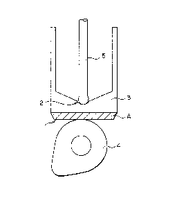
Fig. 1 is a view for use in describing a tappet
to which the present invention is applied.
Fig. 2 is a view for use in describing a using
state for a tappet.
Fig. 3 is a view for use in describing a method
of joining a sliding member to a steel-made main body
Denotation of Symbols
1 Slide face
2 Slide face
3 Tappet main body
4 Cam
5 Push rod part
A Sliding member
6 Carbon-made mold for heating
7 Silicon nitride
8 Brazing filler material
9 Steel main body
10 Thermo-couple
11 Thermo-couple
Best Mode for Carrying Out the Invention
2~ 8896
The present invention is described specifically
in conjunction with examples.
Example 1
Fig. 1 shows a tappet manufactured as an example
of a sliding component according to the present
invention. This tappet has, as apparent from the
actual state of usage illustrated in Fig. 2,
significantly severe slide conditions for a slide face
1 and a push rod contact face 2. A silicon nitride
sliding member A is joined thereto by means of brazing
according to the present invention to form the slide
face 1, and the steel of the push rod contact surface
2 keeps almost the same hardness as the one obtained
during the heat hardening. It is noted that, in Fig.
2, 4 indicates a cam, 5 indicates a push rod part.
The silicon nitride sliding member A was~manufactured
in the manner described below.
To a commercially available silicon nitride
powder 5~ by weight of Y203 and 2~ by weight of A1203
were added as sintering aids, which was mixed in
ethanol by a ball mill for 48 hours. After dried, the
resultant mixed powder was pressed and subjected to
CIP, and then subjected to HIP treatment for 1 hour at
1650°C in a nitrogen gas atmosphere of 2 atm.
A material of 30 mm in diameter and 1 mm in
thickness was cut out of the resultant sintered body,
and a flat surface to be served as a slide face was
worked to have a flatness of 10 um and a surface
roughnesys of 0.3 um or lower (ten point average rough-
ness). Mechanical properties of the resultant
sintered body are shown in Table 1 below.
.2182896
-8-
Tabl~ 1
Mechanical Properties
Flexural Strength 135 (kg/m2)
Charpv Impact Value 15 2(kJ/mm2)
The tappet main body 3 used was an alloy steel
for machines, chromium steel SCr440 (JIS G4104).
After working, it was heated to 850°C and subjected to
the heat-hardening in oil. Thereafter, the sliding
member A and the tappet main body 3 were brazed
through an aluminum alloy brazing filler material
(JIS-BA4145) of 100 um in thickness, by using a common
resistance heating furnace with a method of keeping it
in vacuum at 570°C for 30 minutes.
As a comparative example, SCr440 without being
subjected to the heat-hardening was used as the body
3, and joined to the sliding member A in the same
manner as in the above.
The joined tappets so manufactured were measured
in hardness of the slide face 2, and were incorporated
into a commercially available diesel engine of OHV
type, which were subjected to a durability,test for
2000 hours at an engine rotation speed of 1000 rpm by
using a deteriorated oil. An abrasion loss of the
slide face 2 was measured.
Table 2 shows the results on the hardness of the
slide face 2 before and after the joining and the
abrasion loss. Provided that the determination on the
abrasion loss is: "None" for a case where the abrasion
loss is less than 10 um, and "Observed" for 10 um or
more.
As indicated in Table 2, No. 1 which is an Example
with the heat-hardening shows
-- ~_ 21 828~~
_g_
only a slight deterioration in hardness before and
after the joining, and are superior in hardness and
abrasion resistance to No. 4 which is a Comparative
Example without the heat-hardening.
As in No. 1, heat-hardened steel materials and
brazing filler materials indicated in Nos. 2 and 3
were selected, brazing was conducted in vacuum at the
respective joining temperatures, and assessment was
conducted. In addition, as comparative examples,
steel materials Nos. 5 and 6 without heat-hardening
were used for the assessment thereof. For each case,
Examples are superior in hardness and abrasion
resistance.
~ 218286
-m-
o
~ v
v v v > > >
N
z z z n v
0 0 0
v
v ~
b -~
b v ~n M ~n ~r o0 0
O ~
-~ -IJ l~ l~ d~ N N
U -rl
W
O
v7 ~
U r'7
W
~
O
-
N
r-I
~
~i
N
v
v
v v
U O
3
~ s~
ro -~
-x
'U O O N O u7 O u7
Gv G
U
- ~ lD In N M
ro O
fY. N
x
wh
i
rnro
U U U U U U
-ri o 0 0 0 0 0
v
-~ I~ N O I~ N O
E
Sa
~ ~ ~ ~ ~n tD o0
N
h
H
I
'
~~ O rnro trro ~, rnro ~rd
v r-1 C"" ("., Q '(.," ~" ,~
V7 -rl ,~ ,~
.-1 r-I -r-I -r1 .-I -rl -.~
ro H N f-I N N
~ ro N N N v rl N v N v
~7
ro.u ro~ ro ro.~ b+~
~ e
~ ~~ .Q ~ ~-~ .~ .a ~
~
rnr ~ ~ _
d
N f-m- ~ f-i ~ i-a i-t
t~ ~ N N I
r-
v v v v -~ v v v v
i i r- i i
N '~ .~ r-I > r1 ~., > r-I > ~-I
v ~Q,'~,71 f11 'd' G>
ro~ ~x
~ P p0 r-1 -.i -ri v
'-' 0 P4 .~ -ri
~ G~1
a1 v U7 W C1~ V~ W r'1
~ N W W
~
a!
v . ro
H x
0 0 0
v v v v
0 0 0
W ~n o 00
~r
co 0o co
z z z
v '
~
~
N
x~~ ro
a.
~D o o ~ U
ro O O r- d~ N ~D
~ d~ N l0 d~
-.i
N ~r d~ ~ N
N
N
N U
N
U U z ro
cW U V z v7 tn cn U
d
v1
b
b
tn ~ ~ v a v ob ob ob
v
~ oro ors ow v-.~ v-~ v-~,
~,
N U U .rl U -rl -.-I -r1 -.-i
-r1 -~-1 i-1 N N
N
N -rl -r~ -rl .-1 r-1 .-I
W ~..~N f-I -1.1 .t~ .t~
b
..c~
- t~ .-1 --I r.-1 -.-I ..-1 -.-i
O -tW J.~ -tJ -.~ -ri -.~
-,-~
~
~ - - ~ t~ v~ ~ ~
~ G
~ cn v~ ~ N
c ~ ~ ~ j
l~
~
~
'a' u O
O - N
r (h -~C ~ ~ ~
z .r
Tr r
2182896
-11-
Example 2
Silicon nitride similar to the one in Example 1
was used for the sliding member A. A machine
structural alloy, chromium steel SCr420 (JIS G4104),
was used for the tappet body 3. After working, it was
heated to 800°C and subjected to the heat-hardening in
oil. Thereafter, the sliding member A and the tappet
body 3 were set through an aluminum alloy brazing
filler material (JIS-BA4343) of 100 um in thickness,
such that the junction face is located within a
carbon-made mold 6 for heating and the slide face 2
portion is exposed outside the heating carbon-made as
shown in Fig. 3. This carbon-made mold 6 was placed
in a furnace capable of rapid heating by means of a
mechanical pressurization and a pulse current. A
pulse current of 5000 angstrom was applied at an ON-
OFF ratio of 12:2 in a state of 103 Torr of vacuum
degree. The temperature of the junction face at a
t-hermo-couple 10 was increased to 620°C for 3 minutes
bY means of discharge plasma, which was kept for 5
minutes, and then cooled to a room temperature for 5
minutes to conduct brazing. The temperature of the
slide face portion at a thermo-couple 11 for No. 7 was
increased to 550°C at highest.
For No. 10, the same material similar as the one
in No. 7 was placed in a common resistance heating
furnace, and heated to 620°C to conduct the brazing.
In this case, the junction portion and the slide face
2 were both heated to 620°C.
The hardness of the slide face 2 of the joined
tappet manufactured in the manner mentioned above was
assessed before and after joining. As a result, in
the case of No. 7, Example, HRC was decreased only
from 60 to 55 before and after the joining, while in
CA 02182896 1999-12-O1
-12-
the case of No. 11 " Comparative Example, it was
decreased from 60 to 48. In addition, No. 7 exhibited'
more favorable sliding properties..
As in No. 7, heat-hardened steel materials and
brazing filler materials shown in No. 8, No. 9, and
No. 10 were selected, and heated only at the junction
face by means of electric heating, high frequency or
laser to conduct the brazing. The temperature of the
slide face at that time was lower by approximately
100°C than the temperature of the junction face. In
addition, as Comparative Examples, brazing by means of
common resistance heating was conducted for No. 12 and
No. 13. As shown in Table 3, for each case, Examples
are higher in hardness and exhibit better sliding
Properties for a sliding component.
2~ a2~g6
13-
v
b
v
zs N
~
o v
-~
tn -v.~
U ~
W 00 M O 00 ('~ O
'~
W ~ m W ~n
U O
O ~7 m
tn
_
Ul
ri
v N
N
.~
v N
-~
23 O
v G
3
N W o o m o 0 0 0
U .~
.~G
rt1 N ~O ~o t0 n ~o ~D I
rd O
U
xw wh
o
N U U U U U U U
'L5 o 0 0 0 0 0 0
v
-rl o o O O O o O
U
v r-I u7 d' O O N
(t1
~I V7 tn tn 00 CO l~ 00 01
W
fd G
N 0 U U U U U U U
G
N -'-I o 0 0 0 0 0 0
O
0 0 0 0 0 0
0
U N N Ov f~ N p1 M
-L~
N ~ ~o ~o CO oW O oo O~
N
E-~ ~
O
~7
W
bi
CT -rl
~
' b G G
v v r-I
x
U CT' ~d v U U
U ~ x U a
'r ~I b~ .~ ~ cd c
l ~T d b~
-~ rt1 N W ~ cd -iJ
CT ~
-1.J 'rl ~-t J-~ UI fn
("., rl r1
v ~ .C: v Vl -rt -r1
.iJ rl -iJ 1~
x (d ~'~ ~ -i ~ ~
~
~ ~ ' a ~
w x.~ a v~ x.~ x,~
~
b ~
~ ~ rn~
~ ~ '~' a ,~
. , ~, - , _
, N
'-i .-1
v N N
(d (f5 r-I (t~ (d rl (d
-I-! -J-~ -~J -~
b
f~ ~ r. ~ .Q ~ ~ N ~ ~ E
M ~ _
~ .4 N .-I ~ 4 N ~ ~
M N N r. ~r N r
~ -~ v i v v -~ . v v
~r i M v i i
b ~~ ~~ ro~~
~
. ~~z ~~ ~~~ ~~z
~
o ~~ ~ ~w zw~ ~ ~~ a
v~ ~ ~
x
,.. w ~, z~i
.,
v
N
~', 1~
-~i td
O N U U U
b ~
-a 0 0 0 0 0 0 0
t~
rt1 N o o m o0 o m op
~
v ~d o~ co 00 o0 o0 00 00
v
xxH
rd o 0 0 ~0 0 0
N N d~ ,-
~-I N d~ '
d dy O
N N
N -t~ is f~ ~ ~ N
U
00 01 O r- N lh
~..~--~w.~_-_~._-_.-~ _ . __._.-~~.-.._..: ~..~. -, _ ~~ . : -~ ~-: _ . __ _
_._.:. _:. ~ _ ..
2~ 8~~g6
-1 4-
' (note) * indicates Comparative Examples
Example 3
Ten silicon nitride sliding member A having the
properties shown in Table 4 below were manufactured
for each of Examples and Comparative Examples, and
each was joined to SCr 440 by brazing in the same
manner as in Example 1.
When the silicon nitride of Example was used,
good joined bodies were obtained for all of ten
samples. When the silicon nitride of Comparative
Example was used, cracking occurred in five silicon
nitride portions of ten joined bodies since they
couldn't withstand the thermal tensile stress caused
inside the ceramic due to the difference in
coefficient of thermal expansion between the steel and
the ceramic during the heat joining. The joined
tappets manufactured (ten tappets in Example and five
in Comparative Example) in which no cracking occurred
in the silicon nitride were examined for their
interface at the junction portion by means of
transmission X ray. As a result, the joined area of
the joined bodies of Example was from 75 to 100 of
the junction interface area. On the other hand, it
was from 30 to 48~ in Comparative Example.
Next these
joined tappets (ten tappets in
Example and five in Comparative Example) were each
incorporated into a commercially available diesel
engine of OHM type, which were subjected to a
durability test for 2000 hours at an engine rotation
speed of 1000 rpm by using a deteriorated oil. As a
result, ten joined bodies of Example were all good
while among the five samples of Comparative Example,
two samples were broken in their silicon nitride
portions due to the shock loading from the metal cam,
2 ~ 8896
-15-
and the silicon nitride portions were peeled from the
steel main bodies for the remaining three samples.
Table 4
Example Comparative Example
Flexural Strength 135(kg/mm2) 105(kg/mm2)
Charpv Impact Value 15.2(KJ/m2) 12 8(KJ/m2)
Table 5
Joined Area Number of Joined Bodies
Broken
Upon Upon Durability
Joining Test
Example 75-100 0/10 0/10
Comparative 5/5 (peeling
Example 30-48~ 5/10 occurred in
three samples)
Industrial Applicability
As mentioned above, this invention has an effect
of significantly improving the sliding properties by
means of a simple manner in which a steel which has
been heat-hardened before joining is used as the
steel-made main body in the joined sliding component.
Therefore, the present invention provides sliding
components such as a valve train part, a cam follower,
a rocker arm of an automobile engine and the
production process thereof.