Language selection

Search

Patent 2183032 Summary

Third-party information liability

Some of the information on this Web page has been provided by external sources. The Government of Canada is not responsible for the accuracy, reliability or currency of the information supplied by external sources. Users wishing to rely upon this information should consult directly with the source of the information. Content provided by external sources is not subject to official languages, privacy and accessibility requirements.

Claims and Abstract availability

Any discrepancies in the text and image of the Claims and Abstract are due to differing posting times. Text of the Claims and Abstract are posted:

  • At the time the application is open to public inspection;
  • At the time of issue of the patent (grant).
(12) Patent: (11) CA 2183032
(54) English Title: METHOD FOR MAKING SLOTS IN METAL PIPE
(54) French Title: PROCEDE DE REALISATION DE FENTES DANS DES TUYAUX METALLIQUES
Status: Expired
Bibliographic Data
(51) International Patent Classification (IPC):
  • B26F 1/38 (2006.01)
  • B21C 37/06 (2006.01)
  • B21C 37/30 (2006.01)
  • E21B 43/08 (2006.01)
(72) Inventors :
  • HRUSCHAK, LAWRENCE ALEXANDER (Canada)
(73) Owners :
  • RGL RESERVOIR MANAGEMENT INC. (Canada)
(71) Applicants :
  • HRUSCHAK, LAWRENCE ALEXANDER (Canada)
(74) Agent: TOMKINS, DONALD V.
(74) Associate agent:
(45) Issued: 2001-07-17
(22) Filed Date: 1996-08-09
(41) Open to Public Inspection: 1998-02-10
Examination requested: 1998-05-08
Availability of licence: N/A
(25) Language of filing: English

Patent Cooperation Treaty (PCT): No

(30) Application Priority Data: None

Abstracts

English Abstract


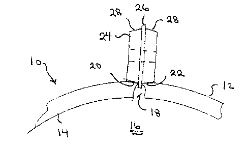
A method for making slots in metal pipe and, in
particular, slots less than 15 thousandths of an inch in width.
Firstly, providing a metal pipe having an exterior surface and
an interior surface which defines an axially extending interior
bore. Secondly, cutting an axially extending elongate slot
having a width that is larger than desired in the pipe with a
cutting tool. The slot extends through the pipe providing
fluid communication from the exterior surface to the interior
surface. The slot has longitudinal peripheral edges. Thirdly,
applying pressure to the exterior surface of the pipe along at
least one of the longitudinal peripheral edges of the slot
until the metal pipe is deformed sufficiently to close the slot
to a desired width.


French Abstract

Méthode pour réaliser des fentes dans un tuyau métallique, en particulier des fentes d'une largeur de moins de 15 millièmes de pouce. Premièrement, utiliser un tuyau métallique ayant une surface extérieure et une surface intérieure définissant un trou intérieur dans la direction axiale. Deuxièmement, réaliser dans le tuyau une fente allongée en direction axiale plus large que nécessaire, à l'aide d'un outil coupant. La fente traverse le tuyau, permettant ainsi à du liquide de passer à l'intérieur du tuyau. La fente comporte des bords périphériques longitudinaux. Troisièmement, appliquer une pression sur la surface extérieure du tuyau le long d'au moins un bord périphérique longitudinal de la fente jusqu'à ce que le tuyau métallique soit suffisamment déformé pour fermer la fente à la largeur souhaitée.

Claims

Note: Claims are shown in the official language in which they were submitted.


THE EMBODIMENTS OF THE INVENTION IN WHICH AN EXCLUSIVE PROPERTY
OR PRIVILEGE IS CLAIMED ARE DEFINED AS FOLLOWS:

1. A method for making slots in metal pipe, comprising the
steps of:
firstly, providing a metal pipe having an exterior surface
and an interior surface which defines an axially extending
interior bore;
secondly, cutting an axially extending elongate slot
having a width that is larger than desired in the pipe with a
cutting tool, the slot providing fluid communication from the
exterior surface to the interior surface, the slot having
longitudinal peripheral edges; and
thirdly, applying pressure to the exterior surface of the
pipe along at least one of the longitudinal peripheral edges
of the slot until the metal pipe is deformed sufficiently to
close the slot to a desired width.

2. The method as defined in Claim 1, having pressure applied
by a roller.

3. The method as defined in Claim 2, the roller having a
centering and a deformation controlling guide flange.

4. The method as defined in Claim 1, having pressure applied
to each of the longitudinal peripheral edges of the slot.

Description

Note: Descriptions are shown in the official language in which they were submitted.


21 83~32
.


TITLE: OF Ti~E ll~v~-~

method for making 310ts in metal pipe


~IAME OF lhvc,~,,On:

Lawrence ~l~YAn~r Hruschak


FI13LD OF THE INVENTION

The present invention relates to a method for making slots
in metal pipe and, in particular, slots less than 15
~hon~An~ths of an inch in width.


Rl~l OF THE ll~vc.l~-.ll .

The oil industry uses slotted metal pipe as a screening
~hAn;~m when ~rill;ng for heavy oil. Heavy oil is commonly
found in oil bearing sand formations. Oil wells are drilled
that have horizontal ~ection~, which can be 1000 meters or more
in length. These horizontal sections have a tendency to
collapse and become filled with sand. In order to prevent this
from ocaurring, slotted metal pipe is placed in the horizontal
section~. The sand is supported by the metal pipe, while the
heavy oil seeps through the 310ts into the pipe where it can
be pumped to surface.
It is not unusual for the slots to have a width of between
25 and 15 ~h~n~An~ths of an inch. Even with slots of that
width, some sand enters the pipe. In order to further re~trict
the entry of sand into the pipe, the industry is ~' n~ing
slots of less than 15 tholl~An~ths of an inch. It has yet to
be det~rmin~d how small the slot3 can be without unduly
restricting the rate of flow into the pipe. It has been

~ 2l~32

speculated that between 5 and 7 tho~ n~th~ of an inch will be
optimum. Unfortunately, most slot cutting equipment is unable
to cut slots with a width of less than 15 thnn~n~th~ of an
inch.


SUMMARY OF THE l~V~

What ia required is a method for making slots in metal
pipe that is better suited for making slots less than 15
thnl~An~th~ of an inch in width.

According to the present invention there is provided a
method for making slots in metal pipe. Firstly, providing a
metal pipe having an exterior surface and an interior surface
which defines an axially extending interior bore. Secondly,
cutting an axially extending elcngate slot having a width that
is larger than desired in the pipe with a cutting tool. The
slot extends through the pipe providing fluid c~ tion
from the exterior surface to the interior surface. The slot
has longitudinal p~r;ph~ral edges. Thirdly, applying ple~uLe
to the ~t~r; or surface of the pipe along at least one of the
longitudinal p~r; ph~r~ 1 edges o~ the slot until the metal pipe
is deformed sufficiently to close the ~lot to a desired width.

With the method, as described above, 3hort comings in
cutting equipment are UV~L~ by applying pressure until the
material surrounding the slot yields to narrow the slot to a
desired width. There are a va~iety of ways that this can be
done. A preferred manner of applying pL~8~L~ is by means o~
a roller.

~RIEF __ r~ll OF THE DRAWINGS

These and other features of the invention will become more
apparent from the following description in which reference is
made to the ~rp~n~ed drawings, wherein:

~ ~ ~3~
.


FIGUR~ 1 is a side elevation view, in cut away section,
of a pipe which i8 in the process of being slotted in
accordance with the t~h;ngs of the present method.
FIGURE 2 is a side elevation view, in cut away section,
of a slot in the pipe illustrated in FIGURE 1, being treated
by a ~Le~uLe roller.
FIGURE 3 is a 3ide elevation view, in cut away section,
of a pipe that has been slotted in accordance with the
te~hing~ of the present method.

ll~TDTT.~n ~S~lr__ OF T~E ~r~r~ E~BODIMENT

The preferred method for making slots less than 15
tholly~n~ths of an inch in width in metal pipe will now be
described with reference to FIGURES 1 through 3.

Referring to FIGURE 1, firstly, provide a metal pipe 10
having an exterior surface 12 and an interior surface 14 which
defines an axially extending interior bo}e 16. Secondly, cut
an axially e_tending elongate slot 18 having a width that is
larger than desired in metal pipe 10 with a cutting tool (not
shown). The cutting tool can take various forms from milling
~--hin~ to lagers. Slot 18 extends through pipe 10 providing
fluid c i~tion from exterior surface 12 to ;nt~r;or
surface 14. Slot 18 has longitudinal p~riph~ral edges 20 and
22. To this point the steps involved in the preferred method
do not m-t~r;~lly differ from the steps taken in the prior art.
In the prior art, slot 18 would be cut precisely to the desired
width. With the present method, slot 18 is deliberately cut
having a width that is larger than degired, ag a pr~l;min~ry
step in the method.

Referring to FIGURE 2, thirdly, applying pressure to
~Yt~r; ~r surface 12 of pipe 10 along one or both of
longitudinal pPr;ph~ral edges 20 and 22 of slot 18 until metal
pipe 10 ig ~f~ snffi~;~ntly to close slot 18 to a desired

2 ~ ~3~32
.


width. The key to the present method is to apply ~L~8~UL~ that
exceeds the yield strength of the ~-t~r;~l to narrow the slot.
There are a variety of means by which this may be done. For
example, by mean~ of a stamp or punch, by means of a seaming
tool. The preferred manner of applying pressure, however, is
by means of a roller 24, as illustrated. The use of roller 24
has a number of advantages. Roller 24 can be ~l;pp~d with a
guide flange 26 that centers roller 24 in slot 18 and limits
the deformation of the material when pressure i~ applied. The
pressure on roller 24 can be regulated more easily than other
methods. Roller 24 can be shaped with sloping contact surfaces
28 that help lo~ e the pressure along longitudinal
p~r;rh~ral edges 20 and 22 to achieve the desired deformation.
Roller 24 is viewed as being more readily incoL~oL~ted into
- -h~ni ~ed slot cutting equipment.

Referring to FIGURE 3, there i8 illustrated slot 18 after
it has been narrowed by roller 24. The resulting slot 18 has
desirable properties for the intended screening ~ppl; ~t;~n.
It has a narrow opening 30 of 5 thon~An~th~ of an inch at
exterior surface 12. Past opening 30 it has an enlarged
portion 32 of 15 tho~ n~ths of an inch or wider. Thi~ i~
desirable as grains of sand fine enough to temporarily wedge
into narrow opening 30 will tend to be pushed by pres~ure
through enlarged portion 32 into interior bore 16 of pipe 10,
rather than blocking off slot 18. Enlarged portion 32 also
results in a decrease in pres~ure 1088 across narrow opening
30 of slot 18.

It will be apparent to one ~killed in the art that
~;fi~ations may be made to the illustrated o~; t without
departing from the spirit and scope of the invention as
hereinafter defined in the Claims.

Representative Drawing
A single figure which represents the drawing illustrating the invention.
Administrative Status

For a clearer understanding of the status of the application/patent presented on this page, the site Disclaimer , as well as the definitions for Patent , Administrative Status , Maintenance Fee  and Payment History  should be consulted.

Administrative Status

Title Date
Forecasted Issue Date 2001-07-17
(22) Filed 1996-08-09
(41) Open to Public Inspection 1998-02-10
Examination Requested 1998-05-08
(45) Issued 2001-07-17
Expired 2016-08-09

Abandonment History

Abandonment Date Reason Reinstatement Date
2000-08-09 FAILURE TO PAY APPLICATION MAINTENANCE FEE 2000-11-24

Payment History

Fee Type Anniversary Year Due Date Amount Paid Paid Date
Application Fee $0.00 1996-08-09
Registration of a document - section 124 $0.00 1997-02-27
Registration of a document - section 124 $100.00 1997-04-11
Registration of a document - section 124 $100.00 1997-08-19
Request for Examination $200.00 1998-05-08
Maintenance Fee - Application - New Act 2 1998-08-10 $50.00 1998-08-10
Maintenance Fee - Application - New Act 3 1999-08-09 $50.00 1999-08-09
Reinstatement: Failure to Pay Application Maintenance Fees $200.00 2000-11-24
Maintenance Fee - Application - New Act 4 2000-08-09 $50.00 2000-11-24
Advance an application for a patent out of its routine order $100.00 2000-11-27
Final Fee $150.00 2001-04-19
Maintenance Fee - Patent - New Act 5 2001-08-09 $75.00 2001-08-08
Maintenance Fee - Patent - New Act 6 2002-08-09 $75.00 2002-07-30
Maintenance Fee - Patent - New Act 7 2003-08-11 $75.00 2003-07-31
Maintenance Fee - Patent - New Act 8 2004-08-09 $100.00 2004-08-09
Maintenance Fee - Patent - New Act 9 2005-08-09 $100.00 2005-08-04
Maintenance Fee - Patent - New Act 10 2006-08-09 $125.00 2006-08-09
Maintenance Fee - Patent - New Act 11 2007-08-09 $325.00 2007-09-25
Maintenance Fee - Patent - New Act 12 2008-08-11 $125.00 2008-08-11
Maintenance Fee - Patent - New Act 13 2009-08-10 $325.00 2010-07-21
Maintenance Fee - Patent - New Act 14 2010-08-09 $125.00 2010-07-21
Maintenance Fee - Patent - New Act 15 2011-08-09 $225.00 2011-08-02
Maintenance Fee - Patent - New Act 16 2012-08-09 $225.00 2012-08-07
Maintenance Fee - Patent - New Act 17 2013-08-09 $225.00 2013-07-17
Registration of a document - section 124 $100.00 2014-07-31
Maintenance Fee - Patent - New Act 18 2014-08-11 $425.00 2015-07-30
Maintenance Fee - Patent - New Act 19 2015-08-10 $225.00 2015-07-30
Registration of a document - section 124 $100.00 2015-08-17
Registration of a document - section 124 $100.00 2016-03-03
Owners on Record

Note: Records showing the ownership history in alphabetical order.

Current Owners on Record
RGL RESERVOIR MANAGEMENT INC.
Past Owners on Record
HRUSCHAK, LAWRENCE ALEXANDER
I.S.I. CANADA INC.
INTERNATIONAL SCREEN INC.
MCLEAN, TERRY JAMES
REGENT TECHNOLOGIES LTD.
VENNING, LAURIE ALFRED
Past Owners that do not appear in the "Owners on Record" listing will appear in other documentation within the application.
Documents

To view selected files, please enter reCAPTCHA code :


To view images, click a link in the Document Description column. To download the documents, select one or more checkboxes in the first column and then click the "Download Selected in PDF format (Zip Archive)" or the "Download Selected as Single PDF" button.

List of published and non-published patent-specific documents on the CPD .

If you have any difficulty accessing content, you can call the Client Service Centre at 1-866-997-1936 or send them an e-mail at CIPO Client Service Centre.


Document
Description 
Date
(yyyy-mm-dd) 
Number of pages   Size of Image (KB) 
Cover Page 1998-02-24 1 43
Cover Page 1996-11-15 1 10
Abstract 1998-02-09 1 16
Description 1998-02-09 4 126
Claims 1998-02-09 1 22
Drawings 1998-02-09 1 7
Cover Page 2001-07-09 1 34
Cover Page 2000-12-12 1 43
Representative Drawing 2000-12-12 1 3
Representative Drawing 1998-02-24 1 3
Abstract 2001-07-16 1 16
Claims 2001-07-16 1 22
Drawings 2001-07-16 1 7
Description 2001-07-16 4 126
Representative Drawing 2001-07-09 1 5
Fees 2004-08-09 1 32
Correspondence 2011-04-20 1 11
Correspondence 2011-04-20 1 15
Fees 2003-07-31 1 24
Prosecution-Amendment 1998-10-23 2 87
Prosecution-Amendment 2000-11-27 7 175
Prosecution-Amendment 2000-12-06 1 1
Fees 2000-11-24 1 38
Fees 1998-08-10 1 47
Fees 2001-08-08 1 31
Fees 2002-07-30 1 27
Correspondence 2001-04-19 1 34
Assignment 1996-08-09 14 617
Prosecution-Amendment 1998-05-08 1 44
Fees 1999-08-09 1 36
Fees 2005-08-04 1 25
Fees 2006-08-09 1 26
Correspondence 2007-09-25 1 45
Fees 2007-09-25 1 31
Correspondence 2007-10-17 3 170
Fees 2008-08-11 1 29
Fees 2011-08-02 1 201
Correspondence 2009-09-21 2 216
Correspondence 2011-03-31 3 155
Assignment 2014-07-31 2 89
Fees 2015-07-30 1 33
Correspondence 2015-08-12 2 56
Office Letter 2015-08-21 1 22
Office Letter 2015-08-21 1 25
Assignment 2016-03-03 11 307