Note: Descriptions are shown in the official language in which they were submitted.
t ~ 2183~9~
METHOD AND APPARATUS FOR MANAGEMENT OF
WASTEWATER EFFLUENT FROM VARIOUS WASTEWATER EFFLUENT
SOURCES
FIFI n OF THF INVENTION
This invention relates generally to the f eid of pollution control,
and, more particularly to the field of water pollution control and wastewater
" ~anayG-' "enl.
BACKGROUNn OF THF INVFNTIQN
Wastewater treatment methods are known and have been
used extensively, with varying degrees of success, to reduce or prevent
human and industrial wastes from polluting or otherwise fouling the
15 environment. Manydifferent processesare used in w-~t~: ' treatment,
including aerobic and anaerobic digesters, aeration, flltration, flocculation,
liquid/solid sepdldliull and others. In general however, wa;it~
treatment equipment and processes are designed to acco" " "oddl~ and treat
Wd~ .:'a ~r inputs of known and tested qualities and quantities. Typically,
20 an analysis of the v,/a:ite.va~Ar stream is performed. This analysis is used
as the basis for designing the v~ . .. ' treab~nent process, as to size, type
of equipment and types of pollutants dealt with. Thus, the wastewater
treatment process is optirnized for the particular efffluent stream to be
treated. While ensuring optimal pluces~ g of any particular v, ' .: ~:
25 source, a diffflculty arises when the v ' .:. ' includes different constituent
elements, or qualities and quantities other than the process parameters
upon which the processes' design was based.
One particular example is the treatment of oily waste.
Typically, oily waste is treated in a much diflferent fashion than, for example,30 black water or grey water. Oily waste, if introduced into a conventional
sewage treatment system tends to foul the col,l~Jol1e"tb and render the
~8314~
--
-3-
treatment system ineffective and at times i"o,ue,dble. Yet, there are
sources of black water and oily waters that need to be treated for example,
ships. Such effluent typically includes bilge water, which may have up to
three to five percent oil in water, as well as black and grey water waste
5 generated during a voyage. Therefore, what is desirable is a wavL~
treatment system which is capable of safely and efFiciently treating different
types of ~ &v'~..u~-r sb-eams, and in particular, wastewater streams
including oily wastes, without fouling components of the b~' ' ... '
treatment system.
Another aspect of conventional wastewater treatment
processes and equipment, is that they tend to be located in large scale
plants in a particular location. Small communities such as resorts or
residential areas, mining or lumber camps, may produce black water, grey
water and other b'l ' wa.-,. effluent, but not have a sufficient pvlllldnell
15 population to justify a traditional V~vdv~ .. ' treatment plant. For example,a wastewater treatment plant of sufficient capacity to treat residential
w~stA.:~ ' could be located near or in a residential area. Alternatively, a
- treatment plalt may be located adjacent to or as part of an
industrial complex, such as a mine and used to treat wastes prior to
20 releasing an effluent back into the environment. Further, mobile
populations which create and are required (under legislation) to store
wav'~.~?'~, such as ships, need access to dispose of wastewater at land
based plants which may or may not be readily available. Therefore, what
is also required are w ' .: ' treatment systems that are sufficiently
25 mobile or portable to be used in such circumstances. Preferably, such
mobile or portable w. ' . ' treatment systems should also a~vvui "" ~oddl~
variations in process inputs, such as co,,,bi,,v';v~nv of effluent from black
water, grey water, chemical or oily water sources.
21831~
; --
ARY OF THF INVFNTION
What is desired, is a lldl lvpol Ldvle w ~ '~ ~ vtv~ " ,a"agel "e"l
or treatment system and process which is capable of taking ~Vdvh .: ' from
a mixed emuent source af black water, grey water, chemical waste and/or
5 oily water and treating such w-~ ' first to remove pollutants; second,
to disinfect the water for either reuse as utility water or for release as safe
non-polluting water and Finally, to separate and disinfect any solids to
enable safe release into the environment. Preferably such a system could
receivev and treat all manner of liquid wastes except for toxic wastes. Such
10 a system, preferablywould be modularand could be contained in portable
units. For example, such a system in transportable containers could be
manoeuvred about in harbours to treat V~dutu.:-~~r from ships' sewage
holding tanks, treatment plants and bilges, or, used in remote sites, such as
mining camps or small villages to manage wv~ -r generated by
15 industryorbyalocalpopuiation. Ideally,thewav.~ .vatcrtreatmentprocess
and apparatus should be contained within conventional ll dl lv,UOI Idble units,
such as shipping containers, in order to facilitate portability and ease of
transport of the process and equipment.
According to one aspect of the present invention, there is
20 provided A method of treating v _I_r emuent from wastewater effluent
sources of one or more of black water, grey water, oily water and chemical
w&v'U~rvtv., said method ~,u,,,p,ivi,,g the steps of:
a) separating oil from a wvv'~..-'~r efifluent in a liquid/liquid
vr,ua,dliùll step to produce cundiliulled oil and oilywater;
b) adding the oily water to the remainder of the wastewater to
be treated;
C) I l ldC~vl " 19 the combined Wdvtt~ . . ' ~ stream of step (b) to
form a flowable slurry;
d) removing solids from said flowable slurry through a
dewatering step;
e) divil le~ ' Ig the water resulting from step (d); and
~ 21~3~46
-5--
f) dehydrating the solids from step (d) to produce sterile
anhydrous powder,
wherein said Wdat .:'~ ' I l ldlla~3l 11131 ll process is contained in a plurality of
modules which when combined treat waste from mobile and mixed sources.
According to another aspect of the present invention there is
provided a method of treating v~ ~ L~, ' effluent from wastc~ ' eflluent
sources of one or more of black water, grey water, oily water and chemical
wastewater, said method co",~ ,i"g the steps of:
a) installing wa~,t~ " Idl ,au~" ,~"1 equipment in at least two
easily lldllspolldl.l~ collldillela,
b) transporting said containers to said source of wastewater;
c) connecting said containers together with process piping to
form an apparatus for managing said ~a:ite. ' - effluent from said one or
more sources;
d) separating oil from said w~t~. ' effluent to be treated in
a liquid/liquid sepal~lion step to produce co, ,diliulled oil and oily water;
e) adding the oily water to the remainder of the v~ tcr to
be treated;
f) macerating the combined w ' ... ' stream of step (e) to
form a flowable slurry;
g) removing solids from said flowable slurry through at least
one cle .:. ' i"g step;
h) .li~ Ce~ ,g the water resulting from step (g); and
i) dehydrating the solids from step (g) to produce sterile
anhydrous powder.
According to a further aspect of the present invention there is
provided an apparatus for managing Wd~ said apparatus ~;o" ,~ iuu.
at least two portable containers containing water
Illdnag~ln~ equipment including:
an oil separation module for a liquid/liquid sepd,dliun of oil
from water;
~ 218314S
-6-
a regrind module for forming a fine slurry frcm any solids in the
a dissolved air flotation module for sepd,dli"g said fine slun y
solids from said wa:jt.. .AI~I,
a sludge ,md"agv" ,el ll module for dewatering said separated
solids;
a di~ ivll and oxidation module for di~i,,f~vli,,!J water
separated from solids in said dissolved air flotation module and said sludge
I l Idl Idyvl I le:l 11 module;
a utility water tank module for storing water; and
process piping connecting said modules together, said process
piping including extension piping to extend between said containers,
wherein said containers are individually lld"spoll~l)le to a
source of W-'-N~~: ' - and are co, " ,evldble by said extension piping to form
said w-~f~:-. ' "~anay~"~t:"l apparatus.
~IFF DESCF~IPTION QF THE DRAWINGS
Reference vwill now be made, by way of example only, to
preferred embodiments of the present invention by referring to the attached
drawings in which:
Figure 1 is a functional diagram of a modular ~ ' ..A'-r
effluent treating system according to the present invention;
Figure 2 is an oil sepd, ' ~ (OS) module of Figure 1;
Figure 3 is a view of a regrind module of Figure 1;
Figure 4 is a view of a dissolved air flotation (DAF) module of
Figure 1;
Figure 5 is a view of a di~i,,r~vvtivn and oxidation/filtration
(DOF) module of Figure 1;
Figure 6 is a view of a sludge l"d~age"~e"l (SM) module of
Figure 1;
Figure 7 is a utility water tank (UvVT) module of Figure 1;
~ '~1831~
-7-
Figure 8 is a detail view of the disi"r~:1Lic n and
oxidation/filtration (DOF) module according to the present invention;
Figure 9 is a plan view of the modules of the present invention
installed in two ~.UI Ildil ll~
Figure 10 is a side view of Figure 9 along line A-A;
Figure 11 is a side view along line B-B in Figure 9;
Figure 12 is a side view along lines C-C of Figure 9; and
Figure 13 is a side view along lines D-D of Figure 9;
DETAILED DESCRIPTION OF THE PRE~LI~REu EMBODIMENTS
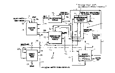
The present invention, as shown in Figure 1, is a w~
treatment system 10 which is comprised of a number of discrete modules as
described in more detail below. These modules include an oil sepa,dLiun
(OS) module 12, a regrind module 14, a dissolved airflotation (DAF) module
16, a sludge ",anagel"e"L (SM) module 18, a di~i"~ ' In and
o~iddliul1ti" dliul1 (DOF) module 20, and a utility water tank (UWT) module
22.
The first module is the oily water separation module shown as
12. The OS module 12 has an input of oil and water through line 24.
Through a liquid/liquid sepaldliol1 step, which is described in more detail
below, oily water (which is primarily water but with up to 10 percent by
weight oil) is dewatered and treated within the OS module 12 to produce an
alternate fuel source. Two outputs from OS module 12 are shown: one
through line 26 is primarily water being sent out for further treatment and the
other is oil which is removed through line 28. In some cases the oil may be
used as a fuel source in for example the sludge " ldnag~l, ,e, ll module 18 as
described in more detail below.
The next module is the regrind module 14 which receives black
water through inlet 30 and grey water through inlet 32. Line 26, having
primarily separated water from the OS module 12 as described above, is
also fed into the regrind module 14. Also shown is a make-up water line 34
2~831~
, --
-8 -
from the UWT module 22. All these lines fomm inputs into the regrind
module 14. The ,u,uces:,i"g which takes place in module 14 is described in
greater detail below. A vent 36 is also provided (to ensure the process
functions at ' llosphtric conditions) as well as a main discharge line 38 for
5 sending the efFluent to the DAF module 16, which is the next module in the
treatment system 10.
The emuent is Lldn .r~"~d from regrind module 14, by a
pump 40 (shown in Figure 3) through line 38 into the DAF module 16. The
DAF module 16 utilizes dissolved air flotation technology to separate water
1û from the eflfluent stream, thus conce,,LI " ,9 the slurry. From the DAF
module 16, collce"LI~Ltld slurry is fed through line 42 to the SM module 18.
Water is removed through line 44 and is Lldll~f~llttd to the DOF module 20.
A back flush line 46 is shown taking water from the DOF module 20 to the
DAF module 16. Also shown is a make-up water line 48 from the UWT
15 module 22.
The DOF module 20 treats effluent from the DAF 16 and the
SM modules 18, Ll~llsuoll~d through lines 44, 50 and 52 respectively.
Output from the DOF moclule 20 is clean, treated water which can be utilized
in non-potable water .,, ' ' Is. The water di~ulldlyed at 54 from the
DOF module 20 may be further treated, if desired, to make it potable, which
is shown by line 56 or may be pumped into a utility water tank 22 through
line 58.
Returning to the SM module 18, the sludge ,I,dl,agdl,,e,lL
module 32 thickens sludge and then dewaters the sludge through, for
example, a dehydrator shown as 60 in Figure 6. From the SM module 18
there are three outputs. These are solids removed by line 62, ~ndellsdLtt
removed by line 5û (which then forms an input into the DOF module 20), and
water, which is removed by line 52 (and is also input into the DOF module
20).
Also shown in Figure 1 is the UWT module 22 which simply
serves as a storage facility for water needed at various points in the process
~:L831~g
-9 -
according to the present invention. As shown, the only input line 58 is
treated clean non-potable water from the DOF module 20. The outputs
include line 34 to the regrind module 14, a back flush line 64 to the DOF
module 20, a make up water line 48 to the DAF module 16, a drain 66, and
a clean, non-potable outlet line 68. These are shown in greater detail in
Figure 7.
The individual modules can now be described in greater detail.
Turning to Figure 2, the OS module 12 is shown in greater detail. In the
event that there is oily water to treat, this module can process oily bilge
water simultaneously or i n parallel with the processing of other ~ a~
sources.
In the oil se~aration module 12 there is an oily water receiving
tank shown as 70 which i5 a gravity separation tank. In the receiving tank
70, there is a fill or input line 24, a sampling port 71 which provides the
means to determine the nature of the raw oily water mixture as well as two
output lines 72 and 74. In the oily water receiving tank 70, the oil is allowed
to float on top of the water and the effluent to be treated separates into threelayers. The bottom layer is water, the middle layer is emulsified oil and
water, and the top layer i5 oil. Skimmers (not shown) are used to skim the
oil off the top of the tank 70 through one or more exit ports shown as 76, 78
and 80, passes through a transfer pump 82, and into a heated oil tank 84.
Water is removed from the bottom of the tank through transfer pump 83 to
be sent to the regrind module 14 through line 26. Compound and pressure
gauges (shown as 86 and 88 ~ ,ueuii~cly) are preferably fitted to the
transfer pump 83 to indicate the fluid flow ul,a,d~ i tlics. It will be
ap,ul~uidl~d by those skilled in the art that such gauges 86, 88 allow proper
~"on' :i"g of pumps in the system 10 by the operators and thus are
preferred to ensure optirnal op~,dliul1dl effficiency. Thus, most if not all
transfer pumps in the system 10 are provided with like gauges 86 and 88.
The preferred It:l"~ e, ~ Ire of the heated oil tank 84, for the
present ap~, is between 60~C and 80~C, most preferably about 70~C.
~3~ 4~
-10-
The temperature of the heated oil tank 84 is, of course, dependent to a
certain extent upon the physical ul ,a, dU~ Lics of the oil being treated and
may be varied to suit specific oil types.
It will also be d,u,ul~:cidL~d by those skilled in the art that
although the material coming through the output line 74 is primarily oil, there
may still be water trapped through emul~ r ~' 1 in the oil. In addition to the
heating, a chemical emulsion breaker 90, such as AlkasurF SS-0-75, made
by Rhone-Poulenc, is injected into the effluent in a recirculation line 92
(driven by a did,ul1ld_lll pump 94) which further promotes the separation
process between the oil layer and water. As shown in Figure 2, heating is
preferably acco" I~,lk.l ,ed with a heat source 96 which transfers heat into thetank 70 through heat ~,~ul Idl ,gel 98. In the most preferred e" Ibodi" ,e"l, heat
source 96, which may be a boiler or the like, is fuelled by fuel from line 99,
which is generated by the process as described below. Fuel may also be
sent to other modules which require ener~qy, such as the sludge
l~lallayt:lllenl module 18, as shown by line 101 (which co"t~spunds to line
28 on Figure 1).
From the heated oil sepa,dliun tank 84, the feed rate of
dewatered oil is controlled by valving 97 and the dewatered oil is l, dl lar~ d
through the pump 94 by a dt~id1l Idble line 100 to a centrifuge 102, where the
oil is ~uul1ditiul1ed through centrifugal separation. The oil entering the
centrifuge preferably contains less than five percent solids by weight, and
most preferably contains less than one percent water by volume. The oil
water mixture is further dewatered by the ~;eni,iFuge, which also removes
any remaining solid matter. This con-liLiol1ed oil is .li~ul,d,_ed through line
104 and sent to a fuel oil tank 106. The resulting ,~con"" 1ed oil,
discharged from the centrifuge, is now sufflciently pure to be used as an
alternate source of fuel. This fuel is used by the present invention to fire theboiler which provides energy to heat the oil as described previously. The
separated water and solids exit the centrifuge through line 107 which tees
~ ~183146
into line 26 to join water drawn from the bottom of the oily water receiving
tank 70, all of which is sent to the regrind module 14.
Turning next to Figure 3, there is shown a schematic view of
the regrind module 14 with its various components. The inputs into the
5 regrind module 14 include black water and grey water through lines 30 and
32, oily water through line 26, (from the OS module 12), make up water from
the UWT module 22 through line 34. An automated inlet valve is shown at
108 followed by a manual valve 109, which is normally left open. Also
shown is the vent 36.
As shown in Figure 3, preferably the regrind module 14
includes a macerator 110 and progressive cavity (PC) pump 112 (preferably
a screw pump for example) on a recirculating line 114. The combination of
the macerator 110 and PC pump 112 provide the means to recirculate the
effluent stream and macerate any solids therein to form a fine slurry.
15 Recirculating the sluny ensures that particle sizes are reduced to a minimum
and prevents the formation of a sediment layer on the bottom of the regrind
tank 14. Preferably, the particle sizes of the macerated slurry range
between micron size and 1/4", and most preferably in the micron range. It
has been found that a suitable macerator 110 and PC pump 112 are the SB
20 Muncher and Monoflow E051/C1A, respectively, manufactured by Ingersoll
Dresser. Of course, it will be d,l~n~:cidl~d by those skilled in the art that
other types of " ,a el d~ g equipment and pumps can be used, provided that
a consistent slurry containing reasonably small particles is formed.
Preferably, the regrind tank 14 further includes a baffle 116
25 which is provided to dampen fluid surges thereby ",ai,ltdi"i"g a positive
suction head for a transfer pump 40 thus avoiding pump cavitation. The
baffle also prevents overly large solids from passing through the regrind tank
15, by permitting only finely ground suspended solids to pass to the transfer
pump 40. A sample station 120 has been located on the regrind module 14
30 to take samples in order to determine the 1h dl d~ lics of the eflfluent being
treated. Also provided are a high-level sensor 122 and a low level sensor
~ 21831~i;
124. These activate ar deactivate pumps, in a known manner, to
auLul"dlica'ly maintain the liquid level in the regrind tank within
p,t:d~:L~I ",i"ed set points. The set points are e~LdL~ ,ed by the location of
the sensors in the regrind tank 15. If the level falls below the low level
sensor 124, either a pump is initiated and additional water is pumped in, for
example, from the UWT module 22, or the transfer pump 4û is deactivated.
Alternately, if the high level sensor 122 is activated, inlet valves are
auLu,, ,dLiua:ly adjusted (such as automated inlet valve 108) to either redirectthe wastewater stream or decrease the influent flow rate, to prevent
overfilling of the regrind tank 14. In this manner the Wdb~ U. treatment
plant or modules thereof can fully process all wastes under steady state
steady flow conditions.
It will be noted that the transfer pump 4û (as with all transfer
pumps depicted in the w~~~m . ' treatment system 1 û) has been fitted with
compound and pressure gauges 86 and 88 to monitor the flow
ulldlduLt~ liu~ atthe pump suction and discharge, respectively.
Turning now to Figure 4, the DAF module 16 is shown in
greater detail. The slurry from the transfer pump 40 is delivered to a DAF
cell 126 via a static mixer 128 which has three separate stages, 130, 132
and 134 each having static mixer chambers 131, 133 and 135 respectively.
Pressure gauges 136 have been placed in the mixing chambers to measure
the pressure drop across the static mixer stages. The pH is preferably
automatically balanced by a chemical injection system. The pH of the
eflfluent is measured by probes 138 and balanced in the first two stages of
the static mixer 128. The optimum pH required to promote flocculation
ranges between 8 and ~. A polymer and coagulant, which facilitate floc
fommation, are aulu,,,dLi,,.~:ly injected into the slurry by metering pumps 140
via lines 142. For clarity, these lines are not completed, but will be
appreciated that the injection pumps 140 are connected through lines 142.
The polymer and coagulant also have the effect of lowering the pH to a
point that a neutral solution is created. Suitable agents are FA2000
rl
~ ~18314~i
-13-
coagulantfromWestenlorand3100L(non-ionic),2515(weakanionic)and
K122L (medium cationic) polymers from Stockhausen-Preastol. It will be
~ppr~,,idl~d by those skilled in the art that there are many suppliers and
types of agents from which to choose and different chemicals shall be used
5 for different ~ s. Provided that the agents properly promote
flocculation they will provide sdLi~rduLuly results.
The DAF cell 126 has been divided into three chambers. The
effluent which has passed through the static mixer 128 is fed into the first
chamber. Water which has been used as back flush in the DOF module 20
10 (shown in Figure 5) is also introduced into the first chamber through line 46.
To facilitate the dissolved air flotation process, efffluent from the first
chamber is drawn through recirculation pumps 144 and 146 (arranged in
series) whereby air is drawn and dissolved into the fluid stream at 148. Let
down valves 149 control the line pressure whereas air flow and pressure
gauges 150, 151 have been fitted to measure fluid flow cha~d~ . The
w. ' .~ is reintroduced into each of the three chambers of the DAF cell
126. Thus, as the fluid reenters the DAF cell 126, which in tunn is vented to
the dll"o~,ul1e,~ at 152, the dissolved air rapidly comes out of solution
forming small bubbles that attach to the suspended flnCcl il~t~d solids, liftingthem to the surface of the DAF cell 126.
The make up water line 48 from the UWT module 22 has been
provided in the event that continuous operation of the DAF module 16 is
required. The water enters the DAF module 16 through line 48. The
chemical injection pumps are deactivated when flow is measured through
the flow metre 154. This ensures that the amount of the chemicals
consumed during the process is minimized.
The DAF module 16 is a central point in the wastewater
treatment process 10. Two lluid streams are drawn from the DAF cell 126.
Clear fluid is drawn from the bottom of the DAF cell 126 and is fed through
a turbidity metre 158 and centrifugal pump 160. A flow metre 155 measures
the feed rate of the fluid going to DOF module 20 through line 162. The
~===
'ff
~ 21~31~6
-14-
turbidity is measured to determine if the ef~uent should be recirculated back
into the DAF cell 126 for a further pass through line 163 to reduce the
amount of suspended solids. The second stream is drawn from the surface
of the DAF cell 126. There, paddles of a rotating skimmer (not shown) direct
th~ upper effluent stream into a slurry line 164 (cu" cspoll.li"g to line 42 in
Figure 1) which leads into the SM module 18.
The SM module 18 is shown in detail in Figure 6 and includes
a sludge uol,ccrll,dtùl tank 166, which has been designed to accommodate
fluctuations in p,uces~i"g rates. It also serves to further separate liquid
(water) from the flocced material (sludge) thus increasing the conc~r~l~dliu
of solids in the sludge. Cor"poner,t~ of the sludge uollc~lllldlul tank 166,
include a vent 168, drain 17C and the feed line 164 from the DAF module 16.
Insidethesludgeconc~,lt,dlultank166areahigh-levelsensor172together
with a high-level alamm 174. Also shown is a low level sensor 176. These
sensors monitor and control the liquid level in the sludge GuuCt~r Itl dtUI suchthat optimal process rates are ",di"tdi"ed. A line 178 (co,,c~pundi,,9 to line
52 in Figure 1) is provided for the removal of any water which is separated
from the sluny in the sludge concelll,~ul tank 166 to the DOF module 20.
The sludge out~ow from the sludge module 18 is transported through line
180 to the dehydrator 60 via the sludge pump 184. The sludge pump is
preferably a screw pump and has compound and pressure gauges 86 and
88 mounted as shown.
The second ~umlJo~ l ,1, also shown in Figure 5, integral to the
operation of the SM module 18 is the dehydrator 60, where the remaining
water is driven off and the resultant moisture content of the retained solids
is reduced to d~uplu~illldl~ly two percent. This is most preferably
accu" ,"'i~hed by heat, and is s.,hel, Idiili;l'ly noted as an energy source 185.
It will be appreciated by those skilled in the art that many types of water
removal techniques could be used. For example, a filter press could be
used to dewater the solids prior to heating. However, a disadvantage of
such " ,eul Idl ,i-,al batch type systems is that they create a bottle neck (with
~ 2183~ ~
H
-15-
respect to the continuous treatment process) requiring accumulators to store
material in excess of the press capacity and also requiring regular
monitoring and operator intervention to service and maintain the equipment.
What is most preferred according to the present invention is to provide a
5 continuous process withaut any batch p,ucesbi"g steps which require
human intervention. Thus, the preferred final step in dewatering and
di~ r~uLil l9 the solids is through the:,, ' ' ~ of heat. In some instances,
conditiul1ed oil obtained from the process in the OS module 12 may be
~puluplidl~ as a fuel source to operate the dehydrator 6û. What remains in
1 û the dehydrator after heating is sterile anhydrous powder shown as output
62. The heating process is preferred because it renders the resultant
powder bacterially inert and non-leachable. The sterilized and dehydrated
powder can then be accumulated and easily removed in acGul dance with the
en\,i, unl, ,t:l Itdl guidelines For solid nontoxic waste disposal.
Another output from the dehydrator 60 is saturated steam
which is created by the drying process. The saturated steam is condensed
and l~dnsr~ d to the DOF module 20 through line 50.
Tuming back to Figure 5, the DOF module 20 is shown in more
detail. This module is the final treatment step in the wastewater treatment
20 system 10. The purpose of the DOF module 20 is to fully disinfect and
purify the water for either non-potable reuse or safe release into the
environment. There are a number of feeds into the DOF module 20 as
shown in Figure 4. In particular, line 186, carries feed water from the DAF
module 16 and line 188 carries water from SM 18 modules. Line 190
25 supplies utility water from the UWT module 22 to back flush multi-media
filters 192. Line 194 carries the back flush to the DAF cell 126 for
,~p,ucessi"g.
The feed water from the DAF module 16 and SM module 18
is first run through the two multimedia filters 192 to remove any remaining
30 suspended solids. re,iudical'y, these multi-media filters 192 need to be
back flushed, and dpplupridL~ back flushing valving is provided as shown at
~ 2 ~ 8 3 1 ~ 6
-16-
196. These multimedia filtens 192 are put in parallel, to either increase the
throughput or allow for continuous pluc~s~in9 through one filter while the
other is being back flushed.
The water is then passed though a pump set made up of a
5 duty pump 198 and a back flush pump 199 which have been arranged in
parallel. The pumps have been fitted with gauges 86 and 88 to indicate the
flow pdl al I It:t~l ~. This cor figuration not only provides back up for the duty
pump 198 but also enables the multi-media filters 192 to be back flushed
and not affect the continuous treatment process. The water is discharged
10 from the duty pump 198 through line 20û and is fed through a venturi 202
which draws the ozone from the feed line 204 into the fluid stream from an
ozone generator 206. Hydrogen peroxide, depernli"g on the water source,
can be injected through the injection line 208 by a chemical injection pump
210 into the Wd:,t~. ' stream at 212 from a source 213. Then, the feed
15 water is passed through a diffuser 214 and an ozone shock tank 216. The
ozone shock tank 216 is described in more detail below. Optionally there
may also be provided a U.V. sterilizer shown at 218. The water is
subsequently fed through carbon filters 220 and through a pump set 222 and
224 anranged in parallel. A sample port 226 is also provided to take samples
20 to confimm that the water being dia~; hdlyt~d is within al~ l le water quality
guidelines. The ORP meter 228 measures oxygen reduction potential and
controls solenoid valves 230 and 232 which direct the eflfluent either back
into the DOF module 20 for further treatment through recirculation line 234
or to the utility water tank 22 or to a clean potable water treatment. At this
25 point, the water is envilul ll "e"tully safe, but may not be potable by reason
of dissolved salts in the water. All other pollutants are most preferably
reduced to an acc~lJtdblt1 level by this point, as evidenced in the
experimental results described below. A drain is shown at 227.
Turning now to Figure 8, there is shown a more detailed
30 illustration of the disinfection apparatus. In particular there is shown a
section through the ozone shock tank 216 and the a~o~ d mixer or
~ 218314~
-17-
diffuser 214. The ozone nnixer 214 is formed from a closed tube having an
upper perforated plate 236 and a lower perForated plate 238. Also shown
are an ozone injection device 240 and hydrogen peroxide injection inlet
242. The fluid is driven by an upstream pump 244.
The diffuser 214 optimizes the mixing of the v ~w and
the ozone and hydrogen peroxide oxidants. [sse~ l'y the water and
oxidant mixture is shot oul: under some pressure through an L-shaped tube
246 and also through the upper perforated plate 236. Then the mixture
trickles down through the perforated plates 236 and 238 which promote
thorough mixing of the ozone and hydrogen peroxide in the water. From
the ozone mixer 214 the water and oxidant mixture is pumped into the
bottom of the shock tank 216 at 248. The shock tank provides suffficient
contact time between the water and di~ r~ Lal ~ts to achieve ba.;L~, ioloyical
kill.
Also show1 in Figure 8 is an exit port 250 through which
di~ r~ d water is fed downstream through the U.V. Sterilizer 218 carbon
filters 220 and on to the UWT module 22. Ozone off gas is drawn from an
outlet 252 from the top of the ozone shock tank 174 and .li~ hdl yed to either
the line leading to the carbon filters 220 or to v,/here disinfection is otherwise
required in the system 10 or to aLI"o~,.,hel~ through a pressure relief valve
( shown in Figure 5 as 253).
It will be d~ idL~d by those skilled in the art that the rate of
addition of the mixed di~ r~;Ld~L~ to the ozone shock tank is directly
proportional to the amount of co, ILdl l lil l " ~n of the w _I_r to be treated.According to the present invention the optimal process control is through
the use of real time sampling to measure the amount of .li~il l ,L left in
the W6~ . ' . Measurements are taken by an ORP meter 228 described
previously. If there is an excess then the throughput of v : _L_r can be
increased. On the other hand if the ORP meter 220 reading is below the
30 set point (typically 600 mV) the rate of the u '~ . fed to the DOF
module 20 is slowed until some trace amount of di~i, lr~.ld"L is detected. In
~ 218314~
-18-
this manner, the amount of di~ ft:uldlll used can be optimized while still
ensuring that water quality standards are met.
The last mo~ule in the process is the utility water tank (UWT)
module 22 which is illustrated in Figure 7. The utility water tank 254 is
shown having a vent 256 and an overflow 258 connected to a drain 260.
Also shown are a back flush line 262 to the DOF, with retunn water line 264.
Also shown is a make up water line 266 to the DAF.
Most preferably the utility water tank 254 includes a pressure
sensor 268 to monitor the pressure in the tank. This is in essence a means
to monitor how full the water tank 254 is, to control sending water to the
drain 260 or the like. Also, a sample point 270 is provided to allow samples
of the clean water to be taken for GOI If il l l Idluly analysis.
The main exit line from the tank 254 is the line 272, which
leads to two pumps in parallel, 274 and 276. One is normally operated,
while the other is usually Ol1 standby. A series of automated valves 278,280
and 282 are used to control water out flow from the tank, and cause water
to be sent to either non-potable water reuse through line 279, to make up
water in the regrind tank 281 or to drain at 283.
Turning now to the remaining Figures 9 to 13, these illustrate
how the present invention conL~",,uldl~s placing the modules in standard
sized shipping containers for ease of lrd,,~,uort.~'io,l. In Figure 9, the
modules are shown in plan view in two stanclard 2û' X 8' X 9' (L X W X H)
collLdill~ 284 and 286. While this size of container is most preferred,
because it is readily manipulated by convention loading equipment and
easily lldll~porl~:d by rail, tnuck or ship, other sized containers may also be
used. However, smaller containers will require more containers be used to
fit the modules, and bigger containers are much less easily Lld~ uûll~d~
Hence the standard sized container is the most preferred form of container.
The container 284 preferably contains the oil separation
module 12, the regrind module 14 and the dissolved air flotation module 16.
The container 286 preferably contains the sludge " Idl ,agt:" ,enl module 18,
2~ 831~
-19-
the disinfection and oxidation filtration module 20 and the utility water tank
22. Process piping is provided, as described above, to connect the modules
together. Part of the process piping extends between the containers, and
may be refenred to as extension piping. The extension piping is of the type
5 that may readily be connected to cor",e~,lu,~, located on the sides of the
~onl~i"e~ and would be removed during shipping. Once at the source of
Wd~,t~ r emuent to be managed and treated, the containers would be
positioned beside one ancther and the extension piping connected. Specific
examples of extension piping include sludge line 42 extending between the
DAF module 16 in container 284 to the SM module 18 in container 286,
emuent line 44 extendiny between the DAF module 20 in container 286;
make up water line 34 extending from the UWT module 22 in container 286
to the regrind module 14 in container 284, as well as various back flush lines
46, 64 as shown.
The containers 284 and 286 are provided with doors 288 and
290, as well as app~upliclle vents 285 and knockout panels as described
below. Turning to container 284, there are shown chemical dnums 292,
containing flocculant initiation chemicals, beside the heated oil tank 84 and
the centrifuge 102. Also shown are the macerator 110 and the progressive
cavity pump 112, which is a screw pump. In this embodiment the heat
source 96 is in the form of a furnace, and the fuel oil tank 106 is located
below the fumace. Also show are the DAF module 16, with ~so-.i,,l~d
process piping described above.
Turning to container 286, the DOF module 20 is shown
together with the UWT module 22. Located below the utility water tank 254
is the sludge t onc_"L,dtul tank 166. Also shown is a dehydrator 60 which
in this embodiment is a f Iter/press dryer. While providing adequate results,
other means for dehydration and st~ liul1, including a continuous
dehydrator as described above, are also preferred. Also shown is a solids
auger 299 to remove the powder.
0 21831~ -20-
Figure 10 shows a section along line A-A of Figure 9. A
removable panel 300is shown. This panel 300 permits easy removal of
solid wastes collected during the drying process and removed by solids
auger 299. The panel may be removed and containers of solids (not shown)
removed when filled. Also shown in this Figure are the carbon filter 220, the
U.V.sterilizer218,multimediafilters192,diffuser214andozoneshocktank
216.
Figure 11 shows a section along line B-B of Figure 9. Shown
in this Figure are the dehydrator 60, with a col1del1sel 183 to condense
water vapour prior to being sent to the DOF module 20 through line 188 (line
50 in figure 1). Also shown is a control panel 310 for the dehydrator 60.
The utility water tank 254 is shown, mounted above the sludge ~nue~ ~' dt~JI
tank 166.
Figure 12 shows the regrind module 14 and the macerator
110. A control panel 302 is also shown, together with the DAF module 16.
The sludge transfer pump is also visible and is shown as a didpllldylll
sludge pump 304 to pump the solids to the sludge COnCtlll~.dlul tank 166 in
the other container.
Lastly, Figure 13 shows the DAF module 16, with chemical
injection pumps 312 (also shown as 140 in Figure 4), control panel 302,
centrifuge 102, macerator 110 and regrind tank 15.
It can be d,~ ' ' ' that the containers are provided with
standard plumbing outlets and thus they need not be placed in any particular
I~IdliU~ hi,U to each other. However, good results can be achieved where
the outputs from one container line up with and are plumbed directly as
inputs for the other as shown in Figure 9. This makes the plumbing links
shorter, more efficient and easier to set up and dismantle for shipping.
An apparatus and process as generally described above were
tested. The objective in the testing was to process a variety of wastewater
streams to establish the ope,dli.nal limits of the process and apparatus.
Tests were conducted whereby the effluent was processed at room
~ 2i831~
-21-
temperature and at atmospheric pressure for a sufficient period of time to
allow the apparatus to operate under steady state conditions.
Example 1
Industrial w-~m: ' was received in one cubic metre
cunLdi"er~. The contents of the containers were lldllart~ d to a 24 cubic
metre holding tank where the vra~t~,.. ' was thoroughly mixed to obtain a
homogeneous solution. Samples of the w~~ .' were collected to
determine the before treatment ~.ha,~.,L~ lics of the influent and these
10 values are set out in Table 1 below. The v.a~'~ r,~ . was then processed
by the apparatus according to the present invention in a manner previously
described. In the table below, the results of the effluent testing illustrate
significant reductions in the total oil and grease content (shown as TOG in
the table) and mineral oil and grease content (shown as MOG in the table).
TABLE 1
E~pe,i",~:"l Type TSS TOG MOG BOD5 FC
mg/lm~/l m~/l m~/lMPN/100ml
WW-1 Influent 9 6
vWv-1 Eflfluent 2 0
vWv-1 ~/~ Reduction 78 100
FY~rnple 2
Sewage and oily water waste ~., uce~sil ,9 was tested. Sewage
sludge was obtained and tested to determine the amount of suspended
30 solids contained therein. 1 he feed was then formulated by adding water to
arrive at a wnct:"l, diiUIl of d,U,UI u~in ~. t~,'y 600 parts per million. Bilge water
(which typically is an oily water source) frorn a ship was then blended with
the mixture to achieve a desired test cu, ICt:"' " , of bilge water to sewage
by volume. This mixture is then processed through the system of the
_ _ _ _ . . . . . . . .
~ 21831~B
-22-
present invention. In this test, a cationic polymer, in typical cul1celllldliol1ranges of five to twenty parts per million, was sllhs~ifl ~tPd for an anionic
polymer and coagulant in order to optimize fl~ccl li~tion. Additionally, the
fluid stream was permitted to bypass the static in-line mixers, when the
5 influentwasl,dn~rt~ dfromtheregrind module14tothe DAFcell16 thus
avoiding fouling these static in-line mixers. The results of a number of
different test runs are set out below.
1 0 TABLE 2
E~ ,i",~"l Type TSS TOG MOG BODs FC
m~/l mg/l mg/l mg/lMPN/100ml
Sewage 4-1 Influent 3û3 26 10 153 230000
Sewage 4-1 Effluent 19 6 3 36 12
Sewage4-1 ~/0 Reduction 94 76 70 76 100
Sewage 5-1 Influent 522 479 220 375 920000
Sewage 5-1 Effluent 33 18 1û 47
Sewage 5-1 ~/0 Reduction 94 96 95 88 100
Sewage 5-2-1 Influent 542 277 148 238 350000
Sewage 5-2-1 Eflfluent 2 2 1 24 o
Sewage 5-2-1 ~/0 Reduction100 99 99 9û 100
Sewage 5-2-2 Influent 542 277 148 238 350000
Sewage 5-2-2 Effluent 1 2 0 12 0
Sewage 5-2-2 ~/0 Reduction100 99 100 95 100
The results of the influent and efffluent testing are shown in
Table 2. Sewage test 4.1 ~ontains four percent oily water by volume. The
results indicate significa1t reductions in the measured water quality
pdl dl I It:Lt:l ~ and fall well below municipal grade and marine grade guidelines.
Sewage tests 5-1 and 5-2 each contained four and six tenths percent oily
water by volume. Sewage test number 5 was initiated by using the first
batch to flush out the system and remove any residual material retained by
the system from previous ~,,.,cessi"g. Sampling was conducted and the
: ~ ~1831~i~
-23-
data shows subbLdll' 'Iy higher levels of the measured water quality
pa, dl I l~lt~l b.
Although these values are elevated, the results are still within
the maximum accept~hle limits ~ldlJl;~hed by municipal and marine
5 guidelines the Greater Vancouver Regional District (GVRD) and
IIIL~ dl Marine Ol!Jdil n (IMO) respectively, with the exception of
the total oil and grease cortent, which exceeds the limit by three parts per
million.
The data for sewage test 5-2 was collected over a two-day
10 test period. Sewage test 5-2 was held i"""ed;..~,ly following the
1u"~ liul1of test 5-1. At~heendofthefirstday,theplantwasplacedinto
recirculation mode and allowed to rur, through the evening. Processing of
the sewage/oil water mixture l~w~ ed on the following date. It is
evident from the results that the removal rates obtained in Sewage test 5-2
15 clearlyde",onblldl~that~asondbleresultscanbeobtainedthroughtheuse
of the present invention.
It will be appreciated by those skilled in the art that various
l"~ 15 and alterations can be made to the above described inver,tion
without departing from the spirit of the claims which follow. Some of these
20 rn~ 1S will be apparent to those skilled in the art and others have
been discussed above. In particular, the precise process pdldlll~ lb can
be varied, while still achieving the results of the present invention.