Note: Descriptions are shown in the official language in which they were submitted.
Le A 29 864-US / Ha /ngb/S-P - 1 - 2 1 8 3 2 0 4
Optical Solid-Phase Biosensor Based on Strentavidin and Biotin
Back~round of the Invention
1. Field of the Invention
The present invention relates to an optical biosensor for the detection of dissolved
molecules (in the following called analytes) which can be labeled with a fluores- -
cent dye and for which a biomolecule (in the following called receptor) specifi-cally recognizing these exists. What is concerned in this case is a solid-phase
10 sensor with fluorescent dye which, via an energy-transfer process to a molecule to
be detected labeled with a second fluorescent dye, allows the determination of its
presence and amount. Even the determination of unlabeled analytes is possible via
a displacement or a sandwich reaction.
2. Description of the Related Art
15 There are various methods of detecting analytes, such as hormones, enzymes,
other proteins, carbohydrates, nucleic acids, pharmacological active compounds,
toxins and others, in liquid samples of biological origin. Among the known
methods, immunoassays and methods related thereto stand out as a sensitive
detection method for the determination of very small amounts of organic sub-
20 stances. Immunoassay methods are generally based on the capability of a receptormolecule, for example an antibody, specifically to recognize the structure and
molecular org~ni7~tion of a ligand molecule, be it defined by nonpolar and/or
polar interactions, and to bind this molecule very specifically in such a manner.
Immunoassays are carried out using various methods. These include the use of
25 various labeling techniques, which often aim at a quantification of the analyte by
means of radioactive, enzyme-coupled and fluorescent labels (E.F. Ulman,
P.L. Khanna, Methods in Enzymology, 74 (1981) 28-60). Radiation-free
fluorescence energy transfer (Forster energy transfer or resonant energy transfer,
RET) can be considered as a special case of the last-mentioned method, using
30 which the relative geometric position of two fluorescent dyes can be measured if
the mutual distance is at most a few nm. Thus the immediate interaction of a
receptor/ligand pair can be directly detected (L Stryer, Annual Reviews in
Biochemistry 47 (1978) 819-846). This principle has been repeatedly mentioned in
Le A 29 864-US 2 1 8 3 ~ 0 4
- 2 --
the technology of immunoassays and biosensor systems (S.M. Barnard, D.R. Walt,
Science 251, 927 (1991), EP 150 905, DE 3938598).
Moreover, the present invention relates to the immobilization of biomolecules inmolecularly thin, well-ordered layer structures which are particularly suitable for
5 an optical biosensor with Forster energy transfer as a detection principle. The
immobilization of receptors on a solid phase is of crucial importance for
biosensors. According to present technique, proteins are usually bound to surfaces - -
adsorptively via ionic or hydrophobic interactions or they are coupled via covalent
bonds using auxiliary reagents. As a meanwhile classic example of the latter
10 procedure to be mentioned, the activation of glass by 3-aminopropyl-
triethoxysilane and the subsequent binding of protein with glutaraldehyde with
reduction of the resulting Schiff base by sodium borohydride may be mentioned.
A review of methods used in immunoassays is found, for example, in P. Tijssen,
"Practice and Theory of Enzyme Immunoassays", pp. 297-328 (Elsevier,
15 Amsterdam 1987). For biotechnological methods, in addition, encapsulation
processes for enzymes in permeable polymers or membranes are customary.
While the processes which work by adsorption have the disadvantage of lack of
stability of protein immobilization, covalent binding with coupling or activation
reagents often requires a relatively high number of process steps, the use of highly
20 pure, in some cases unstable reagents or the use of reaction conditions underwhich not all proteins are stable. Most customary immobilization techniques havethe problem in common that the receptors are not bound regiospecifically, so that
the entities important for subsequent reactions are sterically blocked in a highpercentage of the receptors. The efficiency of protein immobilization is often also
25 deficient, either due to protein denaturation or due to too low a coating of the
surface with proteins. Some activating reagents are furthermore capable of
crosslinking, as a result of which poorly defined surfaces result. The
reproducibility of immobilization is thus also very poor. For the quantification- of
the analyte concentrations by means of Forster energy transfer, in this case it turns
30 out to be unfavorable that the distance between energy donor and acceptor varies
irregularly according to local surface composition, which is generally accompanied
by an increase in the system-related measurement accuracy.
One possibility of solving the abovementioned system-related problems is to coatthe support with molecularly well-defined films. This can be carried out by
Le A 29 864-US
- 2 1 ~3204
-- 3 -
coating the support with a thin film-forming copolymer which, besides structure-forming units, contains comonomers having reactive groups in the side chain,
which are capable of covalent bonding of the protein to be immobilized, as is
described, for example, in DE 43 19 037. A disadvantage of this process is that
S the number of reactive groups is restricted, as a rule, by the limited proportion of
the reactive monomer in the polymer. As a result, the coating thickness of the
receptors on the surface is often too low.
A further disadvantage in the concept of biosensors is the often nonspecific inter-
action of proteins with the solid-phase surface. This leads to adsorption by means
of hydrophobic or ionic interactions, is undesirable, and leads to nonreproducible
results and to the reduction of the measuring accuracy.
Summarv of the Invention
The invention relates to an optical solid-phase biosensor with biomolecules as
receptors, for the specific recognition of analytes using the Forster energy transfer
between two fluorescent dyes Fl and F2, consisting of
a) a transparent support,
b) an adj acent multilayer which consists alternately of polyanions and
polycations and, as uppermost layer, contains a biotinylated polycation, the
degree of biotinylation being 20-80 mol%, preferably 30-70 mol%, particu-
larly preferably 40-60 mol%, based on the number of equivalent cationic
groups,
c) a covering of the uppermost biotinylated cationic layer by streptavidin,
which is bonded to this biotinylated layer,
d) further biotinylated biomolecules as receptors, preferably antibodies, which
can bind to analytes labeled with a fluorescent dye F2, it being possible for
the fluorescent dye Fl to be bound to the polyionic base layers, to the
streptavidin or to the biomolecules binding further antibodies or to the
antibodies.
Le A 29 864-US 2 1 8 3 2 Q 4
- 4 -
Brief Description of the Drawin~s
The accompanying drawings show schematically the multilayer construction of the
biosensor (Fig. 1), X-ray reflectograms of the layer structure (Fig. 2), results of
ELISA measurements on sensor surfaces (Fig. 3), and the results of a biosensor
5 measurement on a sample (Fig. 4).
Detailed Description of the Invention
In a preferred embodiment, to the layer described in c) are bound biotinylated
receptors which, for their part, can immobilize antibodies by means of a specific
recognition reaction.
10 The present invention accordingly relates to the immobilization of biomolecules, in
particular of receptors or antibodies, on a solid phase, the immobilization being of
permanent and directed nature and a high coating thickness of the surface with the
receptor being achieved. The binding of the analyte is detected by Forster energy
transfer and is reproducible and regular in its concentration-dependence due to a
15 molecularly well-defined mutual arrangement of energy donor and acceptor. Thesurface is simultaneously passivated against nonspecific adsorption of proteins. In
the present invention, these requirements are followed and the abovementioned
problems are solved by the immobilization of organic and biological components
in molecularly well-defined layers using the natural system biotin/streptavidin.20 Streptavidin is a protein having four binding sites for biotin (vitamin H). It can
therefore be used as a matrix for the coupling of biotinylated biomolecules. As the
binding constant of biotin to streptavidin is ~ 10l5 M-l, the binding of biotin to
streptavidin is almost irreversible.
The invention is especially characterized by the use of polycations and polyanions
25 for the construction of the multilayer.
This invention is realized by the coating of a transparent solid support, as a rule
float glass or quartz glass or o-ganic polymers such as, for example, polyester,polycarbonate or polyethylene terephthalate or other transparent, nonfluorescentsolids, with a multilayer by means of the self-assembly (SA) technique by conse-
30 cutive physisorption of anionic and cationic polymers. This process is described indetail in EP 472 990. In the present invention, the last layer of the multilayer
LeA29 864-US 21 83204
-- 5 --
which is physisorbed is a polycation which is biotinylated on amino groups. The
polycations are biotinylated with biotin-N-hydroxysuccinimide ester or other
reactive esters to 20-80 mol%, preferably to 30-70 mol%, particularly preferably to
40-60 mol%, relative to the number of equivalents of cationic groups, according to
the process described in EP-A 0 472 990. Polycations which are suitable for the
invention are, for example, polylysine, polyallylamine, polyvinylamine, poly-(4-vinylpyridine), polyacrylamide, polymethacrylamide, polyarginine, polyasparagine,
polyglutamine, polyethylenimine and copolymers of the underlying monomers, -
preferably polylysine and polyallylamine. These polycations, in which, for
example, N atoms are present as ammonium groups which carry 2 or 3 H atoms,
can carry, for example, as counterions: halide, such as chloride or bromide,
sulfate, hydrogen sulfate, nitrate, nitrite, carbonate, hydrogen carbonate, phosphate,
hydrogen phosphate, and aliphatic carboxylic acid anions, such as formate, acetate,
trifluoroacetate or trichloroacetate. Possible biotinylatable polycations according to
the invention are: polylysine, polyarginine, polyglutamine, polyasparagine, poly-
acrylamide, polymethacrylamide, polyallylamine and copolymers of the underlying
monomers, preferably polylysine and polyallylamine. Polyanions are, for example,polystyrenesulfonate (PSS), polyacrylic acid, polymethacrylic acid, poly-(2-acryl-
amido-2-methyl-1-propanesulfonic acid), polyvinylsulfonic acid, polyvinyl sulfate,
dextran sulfate, cellulose sulfate and copolymers of the underlying monomers,
preferably polystyrene sulfonate. Countercations in the polyanions are, for
example, H+, Na+, K+ and NH4+, preferably Na+ or K+. The amount of the
biotinylated cation equivalent can be adjusted via the stoichiometry of the desired
requirements. As a result of the incubation with streptavidin, streptavidin is bound
to the biotinylated polymer layer. The surface is then almost completely and, asfluorescence experiments show, uninterruptedly coated with streptavidin. Such a
system exhibits the reqirements and advantages demanded above of a biosensor.
On the one hand, the biosensor surface is screened off against nonspecific inter-
actions by a coating with the protein streptavidin, which is as thick as possible,
and, on the other hand, makes available a universal binding matrix for function-ali-
zation of the solid interface for use as a biosensor. Owing to the labeling of the
protein streptavidin with a fluorescent dye F 1 (e.g. with fluorescein isothio-
cyanate), which is adequately known to the person skilled in the art, the donor dye
is made available for Forster energy transfer.
After the immobilization of the streptavidin on the biotinylated polymer surface,
the streptavidin with its still uncoated binding sites serves as a matrix for the
~` LeA29 864-US 21 83204
-- 6 --
binding of further biotinylated biomolecules as receptors, in particular for thebinding of antibodies. A plurality of preferred variants for the binding of anti-
bodies are possible. Thus one embodiment of the present invention is that of thecoupling of biotinylated protein A or biotinylated protein G to the streptavidin5 matrix. The biotinylation of protein A by means of N-hydroxysuccinimide or viaother reactive esters is easily possible and familiar to the person skilled in the art.
Protein A is a protein from the cell wall of the bacterium Staphylococcus aureus.
It is capable of binding immunoglobulins of the IgG type specifically on their Fc - -
portion. This method moreover has the advantage of regiospecific immobilization
10 of antibodies. The Fab portion of the antibodies remains free. A reduction inimmunological activity due to blockage of the antigen binding site does not takeplace. Alternatively to binding of F1 to streptavidin, F1 can also be bound to the
other biomolecules described above; binding to streptavidin, however, is preferred.
Optical solid-phase biosensors of this type can be employed, for example, in the15 form of test strips.
Another embodiment of the immunosensor comprises the binding of biotinylated
antibodies to the streptavidin matrix. In this context, in turn, two embodimentsaccording to the invention are conceivable. On the one hand, the antibodies can be
biotinylated by means of biotin-N-hydroxysuccinimide or via other reactive esters.
20 Such a form of biotinylation of antibodies, which is well known to the personskilled in the art, has the disadvantage that the biotinylation does not take place
regiospecifically. One part of the IgG molecule is also biotinylated on or near the
antigen-binding site, so that steric blocking of the latter takes place and the
immunological activity of the antibodies and thus the sensitivity of the sensor
25 decreases. In another embodiment according to the invention, biotin derivatives
having hydrazide reactive groups are used which react with oxidized antibodies.
During the oxidation of the antibodies, the carbohydrates located on the Fc portion
of the IgG are cleaved in a reaction known to the person skilled in the art (glycol
cleavage) and produce aldehydes. These react with the hydrazide groups of the
30 biotin derivatives with formation of hydrazones. The biotin groups are thereby
regiospecifically bound to the Fc portion of the antibodies. The biotinylated anti-
bodies are coupled to the streptavidin matrix and complete the test strip surface of
the immunosensor without coupling via biotinylated protein A being necessary.
LeA29 864-US 21 83204
-- 7 --
The test strip is then capable of recognizing and quantifying the analyte provided
with a suitable acceptor dye F2 (e.g. rhodamine isothiocyanate) as a result of
interaction of the receptor, in particular of the antibody, with the analyte. The
analyte is detected by simple bringing into contact of the coated support with the
5 solution in which a molecule is suspected as an analyte (sample solution) and sub-
sequent fluorescence measurement. The fluorescence of the donor dye (F1) and of
the acceptor dye (F2) is measured. If there is an analyte labeled with the acceptor
dye F2 in the test liquid (sample solution), after specific binding thereof to- the - -
immobilized antibodies, as a result of Forster energy transfer the intensity of the
10 acceptor fluorescence is increased and that of the donor is decreased compared to
the unbound state. Alternatively, if unlabeled analyte is to be determined by means
of a displacement reaction, the test strip is first equilibrated with an acceptor-
labeled analog of the analyte concerned. In this state, the acceptor fluorescence of
F2 then outweighs the donor fluorescence of Fl. If unlabeled analyte from the test
15 liquid then comes into contact with the equilibrated test strip, after the
displacement reaction the Forster energy transfer is interrupted so that an increase
in the donor fluorescence of Fl and a decrease in the acceptor fluorescence of F2
signals the binding of the unlabeled analyte. In both cases, the change in acceptor
and donor fluorescence is clearly connected with the concentration of the analyte.
20 The Forster energy transfer can be measured in customary fluorescence spectro-
meters, but also in specially designed apparatuses for an energy-transfer immuno-
sensor. By means of suitable calibration curves, the concentration of the analyte in
the analysis liquid can then be determined. In a further embodiment, a specifically
binding molecule labeled with the fluorescent dye F2 which competes in the
25 presence of the analyte to be detected with this for binding to the uppermost layer
of the biosensor is added in a known amount to the analysis liquid in which the
presence of the analyte to be detected is suspected. The concentration of the
analyte to be detected is then measured by means of the dependence of the
fluorescence intensities of F2 or of Fl or the ratio of the two intensities.
30 Another embodiment according to the invention of the immunosensor comprises
the binding of the donor dye Fl to the receptor, preferably the antibody, preferably
via hydrazide reactive groups of oxidized antibodies in the form described above.
In this embodiment, the efficiency of Forster energy transfer is increased by a
decrease in the average distance between donor (F1) dye and acceptor (F2) dye,
35 which can be used to increase the sensitivity of the test method.
Le A 29 864-US 2 1 8 3 2 0 4
The invention is illustrated in greater detail by the following figures:
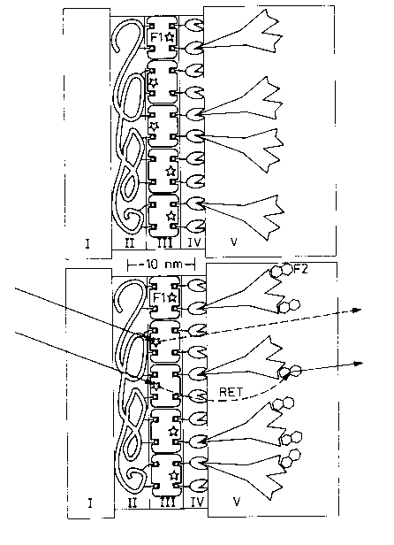
Figure 1 shows schematically, and approximately to scale, the multilayer construc-
tion of the test strips for the Forster energy transfer immunosensor (at the top),
and the detection principle (at the bottom).
Fi~ure 1: Schematic construction and function of the immuno-
sensor. The molecular components are drawn ~~
approximately to scale. The support I is much thicker
than shown.
At the top: Test strip, consisting of transparent support I (e.g. glass), a
polyelectrolyte multilayer II (for simplification of the figure
only the last biotinylated layer is shown), a layer of strepta-
vidin fluorescence-labeled with F1 III, a layer of biotinylated
protein A IV and the antibody V immobilized thereon.
At the bottom: After wetting with test liquid, the wavelength of the fluores-
cence observed depends, after excitation of the fluorescent
dye F1 coupled to streptavidin, on whether direct emission is
present (dotted arrow) or whether the excitation energy after
energy transfer (RET = dashed arrow) to the labeled analyte
is emitted with a red shift (full arrow). The ratio of red-
shifted to direct emission intensity is clearly dependent on
the number of bound analyte molecules per unit area.
Figure 2 shows X-ray reflectograms of the layer structure in various stages of
preparation.
Fi~ure 2: X-ray reflectograms of the layer structure (support
material: silicon) in various stages of preparation.
The various sets of data were in each case shifted by
a factor of 100 compared with one another. From the
bottom to the top, the curves show first the poly-
electrolyte multilayer, then the latter, coated with
streptavidin, subsequently still coated with bio-
tinylated protein A and f1nally provided with IgG
Le A 29 864-US 2 1 8 3 2 0 4
g
antibody. The pulse transfer Qz is plotted in ~~1 on
the abscissa and the X-ray intensity I on the ordinate.
The measurement shows for the present example that the surface is coated with aninterface layer of organic material grown regularly in the various preparation steps
5 and in each step the preparation remains smooth in molecular terms. This meansin particular that the surface functionalization does not lead to the coating of the
solid phase interface with laterally inhomogeneous structures, i.e. droplet forma- - ~
tion does not take place even on the nanometer linear scale.
Figure 3 shows the results of ELISA measurements on sensor surfaces which were
10 prepared analogously to the methods indicated in Figure 1 and recorded in
Figure 2 by means of X-ray reflectivity measurements.
Fi~ure 3: Titration of various sensor surfaces with antigen.
Specific binding was detected by means of ELISA. A
preparation in which IgG was adsorbed electrostati-
cally on a PSS layer (white diamonds) was compared
with a sensor which was prepared by the technique
described here (black diamonds). The antigen concen-
tration CAG in mol/l is given on the abscissa and the
optical density A at ~ = 414 nm on the ordinate.
20 Figure 4 shows the results of a biosensor measurement on a sample which was
prepared as the sample described in Figure 3.
Fi~ure 4: Titration of a sensor surface with antigen (black dia-
monds). Specific binding was detected by means of
energy transfer. The antigen was present in the
culture supernatant at about 2-fold dilution. Control
(white diamonds): antigen adsorption on a test Skip
which was only built up to the streptavidin layer
(without protein A and receptor layer). The abscissa
shows the concentration CAG in the culture super-
natant in mol/l. The ordinate shows the intensity ratio
of the fluorescences of the fluorescent dyes Fl and
F2 at 577 and 530 nm.
~- LeA29 864-US 21 83204
- 10 -
Examples:
1. Chemicals used
Polymers: Polystyrenesulfonate, sodium salt (PSS), MW = 70,000,
Aldrich
Polyallylamine hydrochloride (PAH), MW = 50,000 -
60,000, Aldrich
Polyethylenimine (PEI), MW = 50,000, 50 % strength --
solution in H2O, Aldrich
Poly-L-lysine hydrobromide (PL), MW < 50,000, Bachem-
I 0 Biochemica
The PSS was dialyzed against very pure water for two days in aqueous solution ina VISKING27/32 dialysis tube from Roth and then freeze-dried.
Proteins: Streptavidin, Boehringer-Mannheim
Protein A, Pharmacia
Rabbit IgG, polyclonal, specificity: anti-mouse IgG,
Immunol. Institute Univ. Mainz
Bovine Serum Albumin (BSA), Sigma
Antigens: Mouse IgG, monoclonal, culture supernatant, Immunol.
Institute Univ. Mainz
Horseradish peroxidase (HPO)-coupled mouse IgG, affinity
purified, Jackson Immuno-Research Laboratories, Dianova,
U.S.A.
Fluorophores: Rhodamine B isothiocyanate (RITC), Sigma
Fluorescein isothiocyanate isomer I (FITC), Sigma
25 The labeling of the streptavidin was on average 1.4 FITC per protein molecule and
that of the mouse IgG on average 3 RITC per protein molecule.
Biotin active ester: Biotinamidocaproyl-N-hydroxysuccinimide ester, Sigma
To biotinylate protein A, the active ester and the protein were weighed in a
molecular ratio of 12:1.
LeA29 864-US 21 83204
11 -
Detergent: Polyoxyethylene sorbitan monolaurate (TWEEN 20), Sigma
PBS buffer: Sodium dihydrogen phosphate, monohydrate, p.a., Merck
Disodium hydrogen phosphate, p.a., Merck
Sodium chloride, p.a., Merck
5Citrate buffer: Disodium hydrogen phosphate, p.a., Merck
Citric acid monohydrate, Sigma - - -
Potassium chloride, p.a., Merck
Magnesium chloride, hexahydrate, p.a., Merck
ABTS: 2,2'-Azino-bis(3-ethyl-benzothiazoline)-sulfonic acid, Sigma
Glass substrate: (38x12) mm2 and (1-1.2) mm thick microscope slide, Gebr.
Rettberg GmbH.
2. Cleaning of support
The support was cleaned according to a standard procedure (W. Kern,
D.A. Puotinen, RCA Review, 31 (1970), 187)
3. Preparation of support
All solutions were prepared using distilled water. The water-wetted supports were
placed in PEI solution (diluted to 2.2 mg/ml) for 30 minutes and then washed in
10 ml of water three times for about 30 seconds in each case and then blown dry
in a gentle stream of nitrogen. The sample was then placed in a PSS solution
(20 mg of PSS in 10 ml of a 2 M NaCl solution) for about 20 minutes and
washed and dried as described above. The support was placed in a PAH solution
(20 mg of PAH in 10 ml of 2 M NaCl solution) for a further 20 minutes and
again washed and dried. As described above, a further PSS layer, a PAH layer
and, in turn, a PSS layer were adsorbed on the support. For functionalization with
biotin, the support was placed in a solution of biotinylated polylysine hydro-
bromide (PLB) (5 mg/10 ml in 0.4 M NaCl) for 20 minutes and then washed and
dried again. The coated supports were stored at a temperature of 4C until use.
4. Building-up of the protein heteromultilayers:
PLB-coated supports were placed for about 30 minutes in an FITC-streptavidin
solution (10-7 mol/l of FITC-streptavidin in 10 mM PBS buffer, pH = 7.2,
Le A 29 864-US 21 83204
- 12 -
150 mM NaCl), washed three times with 10 ml of water and then placed for a
further 40 minutes in a solution of biotinylated protein A (5x10⁻⁷ mol/l, PBS
buffer as above) and washed three times with the pure PBS buffer. Drying steps
between the individual protein coatings were dispensed with. The support coated
5 with protein A was placed for 40 minutes in a rabbit IgG solution (specificity:
anti-mouse IgG, 5x10⁻⁷ mol/l, PBS buffer as above) and washed three times with
the pure buffer. Up to binding of the antigen, the support was stored in PBS
buffer. - -
Figure 2 shows X-ray refiectograms which were measured (dry sample) between
10 the various adsorption steps during the preparation of a test strip (support material
silicon). These results confirm that during the adsorption process a coherent layer
structure is formed which is uniform on a linear molecular scale, that the layerthickness increments in each case correspond to the molecular dimensions of the
absorbents and that the surface remains smooth in molecular terms after each
15 adsorption step. An exception is the terminal antibody layer, which because of the
elongated molecular form of the antibody and the regioselective binding by protein
A contains a high amount of aqueous buffer. This layer collapses in the drying
process during measurement and after this appears significantly thinner than is to
be expected from the molecular dimensions. The experimental data from Figure 2
20 are evaluated quantitatively in Table 1.
Table 1: Molecular dimensions of the active interface layer of the immuno-
sensor
Coating steps Layer Surface roughness
thickness org. interface/air (A)
increment (A)
6 molecular polyelectrolyte layers 203 6
(incl. PLB)
Streptavidin layer on polyelectrolyte 56 11
film/PLB
Biotinylated protein A on streptavidin 7 11
layer
Rabbit IgG (anti-mouse) on protein A 13 17
Le A 29 864-US 2 1 8 3 2 0 4
- 13 -
5. Incubation with antigen, including controls
a. ELISA measurements
Samples were prepared on silicon as described above. 10 mg/ml of BSA were
dissolved in PBS buffer containing 0.1 % TWEEN 20. This protein solution was
5 used for ELISA measurements for the preparation of a dilution series of the HPO-
labeled antigen (mouse IgG-HPO), whose concentration was between 10-l3 and
10-7 mol/l. After incubation with the antigen, the samples were developed in --
citrate buffer with 3 g/l of ABTS and 0.0075 % H2O2 and measured. Figure 3
shows a representative result for a preparation which was prepared by the techno-
10 logy presented here. Compared with this is the titration of a preparation in whichIgG was only adsorbed electrostatically on a silicon interface which was coated
with a thin molecular layer of PSS. The higher sensitivity, better linearity andlower nonspecific adsorption which distinguish the preparation prepared by the
new technique are clearly visible in the figure.
15 b. Fluorescence measurements
Samples were prepared on float glass as described above. 10 mg/ml of BSA were
dissolved in PBS buffer. This protein solution was used to prepare a dilution series
of the RITC-labeled antigen. In this dilution series, the concentration of the
antigen was between 2.5xlO-9 and 5x10⁻⁶ mol/l. The supports were placed for
20 about 40 minutes into the solution of a certain antigen concentration and then
washed 5 times for about 1 minute in a PBS buffer (buffer composition as above)
treated with 0.1 % TWEEN 20. The supports were blown dry in a stream of
nitrogen and stored in darkness at 4C until measurement.
To quantify the nonspecific interaction of the antigen with the substrate, supports
25 were coated in the same sequence up to and including the streptavidin layer (but
without protein A and IgG layers) and placed for about 40 minutes in an antigen-containing solution of the dilution series in each case and, as described above,washed and dried.
The sample and reference supports were measured both in a conventional
30 fluorescence spectrometer and a specially designed apparatus for the measurement
of fluorescence energy transfer in the dry state. Figure 4 shows representative
results.