Language selection

Search

Patent 2183229 Summary

Third-party information liability

Some of the information on this Web page has been provided by external sources. The Government of Canada is not responsible for the accuracy, reliability or currency of the information supplied by external sources. Users wishing to rely upon this information should consult directly with the source of the information. Content provided by external sources is not subject to official languages, privacy and accessibility requirements.

Claims and Abstract availability

Any discrepancies in the text and image of the Claims and Abstract are due to differing posting times. Text of the Claims and Abstract are posted:

  • At the time the application is open to public inspection;
  • At the time of issue of the patent (grant).
(12) Patent: (11) CA 2183229
(54) English Title: THREAD FEEDING BUFFER
(54) French Title: TAMPON D'ALIMENTRATION EN FIL
Status: Term Expired - Post Grant Beyond Limit
Bibliographic Data
(51) International Patent Classification (IPC):
  • B65H 51/20 (2006.01)
  • B65H 59/36 (2006.01)
(72) Inventors :
  • SAND, KJELL (Sweden)
(73) Owners :
  • APLICATOR SYSTEM AB
(71) Applicants :
  • APLICATOR SYSTEM AB (Sweden)
(74) Agent: MARKS & CLERK
(74) Associate agent:
(45) Issued: 2007-01-02
(86) PCT Filing Date: 1995-02-13
(87) Open to Public Inspection: 1995-08-17
Examination requested: 2001-12-19
Availability of licence: N/A
Dedicated to the Public: N/A
(25) Language of filing: English

Patent Cooperation Treaty (PCT): Yes
(86) PCT Filing Number: PCT/SE1995/000144
(87) International Publication Number: WO 1995021787
(85) National Entry: 1996-08-13

(30) Application Priority Data:
Application No. Country/Territory Date
9400490-0 (Sweden) 1994-02-14

Abstracts

English Abstract


A thread feeding buffer for feeding a fibre thread (15) from a
magazine roll (14) to a feed apparatus at a robot arm which is freely
movable in the room. The thread feeding buffer comprises thread
brake means (16, 19, 20) and at least one movable thread guide
(17), on which a thrust force is acting. The thread is running from
the magazine roll (14), via the brake means (16, 19, 20), through
the thread guide (17) and further on towards the feed apparatus in
such a way, that the thrust force acts for creation of a thread buffer
between the brake means and the feed apparatus, which buffer is
variable in length.


French Abstract

Tampon d'alimentation permettant de retirer un fil fibreux (15) d'un rouleau de stockage (14) et de le faire parvenir à un appareil d'alimentation au niveau d'un bras robotique pouvant se déplacer librement dans l'espace. Le tampon d'alimentation en fil comporte des organes (16, 19, 20) de freinage du fil, et au moins un élément mobile (17) de guidage du fil, cet élément étant soumis à une force de poussée. Le fil sortant du rouleau de stockage (14) s'étend jusqu'à l'appareil d'alimentation en passant par les organes de freinage (16, 19, 20) et l'élément de guidage (17), de telle sorte que la force de poussée crée un tampon de fil entre les organes de freinage et l'appareil d'alimentation, ce tampon étant de longueur variable.

Claims

Note: Claims are shown in the official language in which they were submitted.

5
The embodiments of the invention in which an exclusive
property or privilege is claimed are defined as follows:
1. A thread feeding buffer for a fibre thread fed from a
supply and along a path, the buffer comprising:
a first guide for the thread for receiving the thread
from the supply;
a contactable brake surface over which the thread is fed
from the first guide;
a brake element moveable into contact with the brake
surface for braking movement of the thread past the brake
surface;
a movable thread guide in the path of the thread past the
brake surface;
a support supporting the movable thread guide for
movement; and
a further guide following the movable thread guide in the
path of the thread and past which the thread is drawn;
the support enabling the movable thread guide to be moved
by the thread to reduce the length of the thread path
between the brake surface and the further thread guide upon
the brake element engaging the brake surface and also
permitting the movable thread guide to move to lengthen the
distance between the brake surface and the further thread
guide to absorb slack in the thread on the path between the
brake surface and the further thread guide.
2. The thread feeding buffer of claim 1, wherein:
the support supports the movable thread guide for
movement in the vertical direction so that the movable
thread guide is normally acted upon by gravity; and
the first guide and the further guide are both located
vertically above the movable thread guide so that the

6
movable thread guide can move up and down to absorb slack
in the thread.
3. The thread feeding buffer of claim 1 or 2, wherein the
brake surface comprises a runner over which the thread runs
and the brake element comprises a pneumatic cylinder and a
clamp movable with respect to the cylinder for clamping
against the brake surface.
4. The thread feeding buffer of any one of claims 1 to 3,
wherein the support comprises a generally vertically
oriented guide rod on which the thread guide is movable.
5. The thread feeding buffer of any one of claims 1 to 4,
wherein the first guide and the movable thread guide
respectively comprise eyelets through which the thread
passes.
6. The thread feeding buffer of any one of claims 1 to 5,
wherein the first guide and the further guide are
stationary, relative to the movement of the movable thread
guide.

Description

Note: Descriptions are shown in the official language in which they were submitted.


WO 95/2I787 PCT/SE95/00144
1
TITLE
Thread feeding buffer
FIELD OF THE INVENTION
The present invention is related to a thread feeding buffer
for feeding a fibre thread from a magazine roll to a feed
apparatus at a robot arm which is freely movable in the
room.
BACKGROUND OF THE INVENTION
The production of fibre reinforced thermosetting plastic
products can be automatized by the use of an industrial
robot, by means of which a fibre feed apparatus can be
controlled, so that precise amounts of fibres are fed out
which are oriented for maximum strength, without the fibres
projecting out through the outer plastic layer of the
product.
Owing to the repeatability of the robot, the quality of
these products can be increased considerably, simultaneously
as problems related to bad work environment and labour
fatigue can be solved.
The fibre feeding apparatus is preferably located in a
feedout head which can be mounted upon a movable robot arm.
One or more fibre threads are supplied to the feedout head,
which cuts the threads in suitable lengths. The feeding
speed of the fibre thread can be in the range of about 10
meters per second.
At such a feeding speed, it is difficult to stop the feeding
of thread without any risk of getting the thread tangled.

CA 02183229 2005-12-30
2
THE TECHNICAL PROBLEM
The object of~the invention is therefore to provide a thread
feeding buffer which solves the above described problems.
THE SOLUTION
For this object, the invention is characterized by thread
brake means and at least one movable thread guide on which
a thrust force is acting, and that the thread is running
from the magazine roll, via the brake means, through the
thread guide and further on towards the feed apparatus in
such a way, that the thrust force acts for creation of a
thread buffer between the brake means and the feed
apparatus, which buffer is variable in length.
Accordingly, in one aspect the invention provides a thread
feeding buffer for a fibre thread fed from a supply and
along a path comprising a first guide for the thread for
receiving the thread from the supply, a contactable brake
surface over which the thread is fed from the first guide,
a brake element moveable into contact with the brake
surface for braking movement of the thread past the brake
surface, a movable thread guide in the path of the thread
past the brake surface, a support supporting the movable
thread guide for movement, and a further guide following
the movable thread guide in the path of the thread and past
which the thread is drawn, the support enabling the movable
thread guide to be moved by the thread to reduce the length
of the thread path between the brake surface and the
further thread guide upon the brake element engaging the
brake surface and also permitting the movable thread guide
to move to lengthen the distance between the brake surface
and the further thread guide to absorb slack in the thread
on the path between the brake surface and the further
thread guide.

CA 02183229 2005-12-30
2a
BRIEF DESCRIPTION OF THE DRAWINGS
The invention will naw be described in the following, with
reference to an embodiment which is shown schematically on
the accompanying drawing, in which
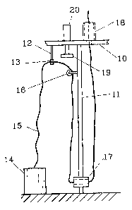
Fig. 1 is a plane view of a thread feeding buffer
according to the invention, and
Fig. 2 shows the thread feeding buffer in Fig. 1 in
a side view_
DESCRIPTION OF PREFERRED EMBODIMENTS
The thread feeding buffer according to the drawing comprises
a stand 10 with two vertical guide rods 11. The stand 10
carries an elbow arm 12 with a thread eyelet 13 for a thread
which is wound off from a roll 14. The thread can consist
of a multiple fibre thread of glass, carbon fibre or
15 synthetic fibre. The thread eyelet 13 provides for a
substantially.friction free passage of the thread.
The thread runs upwards from the roll 14 which is located at
ground level, through the thread eyelet 13 and further over
a bar 16 which changes the direction of pull back vertically
down between the guide rods 11. A thread guide 17 is movably
guided by the guide rods and is provided with further thread

WO 9512fl787 PCTJSE95I00144
3
eyelets 13, through which the thread 15 runs. Then the
thread runs on from the thread guide 17 in the direction
upwards to a thread guide channel 18, which guides the
thread further to a not shown robot arm.
A thread brake cooperates with the bar 16 and is composed of
a clamp plate 19, which is mounted at the outer end of a
pneumatic cylinder 20 which is connected to the stand 10.
The clamp plate can be brought in or out of engagement with
the bar 16 by operation of the cylinder 20, whereby the
feeding of the thread will be stopped.
The thread feeding buffer operates in the following way:
During normal thread feeding, the pulling of the thread, via
the thread eyelets 13 and the bar 16, creates an even
resistance in the thread which results in an advantageous
even outfeed. If the robot arm is moving in the room, so
that more or less thread has to be fed out momentarily, the
thread guide 17 will be able to move up and down
respectively along the guide rods, wherein the thread will
receive a rapid compensation in length.
If the feeding of the thread is to be stopped, this is made
by activation of pneumatic cylinder 20 which then presses
the clamp plate 19 against the bar 16. Now the feeding of
thread at the end of the robot arm will continue for s short
moment while the thread guide 17 moves upwards along the
guide rods 11, until the pull in the thread is stopped. When
it will be time for restarting the feeding, this will be
commenced with a correctly pretensioned thread without the
risk of loops or kinks on the thread.
The invention is not limited to the above described
embodiment, but several variations are possible within the
frame of the accompanying claims. For example, the guide
rods can be exchanged for other means for controlling a

R'O 95121787 PCTISE95100144
4
buffer of fibre thread. Further, a spring means can replace
the action of gravity upon the thread guide means 17.

Representative Drawing
A single figure which represents the drawing illustrating the invention.
Administrative Status

2024-08-01:As part of the Next Generation Patents (NGP) transition, the Canadian Patents Database (CPD) now contains a more detailed Event History, which replicates the Event Log of our new back-office solution.

Please note that "Inactive:" events refers to events no longer in use in our new back-office solution.

For a clearer understanding of the status of the application/patent presented on this page, the site Disclaimer , as well as the definitions for Patent , Event History , Maintenance Fee  and Payment History  should be consulted.

Event History

Description Date
Inactive: Expired (new Act pat) 2015-02-13
Inactive: Office letter 2014-05-01
Inactive: Reversal of will be deemed expired status 2014-05-01
Letter Sent 2014-02-13
Maintenance Request Received 2013-01-23
Inactive: Office letter 2010-03-15
Inactive: Payment - Insufficient fee 2010-02-23
Inactive: Office letter 2007-01-26
Inactive: Corrective payment - s.78.6 Act 2007-01-18
Grant by Issuance 2007-01-02
Inactive: Cover page published 2007-01-01
Pre-grant 2006-10-18
Inactive: Final fee received 2006-10-18
Letter Sent 2006-05-15
Notice of Allowance is Issued 2006-05-15
Inactive: Approved for allowance (AFA) 2006-02-28
Amendment Received - Voluntary Amendment 2005-12-30
Inactive: S.30(2) Rules - Examiner requisition 2005-07-19
Amendment Received - Voluntary Amendment 2003-01-13
Inactive: Application prosecuted on TS as of Log entry date 2002-03-12
Letter Sent 2002-03-12
Inactive: Status info is complete as of Log entry date 2002-03-12
Inactive: Entity size changed 2002-02-14
All Requirements for Examination Determined Compliant 2001-12-19
Request for Examination Requirements Determined Compliant 2001-12-19
Application Published (Open to Public Inspection) 1995-08-17

Abandonment History

There is no abandonment history.

Maintenance Fee

The last payment was received on 2006-02-01

Note : If the full payment has not been received on or before the date indicated, a further fee may be required which may be one of the following

  • the reinstatement fee;
  • the late payment fee; or
  • additional fee to reverse deemed expiry.

Please refer to the CIPO Patent Fees web page to see all current fee amounts.

Owners on Record

Note: Records showing the ownership history in alphabetical order.

Current Owners on Record
APLICATOR SYSTEM AB
Past Owners on Record
KJELL SAND
Past Owners that do not appear in the "Owners on Record" listing will appear in other documentation within the application.
Documents

To view selected files, please enter reCAPTCHA code :


To view images, click a link in the Document Description column. To download the documents, select one or more checkboxes in the first column and then click the "Download Selected in PDF format (Zip Archive)" or the "Download Selected as Single PDF" button.

List of published and non-published patent-specific documents on the CPD .

If you have any difficulty accessing content, you can call the Client Service Centre at 1-866-997-1936 or send them an e-mail at CIPO Client Service Centre.


Document
Description 
Date
(yyyy-mm-dd) 
Number of pages   Size of Image (KB) 
Representative drawing 1997-09-17 1 6
Cover Page 1995-02-13 1 14
Claims 1995-02-13 1 24
Abstract 1995-02-13 1 46
Drawings 1995-02-13 1 15
Description 1995-02-13 4 126
Description 2005-12-30 5 158
Claims 2005-12-30 2 60
Claims 2002-04-10 1 29
Drawings 2005-12-30 1 14
Representative drawing 2006-02-28 1 5
Cover Page 2006-11-28 1 35
Description 2007-01-01 5 158
Abstract 2007-01-01 1 46
Reminder - Request for Examination 2001-10-16 1 129
Acknowledgement of Request for Examination 2002-03-12 1 180
Commissioner's Notice - Application Found Allowable 2006-05-15 1 162
Notice of Insufficient fee payment (English) 2010-02-23 1 93
Correspondence 1996-11-05 1 41
PCT 1996-08-13 10 392
Correspondence 2006-10-18 1 28
Correspondence 2007-01-26 1 13
Fees 2008-02-06 1 32
Fees 2009-02-11 1 30
Fees 2010-02-09 3 87
Correspondence 2010-03-15 1 16
Fees 2010-02-09 1 35
Fees 2011-01-24 1 36
Fees 2012-01-26 1 35
Fees 2013-01-23 1 30
Correspondence 2014-05-01 1 15
Fees 1997-01-27 1 61