Note: Descriptions are shown in the official language in which they were submitted.
WO 96/19890 218 3 3 4 4 p~~S95/13678
METHOD AND SYSTEM FOR CONTROLLING
ACCESS TO A C~ iANNEL
Field of the Invention
The present invention relates generally to the field of
communications and more particularly to cable telephony.
Background of the Invention
A goal of the information super-highway is to combine
telephony, video and data signals over the same cable. Cable television
(CATV) operators have an existing high bandwidth cable network to
the house or premise which could carry these diverse services. Several
cable telephony systems have been proposed. A goal of any cable
telephony system is to be backwards compatible with the existing
telephony system. This requires that a subscriber to a cable telephony
system be able to plug their existing telephone into the cable telephony
system and have it operate in the same manner. This simple
requirement poses a number of challenges to the cable telephony
designer. Existing telephones are powered through the telephone line,
as opposed to premise powered like a television. This provides a so
called lifeline feature that allows a subscriber to make an emergency
telephone call even when the premise power is down.
Existing telephone service, some~nes known as plain old
telephone servire (POTS), requires the operator to provide loop
current, or at least twenty four volts DC at twenty five milliamps,
when the subscriber's telephone is in an off hook state. If you multiply
this by the potential number of subscribers in a cable telephony system
this adds up to a major power management problem. This problem is
especially acute because existing cable television systems do not ha ve to
provide power for any subscriber equipment and therefore are not
designed to handle this sort of power distribution problem.
Another problem in providing POTS over a cable is that the tip
and ring signal is converted to a radio frequency (RF) signal. This
wo 96n9s9o 218 3 3 4 4 p~T~s9sn~s~s
2
requires at minimum a RF transceiver with processing capabilities.
Most of the time the telephone is idle, waiting for an incoming call.
Monitoring for an incoming call in a cable telephony system requires
the RF transceiver to be monitoring the channels continuously. To
provide the lifeline feature discussed above the RF transceiver must
also be powered by the cable and is thus constantly draining power in
the idle mode.
The present cable power system cannot provide the necessary
power required for this idle mode and would fail if a large number of
subscriber's telephones went off-hook all at the same time. One
solution is to increase the voltage at the headend of the cable system to
provide adequate power at the subscriber's premise. This approach
suffers from several drawbacks. One, the voltage at individual
subscriber's premises would vary widely, since many of the power
drains in a cable system are in series. Thus, it would require a complete
redesign of the cable system to assure the voltages at the various
subscriber premises were within operating voltages of the equipment
providing POTS to the subscriber.
Another solution would be to completely redesign the power
distribution system of existing cable systems. This would be extremely
expensive and disruptive of the present television service provided by
cable operators.
A third solution is have premise powered telephones with
battery backup for emergencies. This does not meet the goal of having
the cable telephony system backwards compatible with the existing
telephones. It also creates a disposal problem and a management
problem.
For the reasons listed above, each of the solutions to the
problem of providing the power required for POTS service in a cable
system has drawbacks. Thus, there exists a need for a method and
system to provide cable power POTS.
WO 96/19890 2 ~ g 3 3 4 4 PCTNS95I13678
3
Brief Description of the Drawings
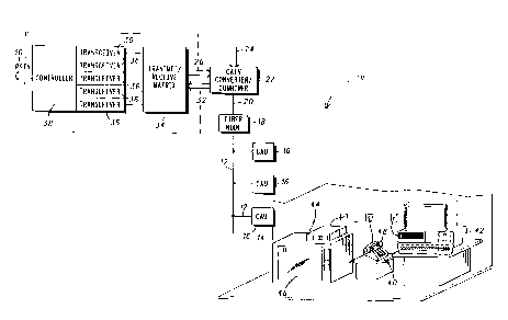
FIG. I is a block diagram of a cable telephony system;
FIG. 2 is a graphical diagram of the frequency band of a cable
telephony system;
FIG. 3 is graphical diagram showing the division of a broadcast
television band into a number of telephone bands;
FIG. 4 is a graphical diagram of the time division multiplexing of
the telephone bands;
FIG. 5 is a block diagram of a cable access unit;
FIG. 6 is a graphical representation of a system broadcast channel;
FIG. 7 is a -graphical representation of an alert phase;
FIG. 8 is a flow chart of a process used by a cable access unit while
waiting to rereive an incoming telephone call;
FIG. 9 is a flow diagram of a process used by a cable control unit
to determine when a charnel is available;
FIG. 10 is a flow diagram of a process used by a cable access unit to
determine if a channel is available;
FIG. 11 is a flow chart of an alternative proress used by a cable
control unit to determine when a channel is available; and
FIG.12 is a flow diagram of an alternative proress used by a cable
access unit to determine if a channel is available.
Description of the Preferred Embodiments
For the reasons stated above) it is necessary to reduce the power
consumption of plain old telephone service (POTS) in a cable
telephony system to provide standard line powered telephone service.
In order to understand how power consumption is reduced, it is
helpful to first understand how telephony can be implemented over a
coaxial cable.
FIG.1 is a block diagram of a cable telephone system 10. A
coaxial cable 12, for instances a standard cable television (CATV) cable,
connects to a house or premise 14 through a cable access unit 16 on the
side of the house 14. The coaxial cable 12 carries both broadcast
wo 96n9s9o 218 3 3 4 4 PCTIUS95/13678
4
television signals and telephone signals. All of the cable access units
(CAUs) 16 connect through the cable 12 to a fiber node 18. The fiber
node 18 converts the optical signals on a fiber optic cable 20 to electrical
signals carried by the coaxial cable 12 and the electrical signals to optical
signals. The fiber optic cable 20 connects to a CATV converter and
combiner 22, that combines a CATV signal or television broadcast
signals 24 and a plurality of telephone signals 26 from a cable control
unit (CCU) 28. The CATV converter combiner 22 strips off the
telephone signals coming from the house 14 and headed to a public
switched telephone network (PSTN) 30. When the term PSTN is used
in this application it is meant to broadly refer to any telephone or data
network other than the cable telephony system of this application.
These upstream telephone signals connect to the CCU 28 through a
signal line 32. The CCU 28 has a transmit/receive matrix 34 which
connects the telephone signals to an appropriate channel transceiver
36. The transceivers 36 are connected to a rnntroller 38 that interfaces
with the PSTN 30.
The CAU 16 connects a wide variety of devices to the plurality of
channels carried by the cable 12. These devices include a standard
telephone 40, a computer 42, and a set top box 44 for a television 46. To
place a telephone call a subscriber or user would pick up a receiver 48 of
the telephone 40. This places the telephone 40 in an off-hook state
which is detected by the CAU 16. The CAU 16 then requests a channel
from the CCU 28. The CCU 28 assigns a channel to the CAU 16 after
which the telephone call proceeds essentially in the same manner as a
standard telephone call. The CAU 16 has to request a channel from the
. CCU 28 because the telephone service is franked, which means a
channel is not dedicated to a particular CAU 16 (or house) but are held
in common by the system and assigned when needed by the CAUs 16.
This allows the CCU 28 to have fewer channels than there are CAUs 16.
For instance, there, may be one thousand CAUs 16 with telephone
subscriptions and only one hundred channels 36. A franking system
works because most subscribers only use their telephones 40 a very
small amount of time. Since, not all the subscribers will normally be
engaged in a telephone call at once, the system can have fewer
WO 96/19890 PCT/US95/13678
283344
channels than subscribers and still provide instant access to the
telephone system the majority of time.
When there is a call coming into a subscriber of the system 10
the CCU 28 will send out an alert to the appropriate CAU 16 on a
5 system broadcast channel that a call is waiting. When the CAU 16
receives the alert it responds with an acknowledgment and is directed
to the appropriate channel by the CCU 28. From there on a standard
telephone call ensues.
In the preferred embodiment, the telephony system 10 is a
frequency/time division multiple access system (FTDMA). The
telephony system is designed to coexist with broadcast television
signals on the same coaxial cable and fit within the existing CATV
system. FIG. 2 shows the frequency band of a typical CATV system. The
CATV system defines the acceptable frequency bands for signals as
running from 5 to 750 Nmz. A television channel 60 occupies 6 MHz of
spectrum in a downstream frequency band 62, which runs from 50 MHz to
750 MHz~An upstream frequency band 64 runs from 5 MHz to 42 MHz.
In the preferred embodiment, the telephony system occupies at least
one 6 MHz downstream television channel 60 and a plurality of 600 KHz
upstream bands. The television channel 60 is divided up into a
number of six hundred KHz telephone bands 66, see FIG. 3. Each six
hundred KHz telephone band 66 is divided into a plurality of time slots
68, see FIG. 4. Each time slot 68 defines a telephone channel 34. At least
one downstream telephone channel is dedicated to control
information carried by a system broadcast channel, see FIG. 6 for more
detail.
An important goal for a cable telephony system is to provide
telephone service that is backwards compatible with the existing
telephone service or Plain Old Telephone Service (POTS). This means
that subscribers to a cable telephone service must be able to use their
present telephones 40 with the new service. One of the important
features of the present telephone service is that the telephone 40 is
usable even when the subscriber's house 14 or premise loses power.
This so called lifeline feature either requires battery backup with
premise powering of the telephones 40 or power to be provided by the
WO 96/19890 PCT/US95/13678
6 21 8334 4
cable I2 which carries the telephone signals. Battery backup requires a
large number of batteries that have to be replaced periodically. Creating
a disposal problem and a management problem.
To understand the difficulties in providing cable 12 powered
POTS in a cable telephony system 10 it is helpful to first examine how
the CAU 16 operates. The CAU 16 is shown in FIG. 5. The cable 12
enters the CAU 16 and is connected to a DC power supply 100 to power
the telephone 40 and the other POTS required equipment in the CAU
16. A capacitor or filter 102 blocks the low frequency, sixty hertz, power
supplied by the cable 12 from the RF circuitry. A duplexer I04 connects
to the capacitor 102 and splits the downstream frequency band 62 from
the upstream frequency band 64. A downstream signal 108 connects to
a bandpass filter 110. The bandpass filter I10 passes frequencies in the
downstream frequency band 62. The downstream signal is then
divided into two paths by a sputter 112. One path connects to all the
non-POTS services provided over the cable 12. The other path
connects to a TDMAtransceiver 114 that makes up part of the POTS
service.
The upstream path connects from the duplexer 104 to a filter I16
that passes the upstream frequency band 64. The filter 116 connects to
the TDMA transceiver 114, which is controlled by a microprocessor 118.
The TDMA transceiver lI4 connects to a data converter 120. The data
converter 120 takes an analog tip and ring telephone signal 122 from
the POTS telephone 40 and converts the telephone signal 122 to a
digital TDMA format for transmission over the cable 12. The data
converter also takes the received TDMAdata from the TDMA
transceiver 114 and converts the signal to the analog tip and ring
telephone signal 122. In the preferred embodiment, the data converter
120 is implemented in an application specific integrated chip (ASIC).
As explained above, an important feature of the cable telephony
system 10 is to provide POTS. To provide POTS it is necessary to .
provide at least twenty four volts direct current (DC) between the tip
and ring Lines of the telephone 40. This is accomplished by providing
sixty hertz power over the cable 12. Presently, POTS telephones 40
connect to the outside telephone lines through an Rj11 connector 123.
A
WO 96/19890 PCT/US95/13678
218~3~4
Also the standard telephone 40 requires a radio frequency transceiver
and associated circuitry in order to communicate over the cable 12.
Which is shown in FIG. 5 as theTDMA tra~ceiver 114 and
microprocessor I18 and data converter I20. All these components
must be powered from the cable I2, to provide POTS service. Thus, the
power supply 100 supplies power to the microprocessor 118, the TDMA
transceiver I14 and the data converter I20 and the tip and ring lines
I22. A switch 124, controlled by the microprocessor 118, gates the
power being applied to the tip and ring lines 122.
Power is consumed by the CAU 16 in two different modes. One
mode is when a subscriber is attempting to place a telephone call. In
this case the subscriber picks up the receiver 48 which requires the
power supply 100 to provide twenty four volts DC at twenty five n-
dlliamps or loop current to the telephone 40. When the subscriber
wishes to place a call the microprocessor 118 sends a message to the
CCU 28 over the transceiver I14 requesting access to one of the trunked
channels. Once the telephone call has been established by the
microprocessor I18, the data converter I20 and the TDMA transceiver
114 all require power for the telephone call to occur.
The second mode that consumes power in the CAU 16, occurs
when the telephone 40 is idle waiting for an incoming phone call. This
requires the transceiver 114 and microprocessor 118 to monitor a
systems broadcast channel (SBC) 200, see FIG. 6. The SBC 200 transmits
control information and is divided up into alternating alert phases 202
and system information blocks 204. There are N alert phases 202 that
repeat periodically. The information in each alert phase 202, see FIG. 7,
includes an alert phase header 210, an alert phase ID 212, a super frame
interval (SFI) or frame interval 214, a line power limiting (LPL) status
flag 216, and a plurality of alert values or alert flags 218. The alert phase
header 210 notifies the CAUs 16 that the information to follow is alert
phase 202 information. The alert phase ID 2I2 defines which alert
phase 202 is presently being broadcast. The SFI 214 defines how long it
will be until this alert phase occurs again. The LPL status flag 216 will
be discussed in detail later. The alert value 218 is a unique identifier,
which alerts the associated CAU 16 that there is an incoming call.
:;
~'i
WO 96/19890 PCT'/US95/13678
218334
Statistically, most of the time the telephone 40 is in the second mode
waiting for an incoming telephone call. As a result, a major power
drain on a telephone system is the power consumed in this mode. To
reduce this power consumption the CAUs 16 in the cable system 10 are
divided into N groups corresponding to the N alert phases 202. The
CAUs 16 in the first alert phase 202 will only receive notification, via
broadcast of their unique alert value 218 over the SBC 200, during the
first alert phase 202. As a result, the transceiver 114 and microprocessor
118 only need to be on when waiting for a call during their CAUs
I6 alert phase 202. This reduces the power consumption in this second
mode by about I/N. If there are 100 alert phases 202 this results in a
significant savings in system power.
A flow diagram of the process used in the CAU 16 is shown in
FIG. 8. After the process starts 230, the CAU 16 determines, at step 232,
ff a sleep timer is equal to or less than zero. If the timer is not less than
or equal to zero, the process waits until the timer is equal to zero. If the
timer is less than or equal to zero the transceiver lI4 is powered up, at
step 234. Then the CAU 16 determines, in step 236, if its unique alert
value 218 has been received. If its unique alert value 218 has been
received, an incoming telephone call is received, at step 238. If its
unique alert value 218 is not received, the sleep timer is set, at step 240,
to the SFI 214. Next, the power is turned off, at step 242, to the
transceiver 114. The process then begins over at step 232. This process
makes up the first subsystem which controls both power consumption
in the CAU 16 and channel access.
In the first mode, where a telephone call is placed by the
subscriber, the biggest power drain is the twenty four volts DC at twenty
five miIhamps that must be supplied to the telephone 40. Because the
cable telephony system 10 is trunked, the system might, for example,
only be capable of handling one hundred simultaneous telephone calls
even though there are one thousand telephones 40 serviced by the -
system 10. Since the power drain by the telephones 40 in the off-hook
mode is substantial, it makes sense to size the overall system power
budget so only a few telephones 40 more than one hundred can be
powered in the off-hook mode at any one time. This is accomplished
A
WO 96/19890 PC'T/US95/13678
218334
by having the CCU 28 monitor the number of transceivers 36 in use
and sending out a status flag ff the number of transceivers 36 in use is
near the total number of transceivers 36. The CAUs 16 receive this
status flag and open the switch 124 which supplies power to the
telephone 40. Which prevents the system 10 from having to supply
power to the telephones 40, when no channel is available to place a
telephone call.
This process, as applied by the CCU 28, is described in more
detail in FIG. 9. First the CCU 28 determines, in step 250, the number of
channels in use. Next, the CCU 28 determines, in step 252, if the
number of channels in use exceeds a first predetermined number. If
the number of channels in use does exceed a first predetermined
number, the LPL status flag 216 is set, in step 254, to full. If the number
of channels in use does not exceed a first predetermined number,
processing returns to step 250. After the status flag 216 is set to full, the
CCU 28 determines, in step 256, ff the number of channels in use is less
than a second predetermined number. In the preferred embodiment,
the second predetermined number is less than the first predetermined
number. This adds a hysteresis to the system channel capacity. Until
the number of channels in use is less than a second predetermined
number, processing stays at step 256. When the number of channels in
use is less than a second predetermined number, a maximum wait
time is set at step 258. Then, the LPL status flag 216 is set, at step 260, to
available. Processing then returns to step 250.
FIG. 10 describes this process as implemented by the CAU 16.
The CAU 16 monitors, at step 270, the system broadcast charmeI. Next,
the CAU 16 determines, at step 272, if the LPL status flag 216 is set to
full. If the LPL status flag 216 is not set to full, then processing returns
to step 270. If the LPL status flag is set to full, then the CAU 16 opens, at
step 274, the telephone power switch 124. Next, the CAU 16 monitors,
' at step 276, the SBC. At step 278, the CAU 16 determines if the LPL
status flag 216 has been set to available. If the LPL status flag 216 has
' not been set to available, then processing returns to step 276. If the LPL
status flag 216 has been set to available, then the CAU 16 receives, at
step 280, a maximum wait time. Next the CAU 16, calculates, at step
A
WO 96/19890
-- PCT/US95/13678
l0 21 8334 4
282, a random time between zero and the maximum wait time. A
timer is started at step 284. Then the CAU 16 determines, at step 286, if
the timer is greater than or equal to the random time. If the timer is
not greater than or equal to the random time, then processing waits at
step 286 until the timer is greater than or equal to the random time.
Once the timer equals or exceeds the random time, the CAU 16 closes,
at step 288, the telephone power switch 124. Processing then returns to
step 250. This process describes the second subsystem that is designed
to deal with the loop current power problem resulting from too many
telephones 40 being in the off-hook mode.
An alternative embodiment of this process, uses a
deterministic, queuing system that does not close the telephone power
switch I24 until the CCU 28 has determined a tele hone
p channel is
available for the CAU 16 and associated telephone 40. As a result, the
maximum number of telephones 40 drawing off-hook power, twenty
four volts DC at twenty five milliamps, at any one time is equal to the
total number of telephone channels.
This process, as applied by the CCU 28, is described' in more
detail in FIG. 11. First, the CCU 28 determines, at step 300, if the CAU
16 is requesting a telephone channel. If no CAU 16 is requesting a
telephone channel, then processing waits at step 300. Once the CAU 16
requests a channel, the CCU 28 determines, at step 302, if the number of
channels in use exceeds a predetermined number. If the number of
channels in use does not exceed a predetermined number, then the
CCU 28 assigns, at step 304, a channel to the CAU I6 and processing
returns to step 300. If the number of channels in use exceeds a
predetermined number, then the CCU 28 assigns, at step 306, the CAU
16 the next priority number (PN). The priority number would be one if
the CAU I6 were the first to request a channel after all the channels
were full. Thus, priority numbers set up a queue for channels as they
become available. Next, the CCU 28 determines, at step 308, if the
number of channels in use exceeds a predetermined number. If the
number of channels in use exceeds a predetermined number, the CCU
28 determines, at step 310, if the CAU I6 is requesting a channel. If a
CAU 16 is requesting a channel, then processing returns to step 306,
A
WO 96/19890 PCT/US95/13678
11 29 8334 4
where a priority number is assigned. If a CAU 16 is not requesting a
channel, then processing returns to step 308. If at step 308, the number
. of channels in use does not exceed a predetermined number, then the
CCU 28 assigm, at step 312, the CAU 16 with the priority number of one
a channel and the priority numbers are all decremented by one. Next,
the CCU determines, at step 314, if the highest priority number is equal
to zero. If the highest priority number is not equal to zero, then
processing returns to step 308. If the highest priority number is equal to
zero, then processing returns to step 300.
This process, as implement by the CAU 16, is described in
more detail in FIG. I2. The process begins with the CAU 16
determining, at step 320, if the telephone 40 is off-hook. If the
telephone 40 is not off-hook, the CAU 16 waits until the telephone 40 is
off-hook. Next, the CAU 16 requests, at step 322, a telephone channel.
Then the CAU 16 waits, at step 324, until a channel is assigned. Once a
channel: is assigned the CAU 16 closes, at step 326; the telephone power
switch 124. Then the CAU 16 waits, at step 328, until the phone call has
ended. Once the telephone call has ended, the CAU 16 opens, at step
330, the telephone power switch 124. Processing then returns to step
320.
In summary, the present invention provides a method and
system for controlling power consumption and access to telephone
channels in a cable telephony system. This, accomplished with two
subsystems, one for limiting power and access when the telephone
is waiting to receive a telephone call and a second for limiting power
and access when a subscriber wants to place a call. A telephone is
usually in the first mode, waiting for a telephone call. The first
subsystem reduces power consumption by having the RF TDMA
transceiver for the POTS telephone only monitor for incoming calls
periodically and turns off the transceiver when not monitoring for
calls. The second subsystem, limits system power consumption and
telephone channels by only allowing loop current and access to
channels when a channel is available for use. These two subsystems
significantly reduce the overall system power consumption and
regulate access to the telephone channels. Using this system allows
~,4
WD 96119890 ?_ 18 3 3 ~ 4 PCT/US95I13678
12
existing cable operators to provide POTS service without expensive
changes to their existing power distribution network.
While the invention is described with respect to the power
distribution problem associated with providing POTS in an existing
cable system, the invention hag applications beyond this problem. For
instanre, the invention can be used to regulate the access to a limited
number of telephone channels or to a limited number of data
channels. For those skilled in the art many other alternatives,
modifications and variations will be obvious. For instances, the
invention is described with respect to FTDMA telephony channels,
however the telephony channels could be code division multiple
acress (CDMA). Accordingly, it is intended to embrace all such
alternatives, modifications and variations as fall within the spirit and
broad scope of the appended cleans.