Note: Descriptions are shown in the official language in which they were submitted.
, . `. `, .'
`. 21 ~3423
WO 95/22425 PCT/EP95/00547
Desc.i~,lion
Milling Cutter
The invention relates to a milling cutter having the features of the preamble to Claim 1.
In a prior art milling cutter d;.closed in DE 40 03 862 A1 of the type ",enlioned at the
beginning, the support bodies equipped with cutting plates lie individually in recesses
made from the end face of the base body b~sir~lly parallel to its longitudinal axis or to the
axis of r~lalion of the milling cutter. In each recess, the support bodies are tensioned
radially outwards against the wall of the recess by means of clamping devices that can be
activated by the end face of the base body. This ensures a secure support against the
centrifugal forces being exerted on the support bodies during operation. The recesses for
the insertion of the support bodies must be bored or cut individually. This makes the
milling cutter very co"~plic~ted and costly to manufacture. Furthermore, the recesses for
the insertion of the individual clamping devices must be widened on one side. This is
because the clamping devices used here are clamping wedges, and the further steps for
their arrangement require more co" ,-~c~ted production steps.
The object of the invention is to create a milling cutter of the type mentioned at the
beginning having radial support for the support bodies against the centrifugal forces
exerted, which milling cutter is easy to manufacture without cori,pro". ing on its
fu. ,ctioni. ,g. This objective is attained through the combination of features in Claim 1.
The solution in accor.lance with the invention enables the central area, the peripheral
area and the step formed between them to be easily completed in a single tensioning
procedure. The same applies for the mounting plate, and the support bodies are also
easy to manufacture. The milling cutter is therefore characterized by a particularly high
degree of axial and concentric accuracy, due to the fact that the support body beddings
are manufactured in the same tension;ng procedure and therefore in one cut, so to speak.
This procedure produces both the base as well as the bearing surfaces for all support
bodies, i.e. for the cutting plates.
-` 2183423
WO 9~;/22425 PCT/EP95/OOS47
Due to their radial direction, the grooves of the mounting plate can be made precisely,
with few notches in the stress direction, and relatively inexpensively by means of e.g. wire
EDM.
Manufacture is made even simpler through the desiyl ,s in accordance with Claim 2.
Through the special design in accordance with Claim 3, howevcr, the basic design of
peripheral area, central area and the step of the base body as well as of the opposite
area of the mounting plate can be machined by rotation. Surface and cylindrical yli"din9
of the surfaces of the base body and the mounbng plate is then possible in a simple
manner, which surfaces are ple~ol",ed through the rotation process and which operate
together.
Claim 4 ensures a particularly secure tensioning of the support bodies against the base
body. This tensioning provides for a higher degree of shHting security for the support
bodies in the direction of the base body axis.
Claim 5 ensures a largely planHorm bearing of the support bodies on the base body. This
effect is further improved through Claim 6.
Claim 8 creates a largely planifomm bearing of the support body on the base body which is
also effective radially outwards against the centrifugal force.
The basic structural components allow for a simple screw tensioning of the support
bodies in accG,dance with Claim 9.
Claim 10 has the effect of evenly tensioning the support body against the base body.
Claim 11 is based on the presupposibon that, in order to simplify manufacture of the
support bodies, the cufflng plates are arranged with their face appruxi"~ately parallel to
the support bûdy flanks. Claim 11 then results in a positive effective cutting angle, which
favors chip formation and chip removal to the cutter axis and out of the cutting area of the
cutting plates. This is of particular relevance for milling cutters driven at a high peripheral
speed.
21 83423
WO 9~/22425 PCT/EP95/00547
Through Claim 12, the cenleri"g of the mounting plate against the base body is simplified
and is automatically performed in assembly.
Claim 13 allows the annular pro;ection to be produced in a particularly simple manner in
one roldllng procedure.
Claim 14 results in an extremely small distdnce between the end face of the cuKer body,
formed here through the mounting plate, and the work piece, with the result that no chips
accumulate here, or a low air volume can be used to create a high air pressure, which is
advantageous for radially blo~ g out the chips from the peripheral region of the milling
cutter.
Claim 1~ supports the fault-free removal of the chips.
Through Claim 16, the entire, multi-piece cutter body has a uniform effective diameter.
This increases the emciency of chip ~u'lectiQn within and chip removal out of the
peripheral region of the milling cutter. Due to the unifomm effective diameter, the milling
cutter can be easily used in combination with a collection device for the chips.
Through Claim 17, chip spaces for the direct collection and removal of chips can be
ar,anged at a particulariy e~ri-,;cnl posilion in the vicinity of the cutting plate edges in the
operating position. In combination with the available centrifugal forces, this automatically
sucks up the chips in the peri~ herdl direction.
Claim 18 allows for a particularly vibldlion-free connection betueen the mounting plate
and the base body.
Through Claim 20, the support bodies are effectively supported in a planiform manner
against the three cutting-pressure components operdling on them, wherein the additional
clamping-flank support ensured here operates against the particularly significant main
cutting pressure.
In accor~ance with Claim 21, the support bodies are additionally supported against the
centrifugal force operating on them by means of the mounting-plate grooves.
21 83423
,
WO 95/22425 PCT/EP9S/00547
The invention is explained in greater detail with an exemplary embodiment shown in the
figures. This shows:
Fig. 1 a main side view - pallic.,ly in cross-section - of the milling cutter appro3ti",dlely
along the cross-section line I - I in Fig. 3,
Fig. 2 a diametrical section along the cross-section line ll - ll in Fig. 3,
Fig. 3 a top view of the lower worhi"g end of the milling cutter in the viewing direction
from arrow lll in Figs. 1 and 2,
Fig. 4 a top view of the mounbng plate forming the wo,king end of the milling cutter,
also in the viewing di~e~.tion from arrow lll in Figs. 1 and 2,
Fig. 5 a side view - partially in cross-section - of the milling cutter circumference in the
region of a support body equipped with a cutting plate, approxil.,ately in the
direction of arrow V of Fig. 3,
Fig. 6a a magnified cross-sectional view of the peripheral-side end of the base body in
area Vl of Fig. 1,
Fig. 6b a magnified illu:,l,alion of the support body, equipped with a cutting plate and
tensioned on the base body, of area Vl from Fig. 1,
Fig. 7 a schematic top view of a support body equipped with a cutting plate with the
viewing direction towards the face of the cutting plate in the viewing direction Vll
from Fig. 8,
Fig. 8 a side view in the direction of arrow Vlll from Fig. 7,
Fig. 9 a diametrical cross-section through the milling cutter similar to Fig. 2 in
combination with a chip-removal device surrounding the entire milling cutter,
Fig. 10 a top view of the uo,ki"g area of the unit in the viewing direction of arrow X from
Fig. 9.
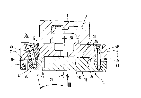
The milling cutter essent;ally cG",p,ises the base body 3, which can be driven in a rotating
manner around its longitudinal axis 1 through the machine tool spindle 2, and support
bodies 4 which are distributed over the surface of the latter and are iolended for cufflng
plates 5 made of a hard cutting material. The support bodies 4 are supported by means of
a stopper in the base body 3 against the centrifugal force operating on them radially to
the longitudinal axis 1. The support used here is the step 6 implemented against the
centrifugal force. The support bodies 4 are tensioned against the base body 3 and
specifically against the step 6. The tensioning is basically made in the direction of the
clamping axis 7.
The end face of the base body 3 is formed through a central area 8 and through aperipheral area 9 surrounding this in a collar-like manner (Fig. 6a). The height of the
peripheral area 9 projects beyond the height of the central area 8 in the direction of the
longitudinal axis 1 against the work piece 10 to be machined. The central area 8 and the
1 83423
WO 95/22425 PCT/EP95/00547
peripheral area 9 form between each other the step 6 which functions as the base body
stopper. The support bodies 4 form at their base 11 a counter-step 12 which cooperates
in an interlocking manner with the step 6 of the base body 3. The support bodies 4 are
tensioned with their counter-step 12 against the end face of the base body 3 in the
direction of the clamping axis 7 such that the counter-step 12 is drawn with its inner insert
13 to the step edge 14 (Fig. 6a) in such a way that the step edge 14 exerts pressure in a
wedge-like manner on the insert 13 of the counter-step 12.
A mounting plate 15 is d;;,posed at the end face of the base body 3, said end face being
formed by the central area 8 and the peripheral area 9. Using the grooves 16 which are
arranged on its circ~"lfarence and are open appr~xi",ately radially outwards themounting plate 15 embraces the support bodies 4 Iying in the grooves 16 at the sides and
the rear in an interlocking manner (Fig. 3). The grooves 16 thereby operate in the manner
of pockets filled with the support bodies 4.
The central area 8 and the peripheral area 9 are level and run parallel to each other. They
are at a right angle 17 to the longitudinal axis 1 of the base body 3.
The step 6 between the central area 8 and the peripheral area 9 contains a stepped
surface 18 (Fig. 6a). It is formed by the surface area of a cylinder. Due to the improved
inte,locki"g bond, i.e. the more efficient shifting security in the direction of the longitudinal
axis 1 the stepped surface- 18 is provided with an undercut which is most easily formed
by the surface area forming - instead of a cylinder - a truncated cone, with thelongitudinal axis 1 of the base body 3 forming the cone axis. The cone forming this
surface area tapers in the direction of the work piece 10, i.e. in the direction of the arrow
19 (Figs. 1 and 6). Due to the fact that the stepped surface 18 has this advantageous
cone surface area it - together with the peripheral area 9 - forms an angle 20 of less
than 90 with the central area 8. The step 6 in the base body 3 runs conce"l,ic to the
longitudinal axis 1. The stepped edge 14 thereby forms a circle 21 around the central
point 22 of the milling cutter (Fig. 3) i.e. around the longitudinal axis 1.
The support bodies 4 are tensioned with their bases 11 against the peripheral area 9 of
the base body 3. The bases 11 of the support bodies 4 are level and lie with surface
contact on the peripheral area 9. The counter-steps 12 of the support bodies 4 are formed
through a mold projection 23 extending beyond the support body base 11. The flanks 24
of the mold projections 23 which flanks lie approximately radially outwards when the
21 83423
WO 95/22425 PCT/EP95/00547
support bodies 4 are in the mounted position have a surface structure that complements
the stepped surface 18 of the base body 3 such that they lie with surface contact on the
stepped surface 18.
The support bodies 4 are each tensioned by one straining screw 25 (Fig. 2) with the base
body 3. The straining screw 25 permeates the base body 3 from the driving side 26 facing
away from the support body 4 and it can also be operated from the driving side 26 of the
base body 3 which p,.,~ctc radially beyond the machine tool spindle 2 in a flange-like
manner. The clamping axes 7 of the straining screws 25 form with the longitudinal axis 1
of the base body an acute angle 27 opening to the driving side 26. The support bodies 4
are thereby tensioned both with their bases 11 as wel~ as with the outer flanks 24 of their
mold projections 23 against their opposile areas 9 18 on the base body 3. The clamping
axes 7 of the straining screws 25 cut the support bodies 4 appr~,~i",~lely in the region of
their central longitudinal plains 28.
The support bodies 4 are positioned on the base body 3 with their central longitudinal
plains 28 divergent from an exact radial position to the longitudinal axis 1 of the base
body 3 such that their flank end 29 on the peripheral side bearing the cutting plate 5,
projects beyond the exact radial pos;tion in the ,o~lional direction 30 (Fig. 3).
The mounting plate 15 protrudes with an annular pr~je~Aiol) 31 which is concentric to the
longitudinal axis 1 of the base body 3, beyond the level of the peripheral area 9 of the
base body 3 in the direction of its central area 8. With its appruAi,,,ately cylindrical
peripheral surface 32, the annular projection 31 fits pe, r~lly in an interlocking manner on
the stepped surface 18 of the base body 3.
The end face 33 of the mounting plate 15 lies approxin,ately on the plane tensioned by
the cover surfaces 34 of the support bodies 4. In a pr~r.ed embodiment the mounting
plate 15 is permeated by penetration channels 35 for co",pressed air (Fig. 9). The
compressed air is blown through the penetration channels 35 from the inside out of the
central region 36 of the base body 3 to the outside in the direction of the construction joint
37 between the work piece 10 and the milling cutter. The ~ .ng direction 38 is thereby
b~sir~lly radially towards the out~ de. The penetration channels 35 flow into the regi~n of
their apertures 39 in the construction joint 37. The blowing direction 38 is towards the
cutting plates 5 i.e. towards the flank ends 29 of the support bodies 4.
. ` 21 a3423
- WO 9S/22425 PCT/EP9S/OOS47
On the peripheral surface 40 of the base body 3 and the same-sized peripheral surface
41 of the mounting plate 15, each support body 4 is associated with a separate chip
space 42, opening outwards (Fig. 5). The chip space 42 extends as far as the end face
33 of the mounting plate 15 and thereby covers at ieast part of the cutting-plate surface
44 containing the cutting edges 43. The chip spaces 42 are arranged in the rotational
direction 30 of the cuffing-plate surface 44.
The mounting plate 15 is tensioned with the front end 45 of its flange-like peripheral
region 46 protruding radially beyond the annular projection 31 against the parallel
peripheral area 9 of the base body 3. The fixing screws 47 are screwed in from the driving
side 26 of the base body 3 into the mounting plate 15. The clamping axes 7 of the
straining screws 25 for the support bodies 4 run at an angle to the longitudinal axis 1 of
the base body 3. The support bodies 4 are tensioned with their clamping flanks 50
opposite the relevant cutting-plate flanks 49 against the counter-flanks 51 of the
associated grooves 16 of the mounting plates 15. The grooves 16 of the mounting plates
15, which grooves embrace the support bodies 4 in an interlocking manner taper radially
outwards in a slightly cone-like manner.
Figs. 9 and 10 show the milling cutter in acco.dance with the invention as a unit with the
surrounding housing of a device for removal or suction of the chips. Cor"pfessed air is
blown b~sir~lly radially outwards via the machine tool spindle 2, or the central region 36
of the base body 3, through the penel.dlion channels 35, out of the apertures 39 into the
w~rkil,g level, or the construction joint 37. Due to the blowing di,~1ion 38, the chips
arising in the region of the cutting plates 5 are forced into the region of the peripheral
surface 40, 41 of the base body 3 and the mounting plate 15, where chip spaces 42 are
arranged on the cutter surface for their reception. From there, the chips are sucked up,
basically radially outwards, in the direction of the arrow 52. A sucking action is already
attained through the centrifugal force arising as a result of the rotating movement of the
cutter head. This centrifugal force is supported and strengthened through the suction
applied in the direction of the arrow 52, or through the compressed air introduced into the
milling cutter in the direction of the arrow 53.
The milling cutter in accordance with the invention is particularly suitable for high rotating
speeds with cor-espondingly high centrifugal forces.
21 83423
- WO 95/22425 PCT/EP95100547
Reference List 37 Constnuction joint
38 Blowing direction
Longitudinal axis 39 Aperture
2 Machinetoolspindle 40 Peripheral surface
3 Basebody 41 Peripheral surface
4 Supportbody 42 Chipspace
5 Cutting plate 43 Cutting edge
6 Step 44 Cutting plate surface
7 Cla""~;ngaxis 45 Frontend
8 Central area 46 Peripheral area
9 Peripheral area 47 Fixing screw
10 Work piece 48 Axis
11 Base 49 Cutting plate flank
12 Counter-step 50 Clampingflank
13 Insert 51 Counter-flank
14 Stepped edge 52 D:.e~on of arrow
15 Mounting plate 53 Direction of arrow
16 Groove
17 Rightangle
18 Steppedsurface
19 Direction of arrow
20 Angle
21 Circle
22 Central point
23 Mold projection
24 Flank
25 Straining screw
26 Driving end
27 Angle
28 Central longitudinal plane
29 Flank end
30 Rotational direction
31 Annular projection
32 Peripheral surface
33 End face
34 Coversurface
35 Penetration channel
36 Central region