Note: Descriptions are shown in the official language in which they were submitted.
wo 95/23689 2 1 8 3 7 8 1 PCT/US95102652
WALL BOARD TAPE HAVING FIBROUS SURFACE
.
Back~round of the Invention
This invention relates to wall board tapes, inclu~in~ dry wall tapes, and
particularly relates to a novel wall board plastic tape having fibrous surface to
which wall board compound can readily be adhered in substantial thickness in a
single coat without fear of the compound cracking or spalling The tape is
specifically applicable to corner joints as well as flat joints and, in one form, is
usable on curved joints, such as curved or arched openings, and on the inside oroutside tangent corner of a two barrel ceiling. The tape has a fibrous surface
coating on both top and bottom sides which attaches to the drywall or wall boardsetting compound and adheres the tape to the underlying wallboard surface.
Present plastic and paper wall board tapes have certain drawbacks.
Water based dry wall or wall board setting compound is difficult to adhere
permanently to plastic tapes because plastic products have a smooth surface and
some plastics can leak out plasticizers over time which tends to break down the
bond between the compound and the tape. To create a mechanical bond, the
tape must be roughened or perforations made in the tape to help the adherence
problem. As the compound is curing, it sags or oozes from the perforations and
drys as a protrusion on the surface. These protrusions make the application of avery thin second coat extremely difficult. These procedures also are costly
and/or time consuming.
A difficulty with paper tape is that it tends to absorb water and soften
when applied over thick amounts of compound as is necessary when taping
irregular joints and corners. When the paper softens it sages and deforms, and astraignt line corner is not achieved. Thus, paper must be applied over thin layers
of compound which requires a number of coats of compound or the
imperfections must be pre-filled, increasing labor costs and time of finishing.
W O 95/23689 2 1 8 3 7 8 1 PCTAUS95/02652
A principal object of the present invention is to provide a plastic tape
which can be adhered by water based # I taping compound in a one coat
application to an inside corner or over a two coat application when applied to an
outside corner to provide a permanent straight corner. This is achieved without
using any mechanical fasteners. When taping an inside corner, dry wall
compound is applied to the wallboard surfaces at the corner, the tape is appliedand wiped smooth with a taping knife to embed the tape into the compound and
remove excess compound, and a finish coat of compound is applied over both
wings of the tape and struck offin a finish coat. The fibers on the tape act to
center the tape and act as shims to keep tape parallel with the wall surface when
the taper bears down on the tape while wiping the tape clean.
Another object is to provide a plastic tape having an embossed raised
center portion with a straight edge to facilitate creasing in a straight line so as to
define a straight corner when applied to a corner joint. Still another object is to
provide a plastic tape with a raised center and depending wings which are coatedon both surfaces with fibers to enhance adherence of water based dry wall
compound to the tape. Another object is to provide a flat joint tape with fiberson the surfaces. A further object is to provide a method of making such tapes.
These and other objects and advantages will become apparent
hereinafter.
Summary of the Invention
The present invention comprises a plastic wall board tape having a
center section bendable in a straight line with depending wings coated on both
surfaces with fibers to create a mechanical bond with water based taping
compound.
The invention.also consists in the parts and in the arrangements and
combinations of parts hereinafter described and claimed.
WO95/23689 2 1 8 3 7 8 1 PCT/US95/026S2
Description of the Drawings
In the accompanying drawings which form part of the specification and
wherein like numbers and letters refer to like parts wherever they occur -
Fig. I is a fragmentary plan view of a section of tape showing theinvention;
Fig. 2 is a sectional view taken along line 2 - 2 of Fig. I;
Fig. 3 is an enlarged t;agmentary sectional view of a part of the tape;
Fig. 4 is a fragmentary sectional view of an inside joint showing one
wing of the tape covered with a finish coat of taping compound and the other
wing merely skim coated on the outer edge;
Fig. 4A is a fragmentary sectional view of an outside joint showing both
tape win;,s with finish coats of taping compound;
Fig. 5 is an enlarged fragmentary sectional view of the installation of
Figs. 4 and 4A whérein the tape wing is finish coated and showing the
engagement of fibers and taping compound;
Fig. 6 is an enlarged fragmentary sectional view of a joint showing
inside and outside corners;
Fig. 7 is a fragmentary sectional view of a flat joint showing the tape
and taping compound applied thereto;
Fig. 8 is a perspective view showing the modified tape of Fig. 10
applied to a curved corner;
Fig. 9 is a fragmentary view of a modified form of tape;
Fig. 10 is a fragmentary plan view of a further modification of the tape
of this invention;
- Fig. I I is a sectional view of a further modification of the tape of this
invention;
W O 95/23689 ~ 1 8 3 7 8 1 PCT~US95/02652
Fig. l 2 is a sectional view of a further modification of the tape of this
invention;
Fig. 13 is a fragmentary perspective view of the tape of Fig. 9 applied
to a barrel ceiling; and
Fig. 14 is a schematic flow diagram of a process for making this
invention.
Detailed Description
The preferred form of the present invention is embodied in Figs. I - 3
and comprises a dry wall tape 10 which normally is sold in 50 - 100 foot rolls.
The tape 10 is made of plastic, preferably polyvinyl chloride (PVC) and includesa raised center segment 11 and outwardly depending side segments 12.
Adhered to the top and bottom of the center segment I I and the side
segments 12 are a plurality of discrete fibers 13 (see Fig. 3). The fibers 13 are
known as floc and can be Nylon, rayon, Dacron, polyester, cotton or other
cellulose, or other similar fibers or combinations of fibers. The preferred fibers
are cotton and nylon and combinations of nylon and cotton. Nylon fibers or
other water impervious fibers are used where a waterproof application is
reguired. This would typically be a bathroom shower stall or tub installation oran exterior application. Typical of such are DURA/ROCK concrete board, or
DRYIT exterior system, etc. The fibers 13 have a diameter of about I - 3 Tow
deniers, but larger or smaller sizes will work. The preferred lengths of fibers 13
are about 0.005 to about 0.030 inches. Longer or shorter fibers will work,
however. Those parameters are preferred because when the coated tape is
applied to a wall joint and only the tape edge is skim coated, the uncoated
surfaces can be painted as a finished wall. The preferred size fibers are small
enough to lay down when painted so the paint will create a smooth finished
surface. Larger sized fibers do not give the desired smooth, painted surface.
WO 95123689 2 1 8 3 7 8 1 PCT/US95/02652
When tlle fibers 13 are cotton, the product is less costly and the water
absorption charactertistics which help the fibers bond to the water base dry wall
compound are better.
Fig. 14 shows schematically a process for making tape. The coated
tape is produced by passing flat plastic tape first through a glue applicator, where
a suitable adhesive is rolled or sprayed over the top and bottom surfaces. The
tape then is passed to a chamber where a predetermined amount of the fibers are
applied. The glue cures and dries and permanently adheres the fibers to the tapeand the excess fibers are then blown and mechanically brushed from the tape.
The flat roll of tape is then passed through a printing die where desired indicia
are applied. The next step is to emboss the center sections on the tape. Finally,
the tape is passed through cutting dies where cut-outs in the wings are made, ifdesired. Application of the fibers creates completely coated upper and lower
surfaces with numerous voids. Thus, when taping compound is applied to the
tape, it is mechanically entrapped in the numerous voids and also attaches to the
outer surfaces of the fibers, thus enhancing the effective surface area of the tape
and creating a powerful bond between the tape and the wallboard.
The amount of fibers on the tape is controlled by the amount of glue or
bonding agent which is applied to the tape as well as by the time the tape is in the
application chamber. The number of fibers also depends on the absorbency of
the fibers and the cost of the fibers. Only enough fibers are required to adherethe taping compound to the tape and the wallboard to eliminate cracking and
spallin;, of the taping compound on drying.
The coating is uniform in appearance and to the naked eye appears to
be a smooth surface. In fact, it can be painted over without skim coating with
taping compound.
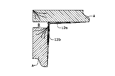
In applying the tape 10 to an inside corner (as shown in Fig. 4), the
taping compound is applied to the wallboard A, the tape 10 is applied, wiped
wo 95/23689 2 1 8 3 7 8 1 PCrlUS95/02652
smooth with a taping knife, and cured. The second (and final) coat requires onlystriking offthe compound to the outer edges ofthe tape 10 as shown in wing
12a. The tape edge produces a straight edge for the installer. The top surface of
the tape can be directly painted over without the installer applying any
compound to it. Of course, compound can be applied to the tape surface if
desired as shown in wing 12b. Fig. 4 shows the tape 10 used to bridge an
opening B between poorly fitted wallboard sections A. The rigidity of the plastic
tape 10 allows this.
Fig 4A shows the tape 10 applied to an outside corner where the
wallboard sections A do not fit snuggly, also resulting in a void B. The tape 10can be used to bridge the opening between the poorly fitted wallboard. The tape
] 0, being plastic has sufficient rigidity to frame the opening B between the
wallboard segments without the opening being filled with taping compound.
Because the taping compound bonds strongly to the fibers 13 on the tape 10, the
tape 10 becomes extremely strong and permanently bonded to the wallboard.
Lines 14 printed on the top surface of the tape segments 12 help the
assembler line up the tape on its initial application. By looking down the jointalong the lines 14, the applicator can tell if the tape 10 is on straight.
The tape 10 has length indicia 15 printed on the edges at regular
intervals (6" or 12") to make installations of desired lengths very quick and easy.
The tape 10 preferably has a longitudinal rolled or embossed line of
weakness 16 along the top of the center segment I I to facilitate bending or
folding the tape 10 at all angles without distortion. However, with a V-shaped
center segment I I, the tape 10 tends to be foldable along the apex of the "V"
without a definite weakening line. The high speed embossing of the "V" fatigues
the plastic at the apex of the "V".
To facilitate using the tape on curved or arched edges, Fig. 9 shows a
modified tape 20 which includes a raised center segment 21 preferably having a
wo 95/23689 ~ ~1 8 ~ Y ~ 1 PCT/USg5/02652
line of weakness 22 down the center thereof. The depending side segments 23
comprise spaced elements 24 which may be aligned as shown or may be offset
and staggered from one side to the other. The elements 24 preferably are
somewhat V-shaped with the large ends of the V-shaped elements 24 being
connected to the center segment 21 and the small ends of the segments 23 being
connected together by a removable tear strip 2S. The tear strips 25 hold the
elements 24 together before installation, but are removed when a curved corner
is taped to allow the elements 24 to move apart or closer together as the tape is
applied around a corner. The elements 23 can be rectangular or other suitable
shape which allows the elements 23 to move together or apart as the tape 20 is
bent during application.
Use of the tape 20 is shown in Fig. 13 as applied to a barrel ceiling.
Only the part of the tear strips 25 are removed where the tape 20 is applied to a
curved surface. The tear strips 25 remain on the straight edges to rigidify the
tape and provide a straigllt edge for finishing.
Fig. 10 shows a further modification of the tape 30 for applying along
an arch wherein only one side 31 of the tape 30 has to expand or contract and
the other side 32 lies smoothly on the tope ofthe wall arch segment. This is
shown in Fig. 8. In this variation, the first taping wing 31 has spaced segments33 contented by a removable strap 34. The second wing 32 is solid and
constructed to lie smoothly on the flat side of an arch segment.
Fig. I l shows another embodiment of the tape 40 which has three
offset elements 41,42,43 hl the center connecting the wings 44. Both surfaces ofthe tape 40 are coated with fibers 13 The tape 40 is similar to the tape shown in
my Patent No. 5,037,686 and has the same advantages. It also can be formed
with the slots and connecting tabs shown in Figs. 9 - 10.
Fig. 12 shows another variation of the invention embodied in a flat tape
50 which is coated with fibers on both sides. The tape 50 is suitable for flat
WO 95/23689 PCT/US95/02652
2 1 8378 1 8
joints and can have a centerline embossed therein for folding to make a straightedge for corners.
The tape 10,20,30,40,50 itself preferably is PVC although other semi-
rigid polymeric materials are satisfactory.
The tape 10 is about O.OIS - 0.020 inches (preferably about 0.017
inches) in thickness to provide sufficient rigidity to bridge gaps in wallboard
installation while having enough flexibility to be packaged in rolls without taking
a set. It also is thin enough to minimize the weight of the tape and the amount of
dry wall compound needed to apply it.
Thus, among the advantages that the tape of this invention has over
known dry wall tapes are the following:
I ) Being plastic the tape can be applied to situations where the wall
board joint has deep imperfections and thick coatings of wall board compound
may be required. The plastic substrate prolongs drying time of the compound
and the compound does not shrink as it dries because it dries from the inside out
due to the plastic tape retaining moisture and encapsulating the compound
against the wallboard.
2) Because of the rigidity of the tape, large imperfections in wall
applications can be overcome by filling the imperfections with compound,
applying the tape, aligning the corners using the printed indicia, and allowing the
compound to dry without the tape shrinking, bulging or moving. The initial
bonding of the fibers holds large amounts of compound in place until cured.
3) Because the tape is not softened by large amounts of wet compound
as would be the case with a paper tape, the first coat stays straight and uniform
as it cures. This eliminates the need to pre-fill large imperfections in layers to
make a smooth installation surface.
4) In inside corner applications, the tape is applied to a bed of
compound, wiped down with a taping knife so that only the edges of the tape
wo 95123689 2 1 8 3 7 8 ~ PCT/USg5/02652
require a finish coat. The surface in an inside corner is a suitable finish surface,
ready for painting or a textured surface. A finish compound coating can be
applied, if desired. Thus, in an inside corner the installer only has to strike the
outside edge of the tape, using the edge as a straight edge guide, to co"")lete
application. The top surface of the tape can be painted or skim coated with
compound.
5) Since no finish coating of compound is required on inside corners,
no cracks will ever form at the joint because cracks tend to form in time in taped
joints because of settling, shrinkage~ etc.
6) Since the tape has printed alignment and length indicia, inct~ tion
of desired lengths is quick and easy and corners can be installed quickly and the
tape can be lined up to define a straight corner or edge.
7) When the tape is used on an outside corner, the embossed center
edge is used as a straight edge for striking offthe compound in a straight line.8) The angled sides and/or line of weakness caused by embossing the
center segment of the tape allows it to be folded without bulging the sides and
allows a quick straight fold.
9) Since the tape is plastic, it is waterproof and can be used on
waterproof board in wet areas without rusting. Also, small cracks in the cornersof tub and shower stalls will not leak when this tape is used.
10) The removable tear strip used with the raised center segment
allows rapid installation on curved corner joints. If it is left on for straight areas,
it gives rigidity to the tape and a straight continuous edge in these areas, with a
smooth transitition to the curved areas where the tear strip is removed.
I I ) The taper can bear down on the tape without squeezing all of the
compound out from beneath the tape because the fibers adhere the compound to
the tape and act as a shim or spacer to hold some compound between tape and
wallboard. On any corner, the tape centers itself on the corner and aligns the
wo 95/23689 PCT/US95/02652
21837~1 10
wings parallel with the wall surfaces to position the raised or center of the tape
to coincide with the line defined by the intersection of the wall surfaces.
12) The taper can align the tape in a straight line by bearing down on
each leg so the tape in effect is self-centering on the corner.
13) If necessary because of irregular sub-framing, the tape also can be
aligned by hand using the prepositioned lines on the tape, because the taping
compound sets more slowly with the plastic tape prolonging curing time.
The preferred plastic substrate is polyvinyl chloride, but other plastics
can be used. A specifically preferred product is ARLINYL 940 by Arlington
Mills, Inc. of Arlington Heights, Illinois. The product has the following
properties and other materials should have similar characteristics.
GENERAL PURPOSE COPOLYMER
POLYVINYL CHLORIDE (PVC) DESIGNATED "ARLINYL" 940
PROPERTY VALUE
SPECIFIC GRAVITY 1.38-1.42
WATER ABSORPTION .28
TENSILE STRENGTH 5000 PSI,PLUS
ELONGATION 150%, PLUS
MODULUS OFELASTICITY 310,000-350,000
IN TENSION
FLEXURAL STRENGTH 10,000-12,000
MODULUS OF ELASTICITY 380,000-420,000
IN FLEXURE
IZOD IMPACT STRENGH HIGH
FLAMMABILITY SELF-EXT.
W O 95/23689 2 1 ~ 3 7 8 1 PCTrUS95/02652
-- 11
~AT DISTORTION 62-64
(264/LB./IN. FIBER STRESS
HARDNESS (SHORE D) 72-78
VICAT SOFTENING POINT 84 (+3)
Thus it is seen that the present invention achieves all of the objects and
advantages sought therefor and this invention is intended to cover all changes
and modifications of the example of the invention herein chosen for purposes of
the disclosure which do not constitute departures from the spirit and scope of the
invention.