Note: Descriptions are shown in the official language in which they were submitted.
- CA 02183854 1996-08-21
WO 96!00331 PCT/US95l0580?
218~85~
INTERLOCKING MORTARLESS BUILDING BLOCK SYSTEM
BACKGROUND OF THE INVENTION
This invention relates in general to blocks for use
in construction of walls, buildings and the like and,
more specifically, to a mortarless building block system
generally requiring only two different block
configurations.
Conventional concrete block construction uses
rectangular blocks, generally having one or more cavities
through the blocks from top to bottom. A layer of mortar
is thrilled onto a foundation and a course of closely
spaced blocks are laid on the layer, with additional
mortar applied between the contiguous block ends.
Another layer of mortar is applied to the top of the
first course and additional courses are similarly laid,
generally staggering the block ends from course to
course. Great care and skill is required to achieve
level courses and a truly vertical wall. Because of the
time and skill required for such construction, costs are
high.
Various types of interlocking blocks have been
devised in the past to facilitate the construction of
block walls and other structures. Most such blocks have
been very expensive to produce since the interlocking
portions, usually grooves or protrusions, are normally
cut into the blocks after they have been formed by
molding. Further, it is difficult to maintain the
required tight tolerances required for accurate
construction of large walls or other structures through
the molding and cutting steps . The prior blocks often
required additional finishing or grinding steps to meet
the require tolerances.
Excellent interlocking mortarless building blocks
overcoming many of these deficiencies are describe in
CA 02183854 1996-08-21
WO 96100331 ~ PCT/US95I05807
G
U.S. Patent No. 3,888,060, and 4,640,071, both granted to
the inventor of the present invention. Those blocks have
been used successfully for many years. These blocks are
assembled in courses, with the block joints staggered and
continuous vertical open cells into which reinforcing
bars ("rebar"j and wet concrete can be inserted. While
highly effective, these blocks require that rebar be
inserted in lower courses, with blocks in later courses
lifted over the ends of ~he rebar as the structure
advances and wet concrete is periodically poured into the
cells containing the rebar. Thus installing blocks over
rebar can be a significant. problem with tall structures.
Also, three or more different block configurations
may be required for many structures, such as walls,
buildings with openings and floor panels connected to the
block wall. Additional block configurations require the
manufacture of addit:i.onal expensive molds and increased
cost and time in changing mo~.ds in a block making machine
and maintaining and inventory of the different block
configurations.
Therefore, there is a continuing need for
improvements in these successful mortarless block systems
to permit lower cost block manufacture and lower cost and
more rapid structure assembly from the blocks.
Additional benefits will derive from more attractive
blocks, especially at structure corners, and the ability
to incorporate different block face and/or structure
designs, interconnected floor panels, etc while
minimizing the number of different block configurations.
SUI~1ARY OF THE INVENTION
The above noted problems are overcome, and advantages
achieved, by a block system which includes two basic
block configurations .including a first elongated block,
typically having a lengtru at least twice the block
CA 02183854 1996-08-21
WO 96100331 PCT/US95105807
21~~85~
3
height, and a second, short block, typically no more than
half the length of the long block, for filling in at wall
ends and openings , etc . , where long blocks are laid in
staggered courses.
Each of said first, long, blocks has a pair of
spaced, upright sidewalls each having flat top and bottom
surfaces and generally parallel outermost side surfaces.
The block face surfaces may have various decorative
designs, as desired. Block end interlock means,
typically cooperating vertically oriented tongue-and-
groove arrangements, are provided at the ends of the
sidewalls. A first transverse wall extends between the
sidewalls at a first end of the block. A second
transverse wall extends between the sidewalls at a
selected location spaced from the second end of the
block. If desired, additional transverse walls could be
provided for added strength in locations that do not
interfere with the interlocking means.
At least three protrusions along the inner side of
the sidewalls, each having a base generally coplanar with
the bottom surface of the sidewall and a tip extending
above the upper surface of the block, a.re provided. The
first and second protrusions are located adjacent to the
second end of the block (which may also form part of the
second transverse wall ) and a third protrusion is located
adjacent to the first end wall. The tips of the
protrusions extending above the top surfaces of the
sidewalk are sized and located to interlock with the
next higher course which is laid in a staggered
relationship to the lower course.
Between-course interlock means are provided on the
sidewall opposite the third protrusion and on the first
transverse end wall to interlock with a second (short)
block in the next higher course, with the short block is
laid parallel to the other blocks in that course.
The second, short, blocks have sidewalls generally
similar to the long block sidewalk and two transverse
CA 02183854 1996-08-21
WO 96/00331 ~ PCTlUS95105807
4
end walls. Two protrusions are provided on the interior
of the sidewal.l~, extending from a base generally
coplanar with the bottom surface to a tip extending above
the upper surface caf the sidewalk . The upwardly
extending tips interlock with the between-course
interlock means on the long blocks. The short blocks may
also be laid up to form a column, with each succeeding
short block oriented 180° to the next lower and next
higher block.
When the embodiment of the long block described
above is used in building a wall in which long rebar
extends up from a ~:oundation, each block at the rebar
location is lifted over the rebar and lowered into
position with the rebar extending up through the opening
bounded by sidewalk and transverse walls. Then wet
concrete is poured :i.nto the opening to bond to the blocks
and rebar.
If desired the second transverse wall may be
substantially aligned with the two opposite protrusions
or may be spaced further from the second end than those
protrusions, in effect leaving a deep open. end,
preferably at least l,/4 of the block length.
In the block embodiment having the second transverse
wall at least 1/4 of the block length from the open end
are used to build a wall on a foundation having
vertically extending long rebar secured in the
foundation, the b.!_ocks may be placed with the rebar
opening between the second transverse wall and the
second, open, block end, so that blocks can be placed
from either side of the rebar to form a vertical opening
without having to Tuft blocks over the rebar.
In some structures, such as walls or building
enclosures, it is desired to have concrete floor panels
extend horizont.al..ly from the block wall at selected
heights. The floor. panels should extend into the wall
about half the wall. width and be supported by the wall.
With prior blocks, attempts to split blocks vertical
CA 02183854 1996-08-21
WO 96/00331 PCTlUS95/05807
218~85~
along their longitudinal centerline to form shell blocks
and place them next to the floor panel- prior to laying
the next course above the floor panel was often
unsuccessful, since nothing held the shell blocks in
place and they tended to fall away. With the blocks
described above, the blocks can be cut along the
longitudinal vertical centerline forming two shell blocks
each of which can and placed next to the floor panel and
be held in place by the interlocking protrusions
described above while the next course is laid. If
desired, shell blocks may also be produced by placing a
longitudinal separator in the mold prior to block
formation so that two shell blocks result.
In some cases, horizontal rebar extending through
some block courses is required by building codes . The
blocks of this invention may be easily molded with
notches in the upper edges of the first transverse end
wall and the second transverse wall to allow the
horizontal rebar to be installed and held in place by wet
concrete placed in the cavities within the blocks. Or,
notches extending slightly down an end wall may be
provided so that the upper edge of the' end wall may be
broken away to provide room for horizontal rebar.
BRIEF DESCRIPTION OF THE DRAWING
Details of the invention, and of preferred
embodiments thereof, will be further understood upon
reference to the drawing, wherein:
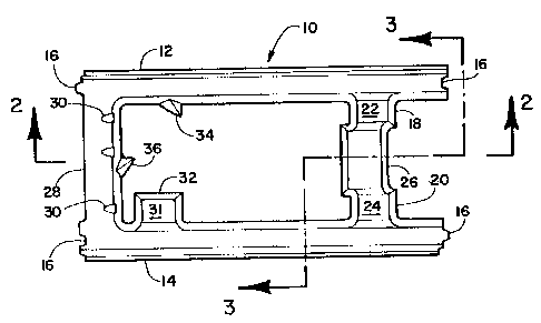
Figure 1 is a plan view of a first, long, block of
this invention;
Figure 2 is a section view taken on line 2--2 in
Figure 1;
Figure 3 is a section view taken on line 3--3 in
Figure 1;
Figure 4 is a plan view o.f a second, short, block
according to this invention;
Figure 5 is plan view of a long block placed over
CA 02183854 1996-08-21
~~~~~ 95/ ~~5807
,._. ~ . - - _
a ~ :~,t°tlt i.,y t~
and aligned with a short block arranged parallel to the
long block to form the end of a wall;
Figure 6 is a plan view showing the interlocks in a
wall formed by one long block overlapping two long
blocks;
Figure '7 is a plan view showing a column formed by
two overlapping short blocks arranged at 90° to each
other;
Figure 8 is a plan view showing the interlocks at a
corner formed by two overlapping long blocks;
Figure 9 is a perspective view of an embodiment of
the long block having an extended open end;
Figure 10 is a vertical section through a wall
constructed of the blocks of the embodiment shown in
Figure 9; and
Figure 11 is a perspective view of a wall having a
connected floor panel.
DETAILED DESCRIPTION OF PREFERRED EI~ODIMENTS
Referring to Figures 1-3, there is seen an elongated
first block 10 having a pair of spaced, upright sidewalls
(face shells? 12 and 14. Sidewalls 12 and 14 have
generally parallel outer surfaces , although a slight
taper from narrow at the top to wider at the bottom is
desirable for ease of removal from the mold in which the
block is formed. If desired, a greater taper could be
used to provide shadow lines at the course interfaces.
Any suitable finish, color and texture may be used.
Sidewalls 12 and 14 have flat top and bottom surfaces.
For ease of removal, eliminating the need for complex
molds, the block should have no undercuts..
Block interlock means 16 are provided at each end of
each sidewall to lock adjacent blocks together.
Preferably, the block interlock comprises a vertical
tongue and groove arrangement as shown.
First and second opposed protrusions 18 and 20 are
provided near a first end of block 10. Protrusions 18
and 20 lie along the inner surfaces of sidewalk 12 and
14, extending from a base that is substantially coplanar
~~~~i~ - _.
CA 02183854 1996-08-21
WO 96/00331 PGTIUS95/05807
X183854
with the bottom surface of the block to tips 22 and 24
extending just above the top surface. When staggered
courses of these blocks are assembled, the protruding
extended tips 22 and 24 extend into the upper course,
engaging the bases of the upper block protrusions to hold
the blocks in place (this interlocking being best seen in
Figures 6-9). Protrusions 18 and 20 are tapered,
narrowing from bottom to top to allow easy removal from
the mold and to position the top and bottom ends for
proper interlock for the selected overall block
dimensions.
A first transverse wall 26 extends between sidewalls
12 and 14 near the first end of block L0. In the
embodiment shown in Figures 1-3, transverse wall 26
extends between protrusions 22 and 24. Preferably,
transverse wall 26 is lower than the sidewall, to provide
room to run horizontal rebar therethrough, if desired.
A second transverse webb 28 extends between
sidewalls 12 and 14 at the second end of block 10. If
desired, a plurality of notches :30 may be provided in
transverse webb 28 to aid in breaking away an upper
portion of that wall to permit rebar or the like to
extend horizontally through the block. Alternatively, the
top edge of webb 28 could be molded at a lower height to
permit passage of rebar or the :Like. '.Che lower portion
of the top edge of webb 28 may be formed by breaking away
portions of the top wall or by molding webb 28 with one
or more depressions therein.
A third protrusion 32, which is provided along one
sidewall adjacent to the second transverse webb 28, is
generally similar to first and second protrusions 18 and
20 and is positioned to interlock with protrusions on
staggered blocks in the next succeeding course, as
discussed above.
First and second tapered between--course interlock
means 34 and 36 are provided on the interior of sidewall
12 and second transverse end webb 28. Each has
CA 02183854 1996-08-21
8
PCTIUS 95/ 05807
IPEA/US 3 0 SEP 1996
approximately a right triangular cross section, which
could be curved and approximate a right triangular cross
section so long as the one surface is substantially
perpendicular to the sidewall surface, as shown.
Alternatively, the face of interlock means 34 could lie
at an angle greater than 90'' to the wall where the
corresponding tip has a substantially identical angle.
Interlock means 34 tapers from the bottom surface of the
block to an intermediate height. These means are
configured and positioned to cooperate with tips of
protrusions on the next lower course, as illustrated in
Figures 6-8 and described below. I:n certa:in cases, such
as lintels over a window or other opening,. short blocks
could be oriented perpendicular to long blocks in the
next course, if desired.
Figure 4 shows short block 38 in plan view. Except
for the lesser length, short block 38 is generally
configured as is long black 10, with vertical surfaces
tapered to allow easy removal from the mold. Tongue-and-
groove interlocks 16 match those on long block 10. End
walls may have notches 30 to permit portions of the upper
end walls to be broken away to permit access for running
horizontal rebar or the like.
Protrusions 40 and 42, generally similar to
protrusions 22, 24 and 32 on long block 10, are arranged
on the interior of sidewalk 44 and 46, respectively.
Protrusions 40 and 42 have tips 41 and 43, respectively,
extending above the upper surface of the block 38.
Inwardly directed corners 50 and 48 are preferably
provided to aid in interlocking with protrusion tips on
the next lower course of blocks. The space between
corner 50 and protrusion 40 and between corner 48 and
protrusion 42 is sized to fit t:he tip 31 of the
protrusion 32 in the next lower course of .Long blocks 10
at a wall end or at an opening.
In a structure having a corner between two walls
formed of the long blocks, the tongue and groove means 16
AMENDED SHE~=~
CA 02183854 1996-08-21
PCT/US 95/ 0580?
lPEA/US ~ 0 S E P 1996
at the exposed end of an end block will be exposed,
adding a decorative feature, alternating between surfaces
in alternate courses. At the end of a wall, short blocks
38 will be the last block in every other course. In
order to form the same decorative feature between
succeeding courses, short blocks may be oriented parallel
to the long blocks, with all exposed tongue and grooves
patterns at the end of the wall.
Figure 5 is a detail plan view, showing a long block
above a short block 38, with the two blocks arranged
parallel. For clarity of illustration, references of
block components for the upper course will be identified
as a prime, i.e., the upper block is block 10' while the
lower block is block 38.
Tongues and grooves 16 on both blocks will be
exposed at the end of the assembly. The upstanding tip
43 of short block protrusion 42 will extend upwardly into
the lower surface of long block 10, abutting the base of
long block protrusion 32'. The upstanding tip 41 of
short block protrusion 40 will extend upwardly into the
lower surface of long block 10, abutting the side of
interlock means 34'. Similarly, though not shown, the
upstanding tip 31 of long block protrusion 32' will
extend upwardly into the lower surface of the next short
block 38 above long block 12 when that short block is
laid in place, abutting the base of short block
protrusion 42 and corner 48, as seen in Figure 4. Thus,
these blocks will be firmly held in position.
Figure 6 shows a small portion of a wall with one
block 10' overlapping two blocks 10 in the next lower
course. Again, for clarity of illustration, references of
block components for the upper course will be identified
as a prime, i.e., the upper block is block 10' while the
two lower blocks are blocks 10.
Blocks 10 are abutting, with tongue-and-groove means
16 (not seen) interlocking. Tip 31 of left block 10
extends into the lower surface of block 10° and engages
CA 02183854 1996-08-21
WO 96/00331 PGTIUS95I05807
~1$~~:~
interlock means 34'. Tips 22 and 24 of right lower block
10 also extend into the lower surface of block 10'. Tip
22 engages the base of protrusion 24' and tip 24 engages
the base of protrusion 22'. Thus, the combination of
these interlocks serve to prevent movement of left and
right blocks 10 away from each other i.n any horizontal
direction.
Columns can be formed from short blocks 38 simply by
rotating each succeeding block 180°. The interlocking of
such blocks is shown in Figure 7. As before, components
of the upper block are identified with a prime.
Tip 41 of lower block 38 extends upwardly into the
lower plane of block 38', engaging corner 48 and the base
of protrusion 42'. Tip 43 extends upwardly into
engagement with corner 50 and the base of protrusion 41'.
Thus, relative movement between the blocks in a
horizontal plane is prevented.
Figure 8 shows a portion of a corner formed by one
long block 10' overlapping a block L0 with the two blocks
lying perpendicular to each other. The upwardly
extending tip 22 of protrusion 18 of the: lower long block
10 will interlock with interlock means 36'. If lower
block 10 were reversed (rotated '' in a horizontal plane)
tip 31 of protrusion 32 would extend up into block 10'
and engage interlock means 36'.
While in general long blocks having lengths equal to
twice their widths (e. g., the standard 8 by 16 inch
blocks ) with short blocks having equal widths and lengths
(e. g., 8 by 8 inch blocks) are preferred, other
dimensions may be used, if desired, so long as the long
blocks have lengths at least twice their width and the
short blocks are up to half the length of the long
blocks. For example, a combination of 8 by 24 inch long
blocks and 8 by 8 inch short blocks would be suitable.
With the blocks shown in Figures 1-6, if the blocks
are to be assembled on a foundation with rebar extending
upwardly from the foundation, it is necessary to lift the
~
CA 02183854 2005-08-22
11
blocks over the top of the rebar, so that the rebar
extends upwardly through the overlapping cavities in each
course of blocks. Where the rebar is very long,. the
alternative embodiment of long blocks 51 shown in Figures
9 and 10 may be preferred.
Long block 51 has sidewalls 52 and 54, end wall 56
and three protrusions 58, 60 and 62, interlock means 64
and tongue and groove interconnect means 66, generally
similar to the corresponding features in block 10
described above. In this embodiment, however, second
transverse wall 68 does not extend between protrusions 58
and 60; rather, it is positioned further from the open
block end. The edge of wall 68 closest to the open block
end should be a distance from the open block end equal to
at least about 1/4 of the block length where the block
width to length ratio is about 1:2. With blocks that are
longer relative to the width, or the course-to-course
overlap is not one half of the blocks in succeeding
courses, transverse wall 68 is spaced from the open end
a sufficient distance to provide the necessary open
vertical channel through the wall to accommodate rebar 70
as seen in Figure 10.
As seen in Figure 10, a longitudinal section through
approximately the center of a wall made up of blocks 51,
The blocks in succeeding courses can be moved
horizontally into position with the open ends of the
blocks surrounding rebar 70. In the embodiment shown in
Figure 10, the ends of the blocks in each course fall
half way along the blocks in the adjacent courses. As
can be seen, with .the side of each transverse wall 68
about one quarter of the block length from the block open
end, there is just sufficient space for rebar 70 to run
vertically through the assembled blocks. Greater rebar
space could be provided by positioning the side of
transverse wall 68 slightly further from the open end of
the block. The cavities in the blocks 51 through which
the rebar 70 runs can be filled with wet concrete 72 for
CA 02183854 2005-08-22
12
the desired strengthening.
Figure 11 illustrates how effectively the mortarless
interlocking block assembly of this invention can
accommodate the need to support floor panels 76 at
selected heights along the wall.
The wall 78 is assembled using blocks 10, 38 and/or
70, as desired, to the height at which the floor 76 is to
be installed. Floor panels are emplaced (or cast in
place) with the floor panel edges extending approximately
half way over the wall blocks . Rebar 80 may be installed
in grooves 82 in floor panels and bent to extend up
within the succeeding block courses. Long blocks 10 or
51 (whichever is being used) are cut along a longitudinal
vertical centerline. A course of the resulting half-
blocks 84 is laid adjacent to floor panels 76. Where
practical, the floor panels 76 can be post tensioned
prior to installation of single shell blocks 84, since
this system allows room for the post tensioning tools
after panels 76 are placed on the lower course of full
blocks.
A course of blocks is then laid, with the
protrusions 24 and 32 (not seen) of single shell blocks
84 interlocking with the next succeeding course, holding
the single shell blocks firmly in place. The single
shell blocks are also held in place by the tongue and
grooves 86 at the ends of the sidewalls.
Thus, assembly of the wall can rapidly proceed
without any particular precautions to hold the single
shell blocks in place during assembly, as would be
necessary with prior such half-blocks.
While certain preferred materials, dimensions and
arrangements have been described in detail in conjunction
with the above description of preferred embodiments,
those can be varied, where suitable, with similar
results. Other applications, variations and
ramifications of this invention will occur to those
skilled in the art upon reading this disclosure. Those
CA 02183854 1996-08-21
WO 96/00331 PGT1US95/05807
13
are intended to be included within the scope of this
invention as defined in the appended claims.
I .CLAIM: