Language selection

Search

Patent 2184326 Summary

Third-party information liability

Some of the information on this Web page has been provided by external sources. The Government of Canada is not responsible for the accuracy, reliability or currency of the information supplied by external sources. Users wishing to rely upon this information should consult directly with the source of the information. Content provided by external sources is not subject to official languages, privacy and accessibility requirements.

Claims and Abstract availability

Any discrepancies in the text and image of the Claims and Abstract are due to differing posting times. Text of the Claims and Abstract are posted:

  • At the time the application is open to public inspection;
  • At the time of issue of the patent (grant).
(12) Patent Application: (11) CA 2184326
(54) English Title: SURGICAL INSTRUMENT FOR SUTURING
(54) French Title: INSTRUMENT CHIRURGICAL POUR SUTURES
Status: Deemed Abandoned and Beyond the Period of Reinstatement - Pending Response to Notice of Disregarded Communication
Bibliographic Data
(51) International Patent Classification (IPC):
  • A61B 17/04 (2006.01)
(72) Inventors :
  • HOEL, STEVEN B. (United States of America)
(73) Owners :
  • STEVEN B. HOEL
(71) Applicants :
  • STEVEN B. HOEL (United States of America)
(74) Agent: RICHES, MCKENZIE & HERBERT LLP
(74) Associate agent:
(45) Issued:
(22) Filed Date: 1996-08-28
(41) Open to Public Inspection: 1998-03-01
Availability of licence: N/A
Dedicated to the Public: N/A
(25) Language of filing: English

Patent Cooperation Treaty (PCT): No

(30) Application Priority Data: None

Abstracts

English Abstract


A surgical device is used for manipulating suture needles. The device is formed of
two elongate members hinged together. On one side of the hinge, the elongate members form
a pair of jaws which are relatively moveable. One the other end of the elongate members
there are handles formed which allow the user to manipulate the jaws about the hinge. An
arcuate shield is integral with one of the jaws at its center. The shield extends laterally and
arcuately from the jaw and covers the opposing jaw. The placement of the shield is such
that a needle which is held between the jaws is protected from sticking any one or anything.
The jaw members may be made up of several units forming segmented jaws.


French Abstract

L'invention porte sur un dispositif chirurgical utilisé pour manipuler les aiguilles à suture. Le dispositif comporte deux éléments allongés articulés l'un à l'autre par une charnière. D'un côté de la charnière, les éléments allongés forment une mâchoire relativement mobile. Le dispositif comprend, à l'autre extrémité des éléments allongés, des anneaux qui permettent à l'utilisateur de manipuler la mâchoire près de la charnière. Un écran arqué est solidaire du centre d'un des éléments de la mâchoire. Il se prolonge latéralement et de façon arquée à partir d'un élément de la mâchoire et recouvre l'élément opposé. L'emplacement de l'écran est prévu pour qu'une aiguille tenue dans la mâchoire ne puisse piquer ni rien ni personne. Les éléments de la mâchoire peuvent comporter plusieurs unités formant une mâchoire segmentée.

Claims

Note: Claims are shown in the official language in which they were submitted.

- 6 -
We claim:
1. In a clamp device of the type used for driving,
manipulating, clearing and extracting a suture needle in
surgical procedures that comprises a pair of elongated
members pivotally hinged to each other at a point along
their lengths between their midpoints and their first ends
to form a pair of jaw sections extending from about said
hinge point to said first end and to form a pair of handle
sections from about the hinge point to the second ends of
said members, said jaw sections being adapted to clamp and
hold therebetween a suture needle near its midsection with
the ends of said needle extending laterally from between
said jaw sections, the improvement comprising: a shield
plate affixed to one of said jaw sections over essentially
the full length of said one jaw section and extending
laterally outward and arcuately over the other of said jaw
sections so as to shield from accidental contact with other
objects one end of a suture needle clamped between said jaw
sections near the midsection of said suture needle for
manipulation of said needle by a user of said clamp device.
2. The clamp device improvement as defined in claim
1 wherein said shield plate is an integral part of said one
jaw section.
3. The clamp device improvement as defined in claim
1 wherein said shield plate comprises a plurality of flat
planer sections joined at their longitudinal edges.
4. The clamp device improvement as defined in claim
2 wherein the inner surface of said shield member extends
from the inner surface of said one jaw section that faces
said other jaw section.
5. The clamp device improvement as defined in claim

- 7 -
2 wherein the outer surface of said shield plate extends
from the outer surface of said one jaw section that faces
away from said other jaw section.

Description

Note: Descriptions are shown in the official language in which they were submitted.


' ~ . 2~4326
8~RGIcAL 1,~ FOR SUTURING
BA~K~uN~ OF INVENTION
This invention relates to surgical in~Lrl Ls,
more particularly to a surgical instrument for use in
surgical suturing.
In certain surgical procedures the physician or
surgeon must suture two sides of tissue together. This is
accomplished by passing the point of a needle, often a
curved needle, through the two sides of tissue successively
or simultaneously and then pulling the r~~ ; n~r of the
needle body through the tissue to carry the suture thread
with it. The needle may be pulled or driven completely
through by hand or using in~LL, -ntS such as needle
drivers, haemostats or similar plier-like devices. Whether
the needle is cleared by hand or by in~ LL I L~ there will
be an exposed needle point being moved around a confined
space, usually with numerous nurses' or surgeons' hands,
fingers, wrists or other parts in close proximity. There
is obviously considerable opportunity for accidental
needle-prick of those hands, fingers or wrists, a prick
that in recent years is potentially lethal to those
receiving the wound no matter how minor.
It is an object of the present invention to
provide a surgical in~LL, ~nt adapted for driving,
r-n;p~ ting and extracting or clearing a suture needle
with means protecting against accidental pricks by the
needle point of persons who must have their fingers or
hands near the suturing site during surgical procedures.
SUMMARY OF INVENTION
The present invention provides a needle-driving
instrument having a front integral shield to prevent

~ . 2184326
-- 2 --
accidental needle pricks of personal conducting or
assisting in surgical procedures.
According to the principles of the invention,
there is provided a plier-like instrument with a pair of
elongated members pivotally hinged to each other at a point
between their midpoints and one of their ends to provide
relatively long handles and relatively short "jaws" or
clamp ends. The "jaw" or clamp end of one of the members
is provided with a curved shield plate positioned to guard
the point of the needle held properly between the jaw
members.
BRIEF DESCRIPTION OF THE DRAWINGS
The present invention can be more readily
understood from the following ~PtA; l~d description when
read in conjunction with the ~c~ ,-nying drawings wherein:
Figure 1 is a perspective view of a typical
needle-driver of the prior art;
Figure 2 is a perspective view of a needle-
driver/retriever of the present invention showing the
needle-shield element;
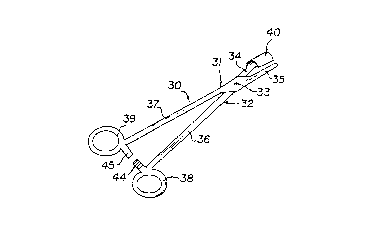
Figure 3 is an elevation view of the needle-
driver/retriever of the present invention in the open
position;
Figure 4 is a front elevation view of the needle-
driver/retriever of the present invention illustrating the
manner in which a curved suture needle is gripped by the
needle and used;
Figure 5 is a front elevation view of the needle-

2 1 84326
driver/retriever of the present invention of a slightlymodified form to better acs~ te the gripping and
chiPl~;nq of a straight suture needle as shown; and
Figure 6 is a front elevation view, partially cut
away, of the needle-driver/retriever of the present
invention having a slightly modified structure.
DETAILED DESCRIPTION OF T~E INVENTION
When referring to the drawings hereinafter, like
elements and features of the invention are designated by
the same reference numbers or same identifications
throughout the various figures.
With reference now to Figure l there is shown in
a perspective view a typical form of a metal surgical clamp
designated generally as 10 of a type often used in the
prior art as a needle-driver/retriever in surgical
oceduLes. The clamp 10 i6 comprised of a pair of
elongated members, ll and 12, pivotally hinged at 13 to
form jaw elements or sections 14 and 15, handle elements or
sections 16 and 17 with grip loops 18 and 19 for better
controlled manipulation. also provided near the loops are
small ratchet tabs, 20 and 21, forming a releasable
pLeS~L~ sustaining lock r ~h~n;~m for holding the jaws
clamped on an object between them.
The needle-driver/retriever of the present
invention, in its preferred : ~:';r ~, is shown in figures
2-5 and is similar in its handle area to the prior art
clamp of Figure 1 thus providing a certain familiarity of
"feel" and operation to the user.
As shown, the needle-driver/retriever of the
present invention designated generally as 30 comprises a

~ ~ 8432~
pair of relatively thin, elongated members 31 and 32
pivotally hinged together preferably closer to one end than
to the other. The shorter portions of the two pivoted
members form a pair of "jaws," 34 and 35. The jaws may be
shaped with generally flattened inwardly facing (opposing)
surfaces to provide clamping action. The larger ends of
the pivoted members form handle members, 36 and 37, and in
the preferred ~ L terminate in grip loops, 38 and
39. As in the prior art, the needle-driver/retriever is
provided with ratchet tabs, 40 and 41, as releasable clamp
hold r -~hAn i ~c . Thus the handle ends of the needle-
driver/retriever of the present invention will have a
familiar "feel" to users who are experienced with Figure 1
type prior art clamps.
Added to and integral with one of the jaw
elements, 34, of the driver/retriever 30, is a shield
element, 40, which is the preferred r-~o~;r-nt is in the
form of a small curved plate that extends longitn~;nAlly
for most of the length of the jaw portion, 34. The shield
element 40 extends laterally from the jaw element on which
it is mounted or of which it is a part curving over the
opposite jaw as shown so that anything held between the
driver jaws is protected from accidental or unintentional
contact with other objects.
The driver 30 may be made of plastic or metal
material such as that used in prior art clamps but
preferably is of a stA;nlP~q steel to provide desirable
overall strength, a springy resiliency in the handles and
a high resistance to breakage. The member 31 and 32 may be
of generally round, oval or rectangular (with rounded edge)
cross-section over most of their length with an appropriate
shape about the pivot point to form the hinge as is well
known in the art. The shield 40 is to be of an appropriate
th;~knpss to be relatively stiff and resistant to bending.

2 1 84326
As may be seen in the end view of Figure 4, the
shield 40 may be made as an extension of the inner-clamp
face 41 of jaw element 34 and be formed in a sufficiently
wide arc to clear, yet shield, a curved suture needle, 42,
clamped between the jaws 34 and 35 as it would be at times
during use.
When used in conjunction with a straight suture
needle such as needle 42a in Figure 5 it may be preferable
to construct the shield 40a as an extension of the outer-
face or surface 43 of jaw 37a as shown. In such a
construction, the straight needle may be held between the
clamped jaws at a greater distance from its point without
the needle point tou~h;nq the shield than would be the case
in the construction of Figure 4.
obviously the shield extending from the outer-
face of the clamp jaw 37a of Figure 5 may be shaped to
ac ~qte either a curved or straight needle. Thus, the
present invention contemplates use of shield forms not of
the smooth-even curves shown in the ~mho~;r-nt illustrated
in Figures 3, 4 and 5 of the drawings. For example, the
shield may be straight or flat along a portion of its
lateral-extent or it may comprise two or more flat, planer
sections 44,45,46,47 and 48 connected together to form an
angled shielding structure as shown in Figure 6.
Thus, there have been disclosed specific
c ' -;r ~s of the shield needle-driver/retriever of the
present invention. It is understood that this invention is
to be in no way limited to the illustrated structures but
is to be construed to include in and all variations and
modifications that may occur to those skilled in the art,
still within the spirit of the invention as is to be
limited only as set forth in the following claims when read
in their true scope.

Representative Drawing
A single figure which represents the drawing illustrating the invention.
Administrative Status

2024-08-01:As part of the Next Generation Patents (NGP) transition, the Canadian Patents Database (CPD) now contains a more detailed Event History, which replicates the Event Log of our new back-office solution.

Please note that "Inactive:" events refers to events no longer in use in our new back-office solution.

For a clearer understanding of the status of the application/patent presented on this page, the site Disclaimer , as well as the definitions for Patent , Event History , Maintenance Fee  and Payment History  should be consulted.

Event History

Description Date
Inactive: IPC expired 2016-01-01
Inactive: IPC from MCD 2006-03-12
Time Limit for Reversal Expired 2001-08-28
Application Not Reinstated by Deadline 2001-08-28
Inactive: Cover page published 2000-12-21
Deemed Abandoned - Failure to Respond to Maintenance Fee Notice 2000-08-28
Application Published (Open to Public Inspection) 1998-03-01

Abandonment History

Abandonment Date Reason Reinstatement Date
2000-08-28

Maintenance Fee

The last payment was received on 1999-06-15

Note : If the full payment has not been received on or before the date indicated, a further fee may be required which may be one of the following

  • the reinstatement fee;
  • the late payment fee; or
  • additional fee to reverse deemed expiry.

Patent fees are adjusted on the 1st of January every year. The amounts above are the current amounts if received by December 31 of the current year.
Please refer to the CIPO Patent Fees web page to see all current fee amounts.

Fee History

Fee Type Anniversary Year Due Date Paid Date
MF (application, 2nd anniv.) - small 02 1998-08-28 1998-08-12
MF (application, 3rd anniv.) - small 03 1999-08-30 1999-06-15
Owners on Record

Note: Records showing the ownership history in alphabetical order.

Current Owners on Record
STEVEN B. HOEL
Past Owners on Record
None
Past Owners that do not appear in the "Owners on Record" listing will appear in other documentation within the application.
Documents

To view selected files, please enter reCAPTCHA code :


To view images, click a link in the Document Description column. To download the documents, select one or more checkboxes in the first column and then click the "Download Selected in PDF format (Zip Archive)" or the "Download Selected as Single PDF" button.

List of published and non-published patent-specific documents on the CPD .

If you have any difficulty accessing content, you can call the Client Service Centre at 1-866-997-1936 or send them an e-mail at CIPO Client Service Centre.


Document
Description 
Date
(yyyy-mm-dd) 
Number of pages   Size of Image (KB) 
Description 1996-11-27 5 201
Abstract 1996-11-27 1 17
Drawings 1996-11-27 1 26
Claims 1996-11-27 2 47
Representative drawing 1998-03-15 1 4
Representative drawing 2000-12-13 1 4
Reminder of maintenance fee due 1998-04-28 1 111
Courtesy - Abandonment Letter (Maintenance Fee) 2000-09-24 1 184
Fees 1998-08-11 1 47
Fees 1999-06-14 1 41