Note: Descriptions are shown in the official language in which they were submitted.
4329
2 1 8 PATENT
RO~ NnPIECE FOR ~ODgN~IC lh~ IIM~ 10
Backqrol~n~ Q~ th~ Inve~tiQn
1. Field QE thc InventiQn.
The present invention relate6 to a rotary handpiece
for endodontic files used to clean and enlarge root canals
of teeth.
2. Description Qf th~ PriQr ~rt.
Endodontics is the branch of dentistry which involves
the treatment of pulp through root canal therapy. Such
therapy generally involves the cleaning of the root canal
to remove damaged tissue therefrom and to enlarge the root
canal so that it can be filled with an inert sealing
material, e.g., gutta-percha. Typically, a dentist will
drill into the upper part of the tooth to locate the root
canal and thereafter clean and enlarge the root canal using
amall endodontic instruments, generally referred to in the
art as "files."
The cleaning and enlarging of a root canal is
complicated by the fact that the root canal is not only
very small but often follows a curved path. Accordingly,
the f ile must be very thin and f lexible in order to enter
the root canal and follow its path. Also, the file must
have a sufficient strength so that it is not easily broken
off within the root canal.
Heretofore, the most common procedure followed by
dentists in performing root canals has been to utilize hand
manipulated endodontic files of progressively increasing
size. A particularly effective such endodontic file is
known as a K-type file which includes a tapered shaft
having a conical point and three or four spiral cutting
-2- 21 ~4329
edges along the length of the tapered portion of the shaft.
When a K-type file is ~-n;r~ ted by hand to clean and
enlarge a root canal, a number of types of cutting strokes
can be utilized which generally fall into the categories of
filing or reaming. A filing stroke utilizes axial
reciprocation of the cutting in=,~L, - -t along the length of
the root canal without rotating the in,.~L, -nt. Thus, the
edges of a K-type in~LL, t cut the interior walls of the
root canal when a filing stroke i5 used therewith. A
reaming stroke refers to the use of rotational motion
established by rotating the inil_LI -nt about its
longitudinal axis. While there are various kinds of
in2.~,, -nts, some of which cut in a single rotational
direction, K-type files have spiral cutting edges which are
rotationally bi-directional in that they may cut when
rotated either clockwise or counterclockwise. The spiral
cutting edges are generally right handed whereby when a K-
type file is rotated clockwise, it tends to thread itself
into the root canal like a wood screw. Thus, the dentist
must be careful not to penetrate too deeply into the root
canal as a result o~ self-threading which can damage the
tooth and subject the file to excessive loading whereby it
stick8 or breaks of f in the canal .
A variety of dental in,,LL, -nt drive devices, known in
the art as "handpieces", have been developed for rotating
dental instruments. While the use of rotary handpiece
driven endodontic f iles has achieved some degree of
success, a continuing problem involves the self threading
of the endodontic instrument into the canal whereby the
instrument progresses into the canal too rapidly and
becomes excessively loaded. Such excessive stress on the
instrument driven by a handpiece can result in sticking or
breaking of the in~L, -nt in the canal, a condition which
is difficult to correct.
2 ~ 84329
--3--
Thus, there is a need for an i, ~ved rotary handpiece
for cleaning and enlarging a root canal of a tooth with a
rotary endodontic file which prevents the file from
be - i n~ excessively loaded due to self threading and the
problems which result therefrom.
~mm~y o~ the Inv~ntion
The present invention provides improved rotary
handpieces and methods of cleaning and enlarging a root
canal of a tooth utilizing a rotary endodontic file. The
improved handpiece of the invention basically comprise6 a
rotary drive which rotates a chuck for holding and rotating
an endodontic f ile . A retractable support rod is attached
to and extends from the handpiece positioned adjacent and
substantially parallel to the endodontic file. The support
rod is adapted to rest on a tooth whereby the retraction of
the support rod controls the advance of the endodontic file
into a root canal. Means are attached to the handpiece and
to the support rod f or retracting the support rod and
advancing the endodontic file at a controlled rate into the
root canal whereby the endodontic file does not become
excessively loaded while the root canal is being cleaned
and enlarged.
The methods of the invention for t-.lP~n;n~ and
enlarging a root canal of a tooth utilizing a rotary
endodontic file basically comprise the first step of
connecting the endodontic file to a handpiece of this
invention having a retractable support rod connected
thereto. The handpiece is then positioned with the
endodontic file positioned to enter a root canal and the
support rod resting on a tooth. The endodontic file is
rotated at a speed sufficient to clean and enlarge the root
canal when the file is advanced into the root canal by the
retracting support rod. The retraction of the support rod
~l ~43~q
and advance of the rotating endodontic f ile into the root
canal are controlled at a rate whereby the endodontic file
does not become excessively loaded while the root canal is
being cleaned and enlarged.
It is, therefore, a principal object of the present
invention to provide improved rotary handpieces and methods
for cleaning and enlarging the root canals of teeth with
rotary endodontic f iles .
Other and further objects, features and advantages of
the present invention will be readily apparent to those
skilled in the art upon a reading of the description of
preferred .~mho~l;r-~lts which follows.
Brie~ r~escriPtion of the Drawinqs
FIGURE 1 is a side view of the f orward part of a
rotary handpiece of the present invention having an
endodontic file attached thereto.
FIGURE 2 is an enlarged side view of the endodontic
instrument of FIG. 1.
FIGURE 3 is a side view of the forward most part of
the handpiece of FIG. 1 with the endodontic in:,l L, --It
inserted into the root canal of a tooth and with a
retractable 6upport rod which is a part of the handpiece
extended therefrom.
FIGURE 4 is a side view similar to FIG. 3 illustrating
the handpiece after the retractable support rod has been
retracted at a controlled rate whereby the endodontic f ile
while being rotated was advanced into the root canal at the
same controlled rate.
FIGURE 5 is an enlarged partly sectional side view
illustrating the internal parts of the rotary handpiece of
FIG. 1.
FIGURE 6 is a partially sectional front view of the
internal parts of the handpiece of FIG. 5.
2,8~3~
--5--
FIGURE 7 is a schematic illustration of the reversing
transmis6ion illustrated in FIG. 5 in a first position.
FIGURE 8 is a schematic illustration of the reversing
transmission of FIG. 7 in a second position.
FIGURE 9 i6 an enlarged partly sectional side view of
the internal part6 of an alternate ~ orl;r-~t of the rotary
handpiece of the present invention.
FIGURE 10 is an enlarged partly sectional side view of
the internal part6 of another alternate embodiment of the
rotary handpiece of the present invention positioned on a
tooth .
Ile~criDtion of the Pr~ferre~ E~o~l;r--t~
In my U.S. Patent No. 4,443,193 issued April 17, 1984,
an i, LUVt:d K-type endodontic file is described. The
improved file includes a plurality of spiral rotationally
bi-directional cutting edges and a non-ledging tapered tip
shaped such that the sharp cutting points which are
normally present in a K-type file at the intersections
between the ends of the cutting edges and a standard 75
(plus or minus 15 ) included angle conically tapered tip
are substantially eliminated.
By eliminating the sharp points, the high stress
concentration previously created when the points engage
tooth material in a curved root canal i5 eliminated. That
is, the forces exerted by the axially forward most part of
the improved file against the wall of a curved root canal
i8 spread over a much greater area of the tooth material
and transportation of the in~LL, ~-t and ledging of the
canal are eliminated or reduced.
Prior to the present invention, my improved K-type
f ile and other endodontic f iles were most commonly hand
manipulated to prevent self threading, excessive stress
from force being exerted on the instruments and sticking or
_ _ _ _ , . _ _ . . _ . ... .. . . ... _ _ _ _ _ _ _ _ _
. ~
21 84329
breaking of the instruments as was often the case when an
endodontic in,,LL, --t driven by a rotational handpiece was
used .
Referring now to the drawings, and particularly to
FIG. 1, the improved rotational handpiece of the present
invention is illustrated and generally designated by the
numeral 10. The handpiece 10 is basically comprised of a
head portion 12 having an internal rotating chuck (not
shown) for holding and rotating an endodontic file 14. The
head portion 12 is connected by a shank portion 16 to a
rotary drive portion 18 which causes the chuck to rotate.
In addition, a retractable and extendable c,uill or support
rod 15 is connected to the head portion 12 which functions
to control the rate of advance of the endodontic f ile 14
into a root canal. The drive portion 18 can optionally
include a switch 20 c~^,nnectPd to a transmission for
reversing the direction of movement of the support rod 15.
A cable 19 containing a drive shaft, electric wires or
conduits for delivering power to the drive portion 18 is
2 0 attached thereto .
The retractable support rod 15 is positioned
6ubstantially parallel to the endodontic f ile 14 held by
the rotatable chuck in the head portion 12. When the
handpiece 10 is operated, the support rod 15 is extended,
the file 14 is rotated at a predetPrm;nPd speed and the
support rod is retracted at a prede~P~minPd relatively slow
rate to thereby control the advance of the endodontic f ile
14 into the root canal being cleaned and enlarged.
The drive T--^hAniFm within the drive portion 18 of the
handpiece 10 can be mechanically, electrically,
hydraulically or pneumatically operated. The cable 19 thus
contains a rotatable drive shaft, electric wires or
hydraulic or pneumatic conduits which connect to the drive
T' - ^hAn; F~ within the drive portion 18 .
21 ~4329
An enlarged view of the endodontic f ile 14 is shown in
FIG. 2. Preferably, the file 14 is a K-type file having a
non-ledging tip of the type described in my previously
mentioned ' 193 patent . Such f iles are commercially
available under the trade names Flex-R and Onyx-R from the
Union Broach Division of Moyco Industries, Inc. of York,
Pennsylvania. The proximal end portion 22 of the file 14
includes an enlarged shaft portion 23 which i5 of a well
known design for matingly engaging a Ayuick release
r-AhAni Fm (not shown) . The quick release r ~~h~n; Fm is
conventional and is a part of the internal rotatable chuck
in the head portion 12 of the handpiece 10. The distal end
portion 24 of the file 14 is inserted into the root canal
to be cleaned and enlarged.
Ref erring now to FIGS . 3 and 4, in operation of the
handpiece 10 and root canal ~leAn;n~ file 14, the
retractable support rod 15 of the head portion 12 is
extended and placed on a tooth 26 with the distal end 24 of
the file 14 positioned to enter a root canal 27 of the
tooth 26. The drive -- An;Fm of the handpiece 10 is
started whereby the file 14 is rotated (generally in a
clockwise direction) at a predetermined speed and the
support rod 15 is retracted at a relatively slow rate. The
retraction of the support rod 15 allows the rotating
endodontic file 14 to enter the root canal 27 of the tooth
26 at a controlled rate (FIG. 4) whereby the file 14 does
not self feed into the canal or become exces6ively loaded
while the root canal is being cleaned and enlarged.
Referring now to FIGS. 5-8, the internal parts of the
handpiece 10 are illustrated. As best shown in FIG. 5, the
drive portion 18 of the handpiece 10 includes a drive motor
30 having a drive shaft 32 connected to a reversing
transmission 34. The transmission 34 includes a shift
lever 3 6 which engages the rotatable ring 2 0 . The drive
-8- ~ 1 8432q
6haft 32 extends through the transmission 34 and through
the shank portion 16 of the handpiece 10 to the head
portion 12 thereof. A beveled gear 38 is attached to the
drive shaft 32 within the head portion 12 and it engages a
second beveled gear 40 which is a part of and attached to
an endodontic instrument chuck assembly 42. The beveled
gears 38 and 40 are arranged whereby the horizontal
rotational motion of the shaft 32 is changed to a vertical
rotational motion, i.e., the vertically positioned chuck
assembly is caused to rotate.
The chuck assembly 42 is comprised of a cylindrical
member 44 which is journaled within the head portion 12 of
the handpiece 10 by bearings 46 and 48. The partially
closed upper end portion 50 of the cylindrical member 44
includes a partially circular opening 52 for matingly
engaging a complimentary portion of the enlarged shaft
portion 23 of the endodontic file 14. The upper most part
of the shaft portion 23 of the file 14 extends through the
opening 52 and includes a horizontal slot 54 into which a
movable latch member 56 extends. The chuck assembly 42 is
conventional and is well understood by those skilled in the
art as is the latch member 56 which is a part of a
conventional quick release latching r-^hiln; ~:m (not shown) .
Positioned immediately below cylindrical member 44 of
the chuck assembly 42 is a rotary gear member 58 journaled
within the head portion 12 of the handpiece 10 by a bearing
60. The rotary gear member 58 is rotated by a worm gear
portion 62 of a shaft 64 connected to the reversing
transmission 34. Thus, when the shaft 64 is rotated, the
rotary gear member 58 is also rotated, and when the
direction of rotation of the shaft 64 is reversed by
operation of the reversing transmission 34, the rotation of
the rotary member 58 is also reversed.
~1 ~43~9
In the form shown in FIGS. 5 and 6, the retractable
support rod 15 is cylindrical and includes external threads
63 thereon. The support rod 15 extends through a central
threaded opening 64 in the rotary gear member 58, and the
threads 63 of the rod 15 are engaged by the threads in the
threaded opening 64. Thus, when the rotary gear member 58
rotates in one direction, the support rod 15 is retracted
within the cylindrical member 44 of the chuck assembly 42
as shown in FIG. 6. When the rotary gear member 58 is
rotated in an opposite direction, the support rod 15 i5
extended as illustrated in FIG. 5.
Referring now to FIGS. 7 and 8, the reversing
transmission 34 is schematically illustrated. The
transmission 34 is conventional and is comprised of a gear
66 connected to the drive shaft 32 and a gear 68 connected
to the shaft 64. A pair of gears 70 and 72 are journaled
to the shift arm 36 between the gears 66 and 68. The gear
70 is positioned to always be engaged with the gear 68 and
the gear 72 is positioned to always be engaged with the
gear 70. When the shift arm 36 is moved, the gears 70 and
72 are moved to alternately engage the gear 66. Thus, when
the shift arm 36 is moved to a first position as shown in
FIG. 7, the gear 66 is engaged with the gear 70. When the
shaft 32 and gear 66 are rotating clockwise and the gear 66
is engaged with the gear 70, the gear 70 rotates
counterclockwise which causes the gear 68 and shaft 64 to
be rotated clockwise. When the shift lever 36 is moved to
a second position as shown in FIG. 8 whereby the gear 66
engages the gear 72 instead of the gear 70, the gear 72 is
caused to rotate counterclockwise which in turn causes the
gear 70 to rotate clockwise. The gear 70 engaged with the
gear 68 causes the gear 68 to rotate counterclockwise which
in turn rotates the 6haft 64 counterclockwise. By moving
the shift lever 36 between the positions shown in FIGS. 7
2l 843~q
--10--
and 8, the shaft 64 i8 caused to selectively rotate
clockwise (FIG. 7) or counterclockwise (FIG. 8). The
reversing transmission can be placed in neutral by moving
the shift arm 36 to a position whereby the gear 66 i8
dicPn~a~ed from both the gears 70 and 72.
Thus, in operation of the handpiece 10 illustrated in
FIGS. 5-8, the drive motor 30 is activated so that the
chuck assembly 42 and the endodontic file 14 are rotated in
a selected direction (generally clockwise) at a preselected
speed, e.g., a speed in the range of from about 30 rpm to
about 3000 rpm. The shift lever 36 of the reversing
transmission is manipulated to cause the shaft 64 to rotate
in the direction which extends the support rod 15 as shown
in FIG. 5. With the reversing trAn~iccion in neutral, the
support rod is positioned whereby it rests on a tooth with
the endodontic f ile 14 positioned to enter the root canal
to be cleaned and enlarged (FIG. 3 ) . The shift lever is
then r-nirlllAted to retract the support rod 15 into the
head portion 12 of the handpiece 10 which advances the file
14 into the root canal (FIG. 4). The rate at which the
support rod 15 is retracted is a rate such that the
endodontic f ile 14 is advanced into the root canal at a
corr(~cpnndin~ rate which prevents the file 14 from self
threading and bPrnm; n~ excessively loaded while moving
through the root canal. Generally, the rate at which the
support rod is retracted and the endodontic file is
advanced is a rate in the range of from about 0 . 001 to
about 0.1 m;ll;r ~ers per revolution of the endodontic file
14 .
Referring now to FIG. 9 an alternate embodiment of the
handpiece of the present invention is illustrated and
generally designated by the numeral 100. The handpiece 100
is similar to the handpiece 10 and includes a head portion
102, a shank portion 106 and a drive portion 107. A chuck
21 8~329
--11--
assembly 108 is provided in the head portion 102 which is
essentially the same as the chuck assembly 42 of the
handpiece 10 in that it includes a cylindrical member 110
which is journaled within the head portion 102 of the
handpiece 100 by bearings 112 and 114. An endodontic file
116 is latched within the cylinder 110 in the same manner
as described above for the assembly 42 of the handpiece 10.
A beveled gear 118 i8 attached to the cylindrical member
110 of the chuck assembly 108 which is engaged by a second
beveled gear 120 attached to a drive shaft 122. The drive
shaft 122 is connected to a rotary drive 1 ~h~n;~m 123 of
one of the types described above in connection with the
handpiece 10 .
Positioned immediately below the chuck assembly 108 is
a rotary gear member 124 journaled within the head portion
102 of the handpiece 100 by a bearing 126. The rotary gear
member 124 is rotated by a worm gear 128 which is attached
to a second drive shaft or a shielded rotating cable 130.
The drive shaft or shielded cable 130 is connected to a
second rotary drive 131 which can be inside the hand piece
100 or outside the handpiece as shown in FIG. 9. A
cylindrical retractable and extendable support rod 132
having external threads similar to the support rod 15 of
the handpiece 10 is threadedly engaged within a central
threaded opening in the rotary gear member 124. Thus, when
the rotary gear member 124 is rotated by the worm gear 128,
the support rod 132 is retracted or extended.
The operation of the handpiece 100 is identical to the
operation of the handpiece 10 except that the retraction
and extension of the support rod 132 is controlled
;n-lPpPntle~tly of the rotation of the chuck assembly 108 and
the endodontic file 116. That is, the second rotary drive
131 connected to the drive shaft or cable 130 can be
manually started, stopped and reversed as required or the
21 84329
--12--
~econd drive 131 can be operated by an electronic control
device such a6 a computer. When a computer is utilized, it
can be ~LoyL~ ed in advance of a root canal cleaning and
enlarging operation to start and stop at appropriate times.
For example, the advance of the endodontic file into the
root canal can be periodically stopped so that the root
canal can be irrigated. The advance can also be stopped
when an in~LL, nt change is required with the support rod
automatically being re-extended, etc. The computer can
also be connected to the main drive of the handpiece 100
whereby the rotation of the f ile 116 as well as the
movement of the support rod 132 are ~)L~I?IOyL -' and
automatically controlled.
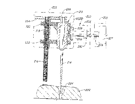
Referring now to FIG. 10, yet another alternate
pmhor~ nt of the handpiece of the present invention is
illustrated and generally designated by the numeral 200.
The handpiece 200 includes a head portion 202, a shank
portion 204 and a drive portion 205. A rotary drive 207
within the drive portion 205 rotates a drive shaft 206
which has a beveled gear 208 connected thereto. The
beveled gear 208 engages the beveled gear 212 of a chuck
assembly 210. The chuck as6embly 210 is substantially
identical to the chuck assemblies 42 and 108 described
above in connection with the handpieces 10 and 100. An
endodontic file 214 is latched in the chuck assembly 210.
Instead of a cylindrical retractable support rod
having the endodontic file 214 disposed therein, the
handpiece 200 in~ P~ a solid support rod 216 which is
positioned parallel to the axis of and adjacent to the file
214. As illustrated in FIG. 10, the support rod 216 is
close to the file 214 whereby it can rest on a surface of
a tooth which is close to or contains the root canal which
is to be cleaned and enlarged by the f ile 214 . The support
rod 216 includes external threads and is threadedly engaged
2 7 84329
--13--
within a cylindrical threaded member 218 which is journaled
within the head portion 202 by a pair of bearings 220 and
222. A rotary gear 224 is connected to the top end of the
threaded cylinder 218 which is engaged with a gear member
226 attached to and a part of the chuck assembly 210.
Thus, when the chuck as6embly 210 i5 rotated by the rotary
drive 207 of the handpiece 200, the threaded cylindrical
member 218 is also rotated at a fixed lower speed. A
spring loaded friction clutch 230 is connected in the shaft
206 so that if the support rod is retracted to its full
extent, the clutch will slip and thereby prevent damage to
the handpiece .
In operation of the handpiece 200, the support rod 216
is extended either manually or by operating the drive of
the handpiece 202 in reverse while holding or otherwise
maintaining the support rod 216 stationary. Once the
support rod 216 has been extended, the handpiece 200 is
positioned with the support rod 216 resting on a tooth 232
and with the file 214 positioned to enter a root canal 234
to be cleaned and enlarged as shown in FIG. 10. After
positioning the handpiece, the handpiece drive 207 is
activated which causes the file 214 to be rotated at a
predet~rm; nf~d speed in the range of from about 30 to about
3000 rpm and the support 216 to be retracted whereby the
file 214 is advanced in the root canal 234 at a rate in the
range of from 0 . 001 to 0 .1 millimeters per revolution of
the file 214. In using the handpiece 200 or the handpieces
10 and 100 described above, when the first endodontic file
is fully inserted in the root canal and has partially
cleaned and enlarged the root canal, the drive of the
handpiece is stopped, the file is replaced with the next
larger size file and the above described procedure is
repeated whereby the endodontic file is advanced into the
root canal at a controlled rate and excessive loading of
2 1 843Z9
the file does not occur. Additional larger files are
successively utilized until the root canal i5 fully cleaned
and enlarged whereby it can be f illed with a hardenable
composition such as gutta percha.
As will now be understood by those skilled in the art,
the improved handpiece of the present invention can include
various combinations of apparatus which utilize various
control techniques, etc. However, in whatever form the
apparatus takes, it includes a rotary drive which rotates
a chuck for holding and rotating an endodontic file, and a
retractable support rod i6 positioned adjacent and
substantially parallel to the endodontic file. The support
rod which can itself take various forms is adapted to rest
on a tooth whereby its retraction controls the advance of
the endodontic file into a root canal to be cleaned and
enlarged. Apparatus is attached to the handpiece for
controlling the retraction of the support rod and the
advance of the rotating endodontic file at a controlled
rate whereby the endodontic file does not self thread into
the canal or otherwise become excessively loaded while the
root canal is being cleaned and enlarged.
In carrying out the methods of this invention
utilizing the ; ~ Luv~d handpiece of this invention, an
endodontic file is first connected to the rotatable chuck
of the handpiece. The handpiece is placed with the
endodontic file positioned to enter a root canal of a tooth
and with the movable support rod of the handpiece resting
on a tooth . The endodontic f ile i5 rotated at a 6peed
sufficient to clean and enlarge the root canal when the
file is advanced into the root canal, and the support rod
is moved whereby the endodontic file is advanced into the
root canal at a controlled rate so that the endodontic file
does not become excessively loaded while the root canal is
being cleaned and enlarged.
2 1 84329
--15--
The present invention, therefore, is well adapted to
meet the needs recited above and to carry out the objects
and attain the ends and advantages mentioned as well a6
those inherent therein. While numerous changes can be made
in the construction and arrangement of parts, such changes
are encompassed within the spirit of this invention as
defined by the ~rpPn~ claims.