Language selection

Search

Patent 2184571 Summary

Third-party information liability

Some of the information on this Web page has been provided by external sources. The Government of Canada is not responsible for the accuracy, reliability or currency of the information supplied by external sources. Users wishing to rely upon this information should consult directly with the source of the information. Content provided by external sources is not subject to official languages, privacy and accessibility requirements.

Claims and Abstract availability

Any discrepancies in the text and image of the Claims and Abstract are due to differing posting times. Text of the Claims and Abstract are posted:

  • At the time the application is open to public inspection;
  • At the time of issue of the patent (grant).
(12) Patent: (11) CA 2184571
(54) English Title: A FIRE FIGHTING INSTALLATION FOR DISCHARGING A LIQUID-GAS FOG
(54) French Title: DISPOSITIF DE LUTTE CONTRE L'INCENDIE CONCU POUR DECHARGER UN BROUILLARD DE LIQUIDE-GAZ
Status: Expired and beyond the Period of Reversal
Bibliographic Data
(51) International Patent Classification (IPC):
  • A62C 35/02 (2006.01)
  • A62C 31/00 (2006.01)
  • A62C 35/62 (2006.01)
  • A62C 99/00 (2010.01)
(72) Inventors :
  • SUNDHOLM, GORAN (Finland)
(73) Owners :
  • MARIOFF CORPORATION OY
(71) Applicants :
  • MARIOFF CORPORATION OY (Finland)
(74) Agent: KIRBY EADES GALE BAKER
(74) Associate agent:
(45) Issued: 2005-09-27
(86) PCT Filing Date: 1995-04-13
(87) Open to Public Inspection: 1995-10-26
Examination requested: 2002-03-07
Availability of licence: N/A
Dedicated to the Public: N/A
(25) Language of filing: English

Patent Cooperation Treaty (PCT): Yes
(86) PCT Filing Number: PCT/FI1995/000215
(87) International Publication Number: WO 1995028204
(85) National Entry: 1996-08-30

(30) Application Priority Data:
Application No. Country/Territory Date
941738 (Finland) 1994-04-14
942534 (Finland) 1994-05-30

Abstracts

English Abstract


The object of the invention is to
provide a novel fire-fighting installation
enabling effective delivery of liquid with
immediate effective mixing of gas into
the liquid right from the start. This is
achieved by connecting to an outlet line
(2) of a hydraulic accumulator (1, 1a) at
least one compressed-gas bottle (4) in the
way of a communicating vessel.


French Abstract

L'invention concerne un nouveau dispositif de lutte contre l'incendie permettant la décharge efficace de liquide avec mélange efficace immédiat du gaz dans le liquide dès le déclenchement du dispositif. Pour ce faire, une ligne de sortie (2) d'un accumulateur hydraulique (1, 1a) est raccordée à au moins une bouteille de gaz comprimé (1) de la même manière qu'un vase communicant.

Claims

Note: Claims are shown in the official language in which they were submitted.

6
CLAIMS:
1. A fire-fighting installation comprising a
liquid source and a gas source connected by way of a
line to an outlet line of the liquid source for
mixing gas with outbound extinguishing liquid
delivered to spray heads, whereby the liquid source
comprises a hydraulic accumulator having at least one
liquid tank, and that the gas source comprises at
least one compressed-gas vessel connected to the
liquid tank in such a way that the compressed-gas
vessel and liquid tank form communicating vessels,
the compressed-gas vessel being adapted to mix gas
into the extinguishing liquid delivered to the spray
heads to produce a finely divided liquid mist,
characterized in that a compressed-gas container is
coupled to the liquid tank for driving out liquid
from said at least one liquid tank, the compressed-
gas vessel forming communicating vessels with the
liquid tank and gas source.
2. An installation as claimed in claim 1,
characterized in that the compressed-gas container
and compressed-gas vessel have substantially the same
initial charge pressure.
3. An installation as claimed in claim 2,
characterized in that the initial charge pressure of
the compressed-gas container is 100-200 bar.
4. An installation as claimed in claim 1,
characterized in that the initial charge pressure of
the compressed-gas container is higher than that of
the compressed-gas vessel.
5. An installation as claimed in claim 1,
characterized in that a valve is incorporated in the

7
outlet line of the liquid source for activating and
alternatively shutting off the installation dependent
on the operating position of the valve.

Description

Note: Descriptions are shown in the official language in which they were submitted.


CA 02184571 2005-O1-04
1
A FIRE FIGHTING INSTALLATION FOR DISCHARGING A
LIQUID-GAS FOG
The present invention relates to a fire-
s fighting installation comprising a liquid source and
a gas source connected by way of a line to an outlet
line of the liquid source for mixing gas with
outbound extinguishing liquid delivered to spray
heads.
Certain kinds of gasoline fires, for example a
kerosene fire in an aircraft jet engine undergoing an
engine test in a hangar designed for that purpose,
are nearly impossible to extinguish even by means of
strong mist-like jets of liquid, as suggested for
example in CA 2,103,069. Such a jet engine fire will
only go out when the entire hangar, which may
typically have a volume of about 3000 m3, has been
subjected to "total flooding", i.e. is in practice
entirely filled with liquid mist having very small
particles.
The liquid mist can in principle be produced
with apparatus as described in CA 2,123,706. In that
application, an outgoing ascension tube of a
hydraulic accumulator is provided with wall
apertures, so that the propellent gas of the
accumulator initially drives out liquid only, and
after the liquid level has sunk to be even with the
uppermost tube wall aperture, mixing of gas into the
outbound liquid is gradually started as the liquid
level sinks and more tube wall apertures are exposed.
In the final stage of emptying the accumulator, it is
possible to obtain a liquid mist having sufficiently
small droplets for the present purpose, but too large

CA 02184571 2005-O1-04
la
a portion of the liquid contained in the hydraulic
accumulator will go waste.
It is an object of the present invention to
provide a novel installation enabling effective

CA 02184571 2005-O1-04
2
delivery of liquid with immediate effective mixing of
gas into the liquid right from the start.
The installation in accordance with the inven
tion is characterized in that the liquid source com
prises a hydraulic accumulator having at least one
liquid tank, and that the gas source comprises at least
one compressed-gas vessel connected to the liquid tank
in such a way that the compressed-gas vessel and liquid
tank form communicating vessels, the compressed-gas
vessel being adapted to mix gas into the extinguishing
liquid delivered to the spray heads to produce a finely
divided liquid mist.
A preferred embodiment of the invention is
characterized in that a compressed-gas container is
coupled to the liquid tank for driving out liquid from
said at least one liquid tank, the compressed-gas
vessel forming communicating vessels with the liquid
tank and the compressed-gas source.
The proportion of gas mixed into the extin-
guishing liquid is determined by the proportion of the
volumes of the propellant gas container of the liquid
source and the compressed-gas container of the gas
source.
- If the propellant gas container of the liquid
source and the gas source have the same initial charge
pressure, gas is mixed into the extinguishing liquid
from the start. If the propellant gas container of the
liquid source has a higher initial charge pressure than
the gas source, only liquid is discharged from the
spray heads in a first step, until the pressure in the
propellant gas container of the liquid source has
decreased to equal the pressure of the gas source.
In the following the invention will be

~
CA 02184571 2005-O1-04
3
described with reference to the accompanying drawing
showing two preferred embodiments of the installation
in accordance with the invention.
Figure 1 shows an embodiment having separate
sources for propellant gas and gas to be mixed into the
extinguishing liquid.
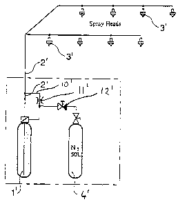
Figure 2 shows an embodiment in which a common
source for propellant gas and gas to be mixed into the
extinguishing liquid is provided.
The embodiment shown in Figure 1 comprises a
hydraulic accumulator, having an outlet line 2 leading
to a plurality of spray heads 3 via a valve 12. A com-
pressed-gas container in the form of a compressed-gas
bottle 4 is connected to the outlet line 2 by way of a
line 10. The hydraulic accumulator incorporates two
liquid tanks 1, the outlet tubes of which may be pro-
vided with apertures,. as in CA 2,123,706, and a
propellant gas bottle la.
The liquid tanks 1 may contain for example
water. The liquid is driven out from the tanks 1 by
means of propellant gas delivered from the propellant
gas bottle la.
The propellant gas bottle la may, be filled
with nitrogen, argon, air, etc. In principle, any suit
able gas can be used. The initial charge pressure of
the propellant gas bottle la is for instance 100-200
bar. The compressed-gas bottle 4 may contain nitrogen,
argon, air, etc. In principle, any suitable gas is
possible. The initial charge pressure of the propellant
gas bottle la is the same or higher than the initial
charge pressure of the compressed-gas bottle 4. The
contents of the propellant gas bottle la and com-
pressed-gas bottle 4 may be partially in liquid form,
depending on the type of gas employed.

2~84~i1
WO 95/28204 PCT/FI95/00215
4
The liquid tanks 1, propellent gas bottle la
and compressed-.gas bottle 4 form communicating vessels,
and thus the emptying of each will be automatically
continued until all liquid has been driven out. The
proportion of gas to be mixed from bottle 4 is '
dependent on the ratio between the volumes of the
propellent gas bottle la and the compressed-gas bottle
4. The quantity of liquid relative to the quantity of
propellent gas determines the length of the flow; the
more liquid, the longer the flow and the lower the
final pressure in the propellent gas bottle la and the
compressed-gas bottle 4.
Figure 2 shows another embodiment of the
installation of the invention. This embodiment differs
from the embodiment of Figure 1 mainly in that the pro
pellent gas source for driving liquid out of the liquid
tank 1' and the compressed-gas source for mixing gas
into the liquid in the line 2' are constituted by the
same source 4'. This source is a compressed-gas bottle
4' filled with nitrogen and having an initial charge
pressure of approximately 100-200 bar. A line 10' has
been coupled between the compressed-gas bottle 4' and
the outlet line 2' of the liquid tank 1'.
In the embodiment of Figure 2, valve 12' has
been connected between the throttle 11' and the com
pressed-gas bottle 4' for activating and alternatively
passivating the installation. The valve could, however,
be connected directly to the line 2', as in Figure 1.
The purpose of the throttle 12' is to induce
a comparatively large gas flow from the compressed-gas
bottle 4' to the liquid tank 1' by choking the gas
flow, in which situation the gas flow from the throttle .
directly to the outlet line 2' is relatively small. In
this situation, the throttle 12' adjusts the mixing
ratio of liquid and gas in the extinguishing fluid

2184571
WO 95/28204 PCT/FI95/00215
gushing into the outlet line 2' . The throttle 12' is
not indispensable. It could be contemplated that the
mixing ratio couldlbe adjusted by the dimensioning of
the line between branching point 13' and the outlet
~ 5 line 2'.
The invention has been illustrated in the
above by way of examples, and it is therefore to be
noted that the invention can vary in its details in
many ways within the scope of the appended claims.
Hence, for example, any compressed-gas vessel may be
employed as a compressed-gas bottle 4, 4' . The number
of compressed-gas vessels and compressed-gas containers
may vary.

Representative Drawing
A single figure which represents the drawing illustrating the invention.
Administrative Status

2024-08-01:As part of the Next Generation Patents (NGP) transition, the Canadian Patents Database (CPD) now contains a more detailed Event History, which replicates the Event Log of our new back-office solution.

Please note that "Inactive:" events refers to events no longer in use in our new back-office solution.

For a clearer understanding of the status of the application/patent presented on this page, the site Disclaimer , as well as the definitions for Patent , Event History , Maintenance Fee  and Payment History  should be consulted.

Event History

Description Date
Time Limit for Reversal Expired 2013-04-15
Letter Sent 2012-04-13
Inactive: IPC deactivated 2011-07-29
Inactive: IPC from MCD 2010-02-01
Inactive: IPC expired 2010-01-01
Grant by Issuance 2005-09-27
Inactive: Cover page published 2005-09-26
Pre-grant 2005-07-14
Inactive: Final fee received 2005-07-14
Notice of Allowance is Issued 2005-04-22
Letter Sent 2005-04-22
Notice of Allowance is Issued 2005-04-22
Inactive: First IPC assigned 2005-04-21
Inactive: Approved for allowance (AFA) 2005-03-31
Amendment Received - Voluntary Amendment 2005-01-04
Inactive: S.30(2) Rules - Examiner requisition 2004-07-08
Letter Sent 2002-04-09
Inactive: Status info is complete as of Log entry date 2002-04-09
Inactive: Application prosecuted on TS as of Log entry date 2002-04-09
Inactive: Entity size changed 2002-04-05
Amendment Received - Voluntary Amendment 2002-03-07
Request for Examination Requirements Determined Compliant 2002-03-07
All Requirements for Examination Determined Compliant 2002-03-07
Letter Sent 2001-11-05
Application Published (Open to Public Inspection) 1995-10-26

Abandonment History

There is no abandonment history.

Maintenance Fee

The last payment was received on 2005-03-29

Note : If the full payment has not been received on or before the date indicated, a further fee may be required which may be one of the following

  • the reinstatement fee;
  • the late payment fee; or
  • additional fee to reverse deemed expiry.

Please refer to the CIPO Patent Fees web page to see all current fee amounts.

Owners on Record

Note: Records showing the ownership history in alphabetical order.

Current Owners on Record
MARIOFF CORPORATION OY
Past Owners on Record
GORAN SUNDHOLM
Past Owners that do not appear in the "Owners on Record" listing will appear in other documentation within the application.
Documents

To view selected files, please enter reCAPTCHA code :


To view images, click a link in the Document Description column. To download the documents, select one or more checkboxes in the first column and then click the "Download Selected in PDF format (Zip Archive)" or the "Download Selected as Single PDF" button.

List of published and non-published patent-specific documents on the CPD .

If you have any difficulty accessing content, you can call the Client Service Centre at 1-866-997-1936 or send them an e-mail at CIPO Client Service Centre.


Document
Description 
Date
(yyyy-mm-dd) 
Number of pages   Size of Image (KB) 
Representative drawing 1997-10-16 1 9
Claims 1996-08-30 1 57
Cover Page 1995-04-13 1 16
Abstract 1995-04-13 1 45
Claims 1995-04-13 1 48
Description 1995-04-13 5 192
Drawings 1995-04-13 1 17
Claims 2005-01-04 2 44
Description 2005-01-04 6 188
Representative drawing 2005-03-31 1 5
Cover Page 2005-08-30 1 33
Reminder - Request for Examination 2001-12-17 1 118
Acknowledgement of Request for Examination 2002-04-09 1 180
Commissioner's Notice - Application Found Allowable 2005-04-22 1 162
Maintenance Fee Notice 2012-05-25 1 172
PCT 1996-08-30 9 375
Correspondence 2005-07-14 1 30
Fees 1997-03-26 1 67