Note: Descriptions are shown in the official language in which they were submitted.
I
I -'
~..
CA 02184795 2003-10-03
1
A MACHINE FOR TREATING THE BALLAST BED OF A TRACK
The invention relates to a machine for treating the
ballast bed of a track, comprising a machine frame supported
on on-track undercarriages, a suction unit with a vertically
and laterally adjustable sucking tube comprising a suction
opening for removing ballast by suction, and a conveyor belt
arrangement associated with the suction unit for removing the
ballast taken up by suction, a ballast discharge device
following the sucking tube in the working direction and
comprising a charging hopper, and also a track lifting unit.
A machine of this kind is already known from WO 94/17245
and serves to remove by suction or replace the complete
ballast bed of a track. The ballast removed with the
assistance of excavating elements from the region beneath the
sleepers passes via the sucking tube into a ballast store
fixed to the machine frame, the outlet opening of which is
associated with a conveyor belt arrangement. The bedding
ballast removed by suction is conveyed by the said conveyor
belt arrangement to the front end of the machine in the
working direction and is loaded into hopper wagons coupled to
the machine. At the same time new ballast is brought up from
the rear end of the machine, the new ballast being discharged
from hopper wagons by way of the charging hopper of a ballast
discharge device into the track immediately following the
excavating elements. In the discharge region the track is
held in its position in the vertical sense by means of the
lifting unit. Re-use of the old ballast (entirely or even
only partly) is not provided.
A machine for performing the lowering of a track is also
known according to DE 41 O1 432 A1. At the front end, in the
2184795
2
working direction, of the machine frame designed for on-track
travel on running gear is located a track lifting device and
also a vertically adjustable arrangement for removing the
ballast by suction from the track down to a desired level
created by an excavating or grading element. The ballast
passes via a conveyor belt to a charging hopper positioned at
the rear end of the machine. Located therein is a screen for
cleaning the ballast and a conveyor belt for removing the
screened waste. The track panel automatically positions
itself in the region of the rear running gear at the new,
lower ballast bed level and is then filled as required between
the sleepers with cleaned ballast from the charging hopper.
In a final operational step the track is subsequently tamped.
The object of the present invention is now to provide a
machine of the type specified in the introduction, which,
while retaining the known advantages, can also be used to
rehabilitate sections of formation beneath the ballast bed.
This object is achieved with a machine of the type
previously defined which is characterized by a conveyor means,
extending in the longitudinal direction of the machine, which
has an intake end associated with the suction unit and a
discharge end associated with the charging hopper of the
ballast discharge device, the track lifting unit being
positioned between the suction opening and the ballast
discharge device.
With a machine designed in this way, a relatively long
ballast-free region of the track can be created for
rehabilitating sections of formation, while involving only
little extra constructional expense. An advantage here is
that there is no need fir the time-consuming and labour-
intensive temporary storage of ballast briefly removed from
the track in a storage wagon attached to the machine. In
practice, all the ballast can be temporarily stored in the
circuit composed of suction unit, conveyor means and charging
CA 02184795 2003-10-03
3
hopper. Because of the special design of the machine, the
treatment of the exposed formation can take place in a
particularly advantageous manner immediately following the
excavation of the ballast and, concluding the operational use of
the machine, the rehabilitated formation can be immediately
covered with ballast again without special machine movements
being required. Thus the track possession times required for the
rehabilitation can thereby be appreciably decreased, with a
reduction in the machine or vehicle expenditure.
In another aspect, the present invention resides in a
machine having an intake end of the conveyor means provided
underneath a discharge end of the conveyor arrangement.
In a further aspect, the present invention resides in a
machine having respective driver s cabins which are arranged both
at the rear end and the front end of the machine frame in a
working direction.
The invention is described in more detail in the following
with the aid of a drawing, in which:
Fig. 1 and 2 show a side view of the machine which, for
reasons of space, is illustrated in two parts.
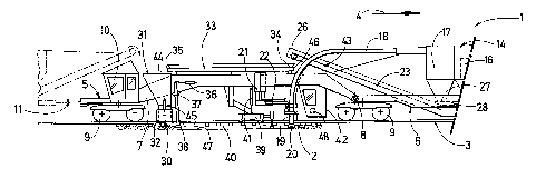
A machine 1 for treating the ballast bed 2 of a track 3 is
shown in Fig. 1 and 2, in which the rear portion of the machine 1
- with respect to a working direction indicated by an arrow 4 -
is reproduced in Fig. 1 and the front portion in Fig. 2. The
machine 1 has an elongated machine frame 5 which is composed of a
front frame part 6 and a rear frame part 7 of recessed design.
The two frame parts 6 and 7 are joined together so as to be
universally mobile by way of a joint 8 and are supported on the
CA 02184795 2003-10-03
r
3a
track 3 by means of three on-track undercarriages 9 altogether at
the two longitudinal ends of the machine frame 5 and in the
vicinity of the joint 8. Also provided at the two longitudinal
ends are respective driver s cabins 10 and buffer couplings 11
for the connection to other track maintenance vehicles. An
engine 12 serves to supply energy to a motive drive 13 as well as
to the other drives and units of the machine 1 yet to be
described.
Located on the front frame part 6 is a suction unit 14
- 2184795
4
which is composed of a vacuum generator 15, a filter chamber
16, a ballast store 17 and two suction hoses 18 opening into
the said ballast store. The free end of each of these suction
hoses 18, which extend approximately parallel to one another
and at a distance apart in the transverse direction of the
machine, is connected to a sucking tube 19, each sucking tube
having a suction opening 20 for removing ballast by suction.
Each sucking tube 19 is fixed, vertically and laterally
adjustably by means of drives 22 with the aid of a guide 21,
to the rear frame part 7 in the recessed region thereof.
A conveyor belt arrangement 23 extends in the
longitudinal direction of the machine underneath the filter
chamber 16 and the ballast store 17 and has an elevated
portion 24 at the front end of the machine. Associated with
this portion is a loading conveyor belt 25 which is mounted on
the machine frame 5 or frame part 6 so as to be displaceable
longitudinally and can be retracted during transfer travel of
the machine 1 into a non-projecting, inoperative position.
The opposite, rear end of the conveyor belt arrangement 23,
with respect to the longitudinal direction of the machine, has
an elevated discharge end 26 which is arranged so as to
project beyond the joint 8 over the rear frame part 7.
Both the ballast store 17 and the filter chamber 16 are
provided on their lower surfaces with discharge openings 27
which are located immediately above the conveyor belt
arrangement 23 and which are closable by way of respective
remotely controllable flaps 28. The conveyor belt arrangement
23 is provided with a rotary drive 29 which is designed for
selective operation or rotation in either direction of
rotation.
Fixed to the rear frame part 7, immediately preceding the
rear on-track undercarriage 9 of the machine 1 in the working
direction, is a ballast discharge device 30 designed as a
ballast hopper which has an upwardly open charging hopper 31
2184795
and discharge chutes 32 located immediately above the track.
Immediately preceding the said discharge chutes is a
vertically adjustable consolidating beam 38 which is pivotable
by way of a drive 36 around a horizontal axis 37 extending in
the transverse direction of the machine. A conveyor means 33
comprising a drive 46 extends along the recessed region of the
frame part 7 and is mounted on the upper surface thereof, an
intake end 34 of the conveyor means 33 being associated with
the discharge end 26 of the conveyor belt arrangement 23. A
discharge end 35 of the conveyor means 33 is positioned over
the charging hopper 31.
Located in the recessed region of the frame part 7,
between the suction openings 20 of the sucking tubes 19 and
the discharge chutes 32 of the ballast discharge device 30
which are situated at a distance from the said suction
openings in the longitudinal direction of the machine, is a
worksite 40, within which a formation 47 is exposed. A track
lifting unit 39, arranged in this region between the suction
opening 20 and the ballast discharge device 30 and connected
vertically adjustably by means of drives 41 to the machine
frame 5 or frame part 7, is located at a distance both from
the suction openings 20 and from the discharge chutes 32.
Also, there is associated with the worksite 40 an operator's
cabin 42 which is joined to the machine frame 5 between the
sucking tubes 19 and the middle on-track undercarriage 9 and
in which there is located a central control unit 48.
The operational use of the machine 1 begins, by the
lowering of the two sucking tubes 19, with ballast being
continuously removed by suction, so that, with the creation of
a worksite 40, a formation 47 is thereby exposed for
treatment. The suspended track 3 is held in the original
position by the track lifting unit 39. As soon as the ,
formation 47 between the two sucking tubes 19 and the
consolidating beam 38 is exposed, treatment of the formation
47 can begin, for example with the machine 1 stationary.
2184795
6
Instead of the formation, a fixed structure, e.g. a bridge,
can of course also be exposed for treatment. When the
rehabilitation operations have been completed, the two sucking
tubes 19 are rendered inoperative by being raised and, with
the machine advancing continuously, the reintroduction of the
ballast is started with the corresponding opening of the
discharge chutes 32. The control of the drives 45 of the
discharge chutes 32 may advantageously be performed by an
operator in the rear driver's cabin 10. In parallel
therewith, the discharged ballast is consolidated by means of
a reciprocal movement of the consolidating beam 38 extending
in the longitudinal direction of the machine.
Apart from the application described, it is of course
also possible for the worksite 40 to move along with the
machine 1 as it continuously advances operationally, i.e. the
front region of the worksite 40 is continuously removed by
suction while ballast is continuously discharged and
consolidated in the rear end region thereof.
If the ballast removed by suction is very heavily
contaminated and is thus no longer reusable, it can be
discharged onto the conveyor belt arrangement 23 and conveyed
by way of the loading conveyor belt 25 to a preceding storage
wagon shown in dot and dash lines in Fig. 2. In parallel
therewith, new ballast from a storage wagon coupled to the
rear end of the machine (see Fig. 1) can be discharged into a
charging opening 44 of the charging hopper 31 and can be
discharged via the discharge chutes 32 in a targeted manner
onto the formation 47. This supply of new ballast may
advantageously also be provided as a means of replenishing the
ballast when the quantity of old ballast removed by suction
and reintroduced by way of the conveyor means 33 is
insufficient.