Note: Descriptions are shown in the official language in which they were submitted.
218~6~
IGNITION CYLINDER ANTI-THEFT SENSOR
CONTACT MECHANISM
Field Of The Invention
s
The present invention relates to automotive anti-theft
systems in general, and more specifically to an improved ignition cylinder
anti-theft sensor contact mechanism.
Back~round Of The Invention
Anti-theft systems for sensing the physical presence, or
absence, of an apparatus typically rely on an electrical circuit having
contacts touching an enclosure, usually connected to ground, which houses
15 the apparatus. For example, a car radio may have a contact thereon
which completes an electlical alarm circuit by touching a frame on an
automotive dashboard into which the radio is inserted, as shown in U.S.
Patent 4,805,233 (Robitschko et al.). Leaf-spring type contacts for
completing an electrical alarm circuit are known which may be attached
20 either to the radio or to the enclosure, such as disclosed in U.S. Patent
4,679,026 (Knakowswi et al.).
Use of a leaf-spring type contact in an anti-theft system to
sense the presence of a lock assembly in a lock housing of an automotive
ignition system was shown in U.S. Patent 4,803,460 (Rhee et al.), assigned
25 to the assignee of the present invention and incorporated herein by
reference. As seen in Fig. 8, the anti-theft system of that patent employs a
resilient contact 124 which is compressed against the internal surface of a
housing 150 when a lock assembly 140 is inserted therein to provide a
continuous ground for a resistor 122 in a circuit (not shown). Upon forced
30 removal of the lock 140 fiom the housing 150. the contact 124 breaks
contact with the housing 150 causing an interruption in the electrical path
218~60
through the resistor 122 and triggering the circuit to activate a
conventional alarm system, for example, an audio or visual alarm.
The contacts in prior apparatus presence sensing anti-theft
systems generally serve both as a mechanical sensor, which senses the
5 physical presence of the apparatus, and an electrical sensor, which
provides electrical continuity or discontinuity to an alarm circuit. One
disadvantage of these sensing assemblies is that the contact surfaces may
be exposed to oil, grease, dirt, and other surface coating substances, thus
inhibiting electrical contact therebetween. In addition, galvanic corrosion,
10 perhaps induced by current flowing through the actuation me(~hAni.sm,
can degrade contact pressure between the contact surfaces when made of
imil~r metals. Either of these problems may trigger false alarms.
A particular problem with anti-theft systems for vehicle
ignitions systems is that they typically are grounded to the steering
5 column casing and require a screw and lug to complete the ground path.
Such a design not only increases assembly and disassembly time, but also
has other disadvantages. For example, the ground path through the
steering column will vary between vehicle models due to tlifferences in
column design, column material properties, and method of attachment to
20 the vehicle, thus requiring accomodation of the screw and lug.
Additionally, the ground impedance provided by the screw and lug may
change over time due to galvanic corrosion or due to the steering column
not adequately connected to the chassis. Finally, the steering column with
a screw and lug or other like system is subject to corrosion and loss of
25 torque on the screw which will cause an open ground circuit and system
failure.
218~186~)
S~lmm~ r~ Of The Invention
The present invention overcomes the disadvantages of the
s related art by providing an anti-theft sensor contact mechanism which
utilizes a non-conducting lever to sense the physical presence of a lock
liner within a lock cylinder and to depress a moveable contact against a
stationary contact of the same metal for closing a path in an electrical
sensing circuit. Electlical continuity between the contacts is enhanced by
o enclosing them within a housing through which the lever protrudes. The
electrical circuit is not grounded through the steering column casting by
the lever or either the stationary or moveable contacts, but is grounded
through continuous wires attached to the contacts.
.~n advantage of the present invention is an anti-theft sensor
contact mechanism which increases contact reliability between the
actuating contacts.
Another advantage is an anti-theft sensor contact mechanism
which is easy to assemble and disassemble.
Still another advantage of the present invention is an anti-
theft sensor contact mechanism which reduces galvanic corrosion between
the contacts.
~ et another advantage is an anti-theft sensor contact
mechanism which is not grounded through the sensor actuating contact to
the steering column casting.
.~ feature of the present invention is a non-conducting
actuation lever which presses a moveable contact into electrical connection
with a stationary contact.
.~nother feature is a sensor housing which isolates the
moveable and stationary contacts from grease, oil, dirt and other debris so
as to maintain electlical contact therebetween.
2184~60
Still another feature of the present invention is an anti-theft
sensor contact mechanism having contacts made of the same metal.
Yet another feature is an anti-theft sensor contact
mechanism having gold plated contacts.
Yet still another features is an anti-theft sensor contact
mechanism which has continuous wires connected to the contacts thereof
so as to eliminate grounding through the steering column casting.
Brief Description Of The Drawin~s
These and other objects, advantages, and features of the
present invention will be apparent to those skilled in the anti-theft system
arts upon reading the following description with reference to the
accompanying drawings, in which:
Fig. 1 is a perspective view of an automotive vehicle steering
column showing an ignition key system and lock cylinder extending
therefrom;
Fig. 2 is an exploded perspective view of an ignition system
having an anti-theft sensor contact mechanism according to the present
invention;
Fig. 3 is a perspective view of a lock liner shown inserted in
the lock cylinder of a steering column casting with an anti-theft sensor
contact mechanism of the present invention attached thereto;
Fig. 4 is a perspective view of an anti-theft sensor contact
mechanism of the present invention;
Fig. 5 is an exploded perspective ~,iew of the mechanism of
Fig. 4;
` - 2184~60
-
Fig. 6 is a cross-sectional view of an anti-theft sensor contact
mechanism according to the present invention with a moveable contact
shown in the undepressed! non-contacting position:
Fig. 7 is a cross-sectional ~,iew .~imil~r to Fig. 6 but shown
s with the moveable contact in the depressed. contacting position; and
Fig. 8 is a cross-sectional view of a plior art anti-theft sensor
contact mechanism.
Detailed Description Of The Preferred Embodiment
Turning now to the drawings, and in particular to Fig. 1
thereof, an automotive vehicle steering wheel 10 is shown in abutting
relationship to a steering column assembly 12 and has a steering shaft 14
extending therefrom for attachment to a steeling gear (not shown). An
15 ignition key system 16 protrudes through the steeling column assembly
12 to prevent ignition of the automobile's engine in absence of a key.
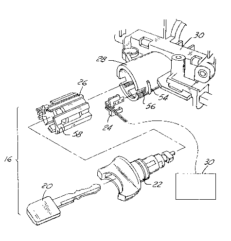
Referring to Fig. 2, the ignition key system 16 contains a steering shaft
locking device (not shown) that retains the steeling wheel 10 in a fixed
position when the ignition is turned off and an ignition key 20 is removed
20 from an ignition lock 22. As will be appreciated by those skilled in the art,and even those not skilled in the art but who have had the unpleasant
experience of having an automobile stolen. thieves may forcibly remove
the steering shaft locking device after gaining entry to the vehicle
passenger compartment in order to release the steeling shaft 14 and
25 thereby allow maneuverability of the vehicle through the steering wheel
10.
The present invention provides an improved anti-theft sensor
contact mechanism 24 which senses the physical presence of a lock liner
26 within the lock cylinder 28 of the steering casting 30 (Fig. 3). When
30 the lock liner 26 is removed. the sensor contact mechanism 24 causes a
break in an electrical path in an electlical monitoring circuit 32 (Fig. 2) so
218~60
that a conventional alarm system (not shown) may be triggered to sound
an audible or visible alarm.
Turning now to Figs. 4 through 7, the sensor contact
me(~h~ni.~m has a housing 34 defining a switching chamber 36 in which
are mounted a stationary contact 38 fixed within the chamber 36 and a
moveable contact 40. The moveable contact 40 is flexibly biased toward a
first position in non-contacting relationship with the stationary contact 38
(Fig. 6) and is moveable to a second position in contacting relationship
with the stationary contact 38 (Fig.7). The housing 34 has a housing top
wall 42 which rests adjacent the lock liner 26 when inserted into the lock
cylinder 28. An opening 44 in the top wall 42 (Fig. 5) allows a lever 46,
which is attached to the moveable contact 40, to extend exteriorly from the
housing 34 (Figs. 4 and 6) so as to be depressed by the lock liner 26 and
thus deflect the moveable contact 40 from the first position (Fig. 6) to the
second position when the lock liner 26 is inserted into the lock cylinder 28
(Fig. 7). The lever 46 is electrically insulated from the moveable contact
40 so as not to conduct electrical current to the lock liner 26.
As seen in Fig. 4, a post 48 extends generally perpendicular
from one end of the housing 34, and a pair of snaps 50 attached to the post
48 extend generally parallel to the housing 34. The snaps 50 each have a
clip 52 which attaches over a flange 54 on an outer surface of the lock
cylinder 28 (Figs. 3 and 6). The post 48 fits into a longitudinal slot 56
(Fig. 2) and is held in place by a knob 58 on the lock liner 26.
The contacts 38, 40 are preferably made of the same metal,
for example stainless steel, to reduce galvanic corrosion. In a preferred
embodiment, the contact surfaces 38', 40' of the contacts 38, 40 (Fig. 7) are
gold-plated to ensure a good contact therebetween and to eliminate
galvanic corrosion.
The stationary contact 38 is preferably insert molded into the
housing 34 along with a resistor 60. Leads 62 of the resistor 60 are
positioned in physical contact with the stationary contact 38 (Fig. 6).
218g~6~
-
Separate conducting wires 64, 66 are connected to the contacts 38, 40,
respectively, as seen in Figs. 6 and 7. The wires 64, 66 are connected with
a monitoring CilCUit 32, such as that described in the aforementioned U.S.
Patent 4,803,460. It will be apparent to those skilled in the art that
s neither the stationary contact 38, the moveable contact 40, or the lever 46
serve as a grounding contact to the steering column, or any other part of
the vehicle.
The just described sensor contact mel~h~ni.sm 24 of the
present invention utilizes a non-conducting lever 46 to sense the physical
o presence of a lock liner 26 within a lock cylinder 28 and to depress a
moveable contact 40 against a stationary contact 38 of the same metal for
closing a path in an electrical monitoring, or sensing, circuit 32. Electrical
continuity between the contacts 38, 40 is enhanced by enclosing them
within a housing 34 through which the lever 46 protrudes to prevent dirt,
grease, oil, and other surface coating debris from inhibiting electrical
contact therebetween. The electrical circuit 32 is not grounded through
the steering column casting 30 through the lever 46 or either the
stationary or moveable contacts 38, 40, but is grounded through
continuous wires 64, 66 attached to the contacts.
Although the preferred embodiment of the present invention
has been disclosed, various changes and modifications may be made
without departing from the scope of the invention as set forth in the
appended claims.