Note: Descriptions are shown in the official language in which they were submitted.
WO 95/24351
2 ~ g 5 Q 9 9 p~~.95,ooog7
Belt having transverse rigidity
The present invention relates to a belt having transverse rigidity in
accordance with the preamble of Claim 1.
A belt of this type having transverse rigidity is disclosed in European
Patent 0 273 478. In the case of said belt, the layers providing transverse
rigidity comprise a number of cables of, for example, four wires each hav-
ing a diameter of 0.6 mm and a spacing of 2.5 mm, located some distance
apart in the horizontal plane. Belts of this type having transverse rigi-
dity are used, for example, as moving pavements in, for example, airports
or exhibition areas. The layers providing transverse rigidity are made of a
high modulus material, for example a material having a modulus greater than
50 Giga Pascal. Examples thereof are steel wire and aramide threads. This
is in contrast to polyester filaments, nylon threads or other relatively
weak materials. One example of a high modulus material is Fleximat~, which
is marketed by the Bekeart Company. A significant advantage of belts of
this type compared with aluminium constructions composed of a large number
of parts is the lower maintenance and the lower noise level. A problem,
which exists with all installations, is the diameter of the drum arounc:
which the belt, or the aluminium pallet system, has to be guided at the
end. If this drum is relatively large, this means that the floor of a buil-
ding in which an installation of this type has to be installed has to be
raised or lowered in order to be able to accommodate the installation and
the associated parts.
In this context a particular advantage of the belt system compared with
the aluminium pallet system is the very small diameter of the drum which
can be used.
Long-term trials with drums having an even smaller diameter have shown
that no problems occur in the short term but in the long term the outer
surfaces of the belt which are subjected to the greatest deformation stress
display cracking. Although such cracking has no significant effect on the
mechanical characteristics of the belt and the latter can still be used for
many years without any problems, a psychological problem with regard to the
reliability of the belt certainly arises when said belts are used for tran-
sporting people. The aim of the present invention is to prevent said crack-
ing in a belt having transverse rigidity.
This aim is achieved in the case of a belt having transverse rigidity,
described above, by means of the characterising measures of Claim 1.
WO 95/24351 PCT/NL95/00087
2
The invention is based on the insight that initiation of the cracks does
not occur at the surface but at the wires which form the layers having
transverse rigidity. Once the cracks have been initiated there, they are
propagated in the direction of the surface of the belt. On the basis of
this insight, in contrast to what would appear to be obvious, no attempt
has been made to take measures to maintain the surface of the belt unda-
waged for a longer period, but measures have been taken to prevent ini-
tiation of the crack at the cables or wires. If there is no initiation at
the cables, the surface of the belt will likewise not crack, so that
special measures at the surface are not necessary.
Once the insight had been gained that the cracks start at the cables,
the following step was to take measures in order to reduce the tension at
the location of the cables. An obvious solution would be simply to increase
the distance between the steel cables. However, this gives rise to the
problem that the transverse rigidity of the belt concerned is reduced. It
would then be possible to use a larger number of wires per cable, but this
gives rise to problems because the risk that the cables will work loose
from the rubber during operation and come to the surface is appreciably
increased. The solution proposed according to the invention, comprising the
arranging of at least two layers of cables some distance apart, makes it
possible to increase the spacing between the cables in each layer while
still using the same amount of cable material in order to provide an
adequate transverse rigidity.
It is pointed out that US Patent 2 850 420 discloses a belt which has a
so-called 'breaker' layer, comprising two sub-layers some distance apart
which provide transverse strength. Here, however, there is no question of
high modulus material, and, therefore, a belt of this type is unsuitable
for use for the transport of, for example, people because this belt will
display appreciable sag. Moreover, this belt does not have a single layer
providing longitudinal strength but a pack of layers, each of which is able
to absorb part of a force acting in the longitudinal direction. Moreover,
one of the sub-layers which provides transverse rigidity is arranged di-
rectly adjacent to such a layer absorbing longitudinal stresses.
Consequently, a belt of this type does not have the desired flexible
characteristics necessary for its movement over a drum of relatively small
diameter, which was precisely what gave rise to the problems on which the
present invention is based.
It is also pointed out that French Patent 72246 discloses a conveyor
PCT/NL 95/00087 2185099
3
belt in which a layer having transverse rigidity is present. Above this
layer a textile layer is provided to prevent the belt from curling during
hardening of the rubber material at fabrication of the belt. This textile
material is, as indicated above, not a high modulus material. Consequently,
cracking will still occur in the case of a belt of this type when the lat-
ter is subjected to load, as according to the invention.
As already indicated above, the consequences of the cracking are most
pronounced at the top of the belt. Therefore, in this case a layer provid-
ing transverse rigidity and composed of at least two sub-layers is arranged
at the top of the belt. In order also to prevent problems on the underside,
the lowest layer providing transverse rigidity can likewise be composed of
at least two sub-layers.
As in the cables used in the prior art, the wires of which the cables
are composed can also consist of high modulus material in the case of the
invention. The distance between the cables is preferably between 2.5 and
7.5 mm. As in the prior art the cables can comprise any number of wires.
For optimum adhesion, preference is given to three wires.
The spacing between two adjacent sub-layers must, on the one hand, be
sufficiently small to be able to maintain the concept of a "box construc-
tion" of the belt but, on the hand, must be sufficiently large that the
crack initiation, described above, in the cables is prevented. It has been
found that these conditions can be met in an optimum manner if the spacing
between the sub-layers is between 1 and 3 mm and preferably about 2 mm.
The layer providing longitudinal strength can, as is generally known, be
arranged in any position between the two layers providing transverse rigi-
dity. However, preference is given to arranging said layer approximately in
the centre of the belt.
The invention will be explained in more detail below with reference to
an illustrative embodiment shown in the drawing. In the drawing:
Fig. 1 shows a partially exposed perspective view of the belt according
to the invention;
Fig. 2 shows a cross-section along the line II-II in Fig. 1 and
Fig. 3 shows, in detail, a longitudinal section along the line III-III
of one of the layers providing transverse rigidity.
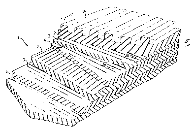
In Fig. 1 the belt according to the invention is indicated in its
entirety by 1. As can also be seen from Fig. 2, said belt comprises a rub-
ber support material 2, which extends over the entire height of the belt.
At the top, said rubber material is constructed as a ribbed profile 8. The
Substitute sheet dated March 14, 1996
AMENDED SHEET
WO 95/24351 2 ~ 8 5 0 9 9 P~'~N1~95/00087
4
following layers are arranged in said rubber support, working from top to
bottom:
two sub-layers 3 and 4, which together form the uppermost layer having
transverse rigidity. In this illustrative embodiment, said sub-layers are
approximately 2 mm apart. The distance between the uppermost part of the
rubber profile 8 and layer 3 is about 8 mm. The di$tance between layers 9
and 5 is between 6 and 15 mm. The two sub-layers..5 and 6 form the
bottommost layer having transverse rigidity. In this illustrative embodi-
ment, said sub-layers are approximately 2 mm apart. On the underside, the
belt is bound by 2 mm rubber. Consequently, the belt has a total thickness
which is preferably between 20 and 35 mm.
Fig. 3 shows a longitudinal section of a layer having transverse rigi-
dity. It can be seen that said layer is composed of cables 9, which are
located in the layers 3 and 4. The spacing of the cables 9 in a layer is
between 2.5 and 7.5 mm and is preferably about 4 mm. Each cable 9 is pre-
ferably composed of three wires 10 of high modulus material. The diameter
of each wire is about 0.6 mm.
The mechanical characteristics of a layer of this type which has trans-
verse rigidity and is made up of two sub-layers can be compared with a
conventional layer having transverse rigidity which is composed of a single
layer containing cables having four wires 0.6 mm in diameter and a pitch of
2.5 mm. The amount of steel or other high modulus material incorporated in
a layer of this type having transverse rigidity is the same as in the case
of the layer having transverse rigidity according to the invention, and the
strength is therefore the same. The invention is based on the insight that
by increasing the spacing between the cables the damping and absorbing
characteristics of the rubber material can be exploited to an optimum
extent and crack initiation is prevented. In the case of the use of three
wires, there is optimum adhesion between rubber and cable.
With reference to Fig. 2, two preferred embodiments of the belt accord-
ing to the invention will be described in more detail below.
Example I:
In the case of a belt having a total thickness of 30 mm, the height of
the ribs is 5.0 mm. This is indicated by A. The distance between layer 3
and the lower part of the longitudinal ribs is indicated by B and is 3.3
mm. With this embodiment, distance C between the two layers 3 and 4 is 2.2
mm, whilst layer 7, which provides the longitudinal strength, is located
2aS5099
WO 95124351 PCT/NL95/00087
approximately in the centre of the belt depth, the height of longitudinal
ribs 8 then no longer being taken into account.
With this embodiment, the distance D + E, i.e. the distance between the
two closest layers providing transverse strength, is 14 mm. The distance
5 between the layers 5 and 6, distance F, is 2.2 mm, whilst the distance G is
2.6 mm.
Example 2:
In this example, the belt is thinner, with a thickness of 24 mm.
In an embodiment of this type, all values are equal to those described
above except for the sum of the values D + E, which in this case is 14 mm.
It can be seen from the above examples that the distance between the
layers 4 and 5 makes up at least 25~ of the total belt thickness (in which
the height of the ribs 8 is not included).
Although the invention has been described above with reference to a
preferred embodiment, it must be understood that numerous modifications can
be made thereto without going beyond the scope of the present invention.
For instance, it is possible to arrange the layer providing longitudinal
strength in a different position, for example adjacent to the lowermost or
uppermost layer providing transverse rigidity. Similarly, the cables can be
composed of a number of wires other than three and each layer providing
transverse rigidity can be composed of three or more sub-layers. All such
modifications are considered to fall within the scope of the appended
claims.