Language selection

Search

Patent 2185106 Summary

Third-party information liability

Some of the information on this Web page has been provided by external sources. The Government of Canada is not responsible for the accuracy, reliability or currency of the information supplied by external sources. Users wishing to rely upon this information should consult directly with the source of the information. Content provided by external sources is not subject to official languages, privacy and accessibility requirements.

Claims and Abstract availability

Any discrepancies in the text and image of the Claims and Abstract are due to differing posting times. Text of the Claims and Abstract are posted:

  • At the time the application is open to public inspection;
  • At the time of issue of the patent (grant).
(12) Patent Application: (11) CA 2185106
(54) English Title: DEVICE FOR CARRYING A WEIGHT
(54) French Title: DISPOSITIF PERMETTANT DE PORTER UNE CHARGE
Status: Deemed Abandoned and Beyond the Period of Reinstatement - Pending Response to Notice of Disregarded Communication
Bibliographic Data
(51) International Patent Classification (IPC):
  • F16M 13/04 (2006.01)
(72) Inventors :
  • HELLSTEN, JOHAN (Sweden)
(73) Owners :
  • JOHAN HELLSTEN
(71) Applicants :
  • JOHAN HELLSTEN (Sweden)
(74) Agent: MARKS & CLERK
(74) Associate agent:
(45) Issued:
(86) PCT Filing Date: 1995-03-21
(87) Open to Public Inspection: 1995-09-28
Availability of licence: N/A
Dedicated to the Public: N/A
(25) Language of filing: English

Patent Cooperation Treaty (PCT): Yes
(86) PCT Filing Number: PCT/SE1995/000285
(87) International Publication Number: WO 1995025926
(85) National Entry: 1996-09-09

(30) Application Priority Data:
Application No. Country/Territory Date
9400979-2 (Sweden) 1994-03-24

Abstracts

English Abstract


The present invention relates to an arrangement for carrying loads, particularly a
camera, on a first shoulder. The arrangement comprises a hip-belt (3), a support beam
(1) extending upwardly from the rear of the hip-belt, a boom (2) pivotably arranged
on and extending out from the upper part of the support beam, and a pre-tensioned,
extensible cord (11) or ribbon, stretching from the free end of the boom for connection
to the load. The invention is characterized in that a shoulder-strap (4) extends from the
hip-belt (3), over the wearer's shoulder and to the support beam (1), and that the cord
runs inside the boom (2).


French Abstract

Dispositif permettant de porter une charge, telle qu'une caméra, sur une épaule. Le dispositif comprend une ceinture enserrant la taille (3), un bras (1) s'étendant vers le haut à partir de la partie postérieure de cette ceinture, une tige (2) montée pivotante à partir de l'extrémité supérieure du bras, et un câble extensible (11) précontraint, s'étendant de l'extrémité libre de la tige, pour être raccordé à la charge. L'invention se caractérise par le fait qu'une brettelle (4) s'étend de la ceinture enserrant la taille (3) par dessus l'épaule de l'utilisateur en direction du bras (1) et par le fait que le câble se dévide à l'intérieur de la tige (2).

Claims

Note: Claims are shown in the official language in which they were submitted.

CLAIMS
1. An arrangement for carrying loads, particularly a camera, on a
first shoulder, comprising a hip-belt, a support beam extending upwardly
from the rear of the hip-belt, a boom pivotably arranged on and extending
out from the upper part of the support beam, and a pre-tensioned,
extensible cord, or a ribbon, stretching from the free end of the boom for
connection to the load to relieve its weight, c h a r a c t e r i z e d i n t h a t
a shoulder-strap extends from the hip-belt, over the wearer's other shoulder
and to the support beam, and that the cord runs inside the boom.
2. An arrangement as claimed in claim 1, c h a r a c t e r i z e d i n
t h a t a force-absorbing spring is arranged in the support beam and
connected to the cord in order to achieve said pre-tension in the cord.
3. An arrangement as claimed in any of the preceding claims,
c h a r a c t e r i z e d i n t h a t a pivotable support is arranged at thelower, free end of the support beam, so that when the support is applied
against a counter surface it relieves the weight from the hip-belt.
4. An arrangement as claimed in any of the preceding claims,
c h a r a c t e r i z e d i n t h a t the hip-belt is displaceably secured to the
support beam.
5. An arrangement as claimed in any of the preceding claims,
c h a r a c t e r i z e d i n t h a t the shoulder-strap is displaceably secured
to the support beam.
6. An arrangement as claimed in either of claims 4 or 5,
c h a r a c t e r i z e d i n t h a t a cushion is arranged at the attachment of
the shoulder-strap to the support beam.
7. An arrangement as claimed in any of the preceding claims,
c h a r a c t e r i z e d i n t h a t the cord runs from the force-absorbing
spring, inside the support beam, over a first pulley, through the boom, over
a second pulley and to the camera.

Description

Note: Descriptions are shown in the official language in which they were submitted.


U M I U ME ~ A EI
ID 46 90 1 266el3 SI D 5
--woss/zss26 2 1 85 1 06 ~ 021iS
De~rice for carrying a ~eigh~ .
TECH~CAI, FIELD
The present invention relates to an arrangement for carrying loads,
particularly a camera, on a first shoulder. The arrangement is of the type
eo~ isinO a hip belt, a support beam extenting upwardly from the rear of
the hi~belt, a boom pivotably arranged on and extendinO out from the
upper part of the support beam, and a pre-tensioned, extensible cort or
ribbon, stretching ~rom the free end of the boom for connection to the load.
BACKGROU~D ART
~Iodern man is now usually no longer in top physlcal condition The
natural exercising of muscles and joints resul~ing from the daily struOgle of
previou5 generations for sun~ival i5 no longer applicable. Motern tools are
not al~ays ergonolnically desi3ned. Take the example of a TV
yhotoOrapher with his camera held on his shoulder. Carrying a c~mera on
one shoulder causes an une~en load on. the spine.
A knot~ n deYicc (see SU A 1~2~660) sho--~s an arran~ement for holding A
h~nd camera. Ho-~ever, this arrangement cannot be used by a
photograyher usinO a shouldes camera since it cannot be used on top of a
shoulder-strap, at least not ~-ithout consiaerable motification of the desi,,n.This arrangement is cumb_,~G",e, hea~y and Iacks stability and good ~eight
distnbution.
. . .
SU~ ARY OF THE I~VE~IO~I
The present in~ention aims at a solution of the problems mentioned above
and associated problems. It is characterizet in that a shouIder-strap extends
from the hip-~oelt, o~er the wearer's shoulter and to the support beam, and
that the cord runs inside the ~OOM. An arrangement is thus obtained that
effecti-~ely retuces the loat on the sho~lder ant transfers the load to the
hips cr to a stationary object. A stable, balanced arrangement is obtained,
close to the body, since the cord is carried internally in the arranc,ement.
. .
In a preferred embodiment a force-absorbing sprin~ is arran~ed in the
supyort beam ant connected to the cord irl order to achieve said pre-tension
in the cord.
`.ORRECTED

W09S12S926 2 1 85 1 06 ~ r~
;z
The i~ ,-lion allows the use of only onc shoulder-strap, the sole ~o~e
of which is to retain the s~ ,vrt beam in ~ertical fJG~ and doff not take
the weight off the hips.
BREF DESW~ J OF THE DRA~INGS
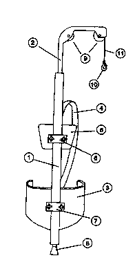
The ~ , drawDg, Fi~ 1, illustrates the inv~..lio,~.
r~c~r~ EMBODIME~T .
~e ~l,~n~ t is designed to be carnet by onl~ onc person. A ~ le
plate i5 also pro~ided at the bolt~l~. of the ar,.-.4~.,.e..t, fn or~er to relie~e
~ ~i8ht from the hiE~belt.
I~e pivotable plate rotates.
~:igure 1 shows a c~rS),il,~ arrangement wi~ a support beam ~1) with
~h,ot~W~ ap~ boom~Z). It also iT~ Ps a load-absG~ elt 13)
and a vertically displaceable att~l....P ~t (6) for a sho~ er-strap (4) and a
c~lCIlion ~5). It also includes a lower, ~icFI- e~l~le athchment (7) in ~hich
the ~ing belt is sc.~.
(8) is a pivobble end ~-lp~v~l for the ~up~v~l beam (1). Thn,~h the boom
e), pi~ots~ly jo~ erl in the ~- p~ eam (1), runs the weight ~;3G~
cord or ribbon (11), Y~ 8 over t~vo jo~rn~lled pulleys (9) for the
cord/nbbon. An stt -h~ent means (10) is loc~ted at the end of the
cord/nbbon, to which the object to be camet Qn be ~e~ur~.l. The other end
of the co~ }*on is secured in the lQrC~_~30~ , Sprirl~ locate~.she
~o,t beam. The spnng may ~e either a gas spnng or a steel sp~ng
A weight, 5uch as a TV ca4._~d, is ~ntPn~le~ to be secured in the hook (10)
attachet in the cor~. The back cushion (5) can be u~ on the ~ t
beam (1). When the su~orl beam is fittet onto a person, ~e operator can
move ~reely whether the hook is loaded or not. The ~dght is t~uf~is~ ~ to
the auppOll belt t3)- When the hook (10) is loaded with ~.;O~ d~ ~le tension
from ~e spring the weight~ e g. a TV c~u~ , can easily be lo-~e.~ or r~ised
The in~ention can be varied in many ways wiWn the scope of the
appende~ rlai~s

Representative Drawing
A single figure which represents the drawing illustrating the invention.
Administrative Status

2024-08-01:As part of the Next Generation Patents (NGP) transition, the Canadian Patents Database (CPD) now contains a more detailed Event History, which replicates the Event Log of our new back-office solution.

Please note that "Inactive:" events refers to events no longer in use in our new back-office solution.

For a clearer understanding of the status of the application/patent presented on this page, the site Disclaimer , as well as the definitions for Patent , Event History , Maintenance Fee  and Payment History  should be consulted.

Event History

Description Date
Time Limit for Reversal Expired 1999-03-22
Application Not Reinstated by Deadline 1999-03-22
Deemed Abandoned - Failure to Respond to Maintenance Fee Notice 1998-03-23
Application Published (Open to Public Inspection) 1995-09-28

Abandonment History

Abandonment Date Reason Reinstatement Date
1998-03-23
Owners on Record

Note: Records showing the ownership history in alphabetical order.

Current Owners on Record
JOHAN HELLSTEN
Past Owners on Record
None
Past Owners that do not appear in the "Owners on Record" listing will appear in other documentation within the application.
Documents

To view selected files, please enter reCAPTCHA code :


To view images, click a link in the Document Description column. To download the documents, select one or more checkboxes in the first column and then click the "Download Selected in PDF format (Zip Archive)" or the "Download Selected as Single PDF" button.

List of published and non-published patent-specific documents on the CPD .

If you have any difficulty accessing content, you can call the Client Service Centre at 1-866-997-1936 or send them an e-mail at CIPO Client Service Centre.


Document
Description 
Date
(yyyy-mm-dd) 
Number of pages   Size of Image (KB) 
Cover Page 1996-12-16 1 14
Abstract 1995-09-28 1 39
Description 1995-09-28 2 95
Claims 1995-09-28 1 42
Drawings 1995-09-28 1 13
Representative drawing 1997-10-21 1 6
Courtesy - Abandonment Letter (Maintenance Fee) 1998-04-20 1 186
Fees 1996-09-09 1 59
International preliminary examination report 1996-09-09 16 524