Note: Descriptions are shown in the official language in which they were submitted.
2 ) 8 5 7 7 3 PATENT
JOINT ASSEMBhY
Background of the Invention
The present invention relates to a new and improved
joint assembly, more specifically, to a joint assembly
having a movable member with a ball end portion disposed in
a housing.
Joint assemblies having movable members with ball end
portions disposed in a housing commonly have a'boot seal
which is connected with the housing and a shank porttion of
the movable member. The boot seal is formed of a f Lexible
material, such as neoprene or urethane. As the movable
member oscillates and/or articulates, the boot seal flexes.
To accommodate movement of the movable member, the boot
seal has a very large profile which limits where the joint
assembly may be installed in a vehicle and allows the seal
to be exposed to road hazards which may puncture or
otherwise damage the seal. In addition, as the boot seal
is repeatedly flexed by relative movement between the
movable member and the housing and is exposed to the
environment, changes may occur'in the properties of the
material forming the seal.
CA 02185773 1999-08-30
- 2 -
Summary of the Invention
The present invention relates to a new and improved joint
assembly which includes a housing and a movable member having a
ball end portion disposed in the housing. An annular seal is
disposed in the housing. The seal includes a metal reinforcing
ring and an annular body of polymeric material which encloses
the metal reinforcing ring.
The body of polymeric material has an outer side surface
which is disposed in sealing engagement with an inner side
surface of the housing. The body of polymeric material also has
an inner side surface which is disposed in sealing engagement
with the ball end portion of the movable member.
The seal has bilateral symmetry about a central plane
extending perpendicular to a central axis of the seal. The
bilateral symmetry enables the seal to be positioned in the
housing with either one of two sides of the seal facing the ball
end portion of the movable member. Thus, the seal has axially
inner and outer halves disposed on opposite sides of the central
plane and having similar configurations. The inner and outer
halves of the body of polymeric material may include radially
inner sides having annular sealing ridges. The annular sealing
ridges are formed by flat annular side surfaces and cylindrical
side surfaces.
According to a first broad aspect, the invention
provides a joint assembly comprising: a housing; a movable
member having a ball end portion disposed in said housing; and a
continuous annular seal disposed between an inner side surface
of said housing anal said ball end portion of said movable
member, said annular seal engaging said inner side surface of
said housing and said ball end portion of said movable member,
said annular seal having a non-circular cross-sectional
CA 02185773 1999-08-30
- 2a -
configuration in an axial plane containing a central axis of
said annular seal and on one side of the central axis, said
annular seal having bilateral symmetry about a central plane
extending perpendicular to the central axis of said annular seal
to enable the annular seal to be positioned in said housing with
either one of two sides of said annular seal facing said ball
end portion of said movable member.
_3_ 2185773
Brief Description of the Drawings
Further features of the present invention will become
apparent to those skilled in the art to which the present
invention relates from reading the following specification
with reference to the accompanying drawings, in which:
Fig. 1 is a fragmentary axial sectional view of a
joint assembly having a seal constructed in accordance with
the present invention; and
Fig. 2 is an enlarged illustration of a portion of the
seal of Fig. 1 prior to installation of the seal in the
joint assembly.
Description of Preferred Embodiment
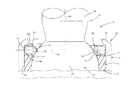
A joint assembly 10 constructed in accordance with the
1
present invention is illustrated in Fig. 1. The joint
1
assembly 10 includes a metal housing 12. The metal housing
12 may be stamped from sheet metal or may be cast as one
piece. The metal housing 12 has a cylindrical side wall 14
with a cylindrical inner side surface 16 which forms a
socket chamber 18. An annular lip 20 is integrally formed
with the side wall 14 and projects radially inward from the
side wall 14.
A movable metal stud member 24 has a ball end portion
26 which is enclosed by the housing 12. The ball end
portion 26 has an outer side surface 28 which is formed as
a portion of a sphere. A shank portion 30 extends outward
'- 2185173
-4-
from the ball end portion 26. The shank portion 30 and
ball end portion 26 are integrally formed as one piece.
A bearing seat 34 supports the ball end portion 26 of
the movable stud member 24. The bearing seat 34 engages
the outer side surface 28 of the ball end portion 26 of the
movable stud member 24. The bearing seat 34 supports the
ball end portion 26 of the movable stud member 24 for
rotational movement about an axis 38.
In addition, the bearing seat 34 supports the movable
stud member 24 for tilting movement from the initial
position illustrated in Fig. 1. The bearing seat 34
supports the movable stud member 24 for tilting movement
about a center of curvature of the ball end portion 26 of
the movable stud member. The shank portion 30 of the
movable stud member 24 can be tilted sideward in any
direction within a 360° range from the position illustrated
in Fig. 1. The bearing seat 34 is formed of a suitable
polymeric material and cooperates with the ball end portion
26 of the movable stud member 24 in a known manner.
An annular seal 42 is constructed in accordance with
the present invention. The seal 42 is enclosed by the side
wall 14 of the housing 12. The annular seal 42 is disposed
axially inward of the annular lip 20. The seal 42 is
disposed in sealing engagement with the inner side surface
16 of the metal housing 12 and~with the outer side surface
28 on the ball end portion 26 of the movable stud member
24.
2185773
-5-
Since the seal 42 is surrounded by the housing 12, it
has a relatively small area of exposure to abrasion,
puncture, or other types of damage by the environment
around the joint assembly l0. Since the seal 42 is
disposed in sealing engagement with the spherical ball end
portion 26 of the movable stud member 24, the movable stud
member can tilt through a large range of movement without
stressing the seal. Since the seal 42 has minimal exposure
to the environment around the joint assembly, the
possibility of seal material variations caused by
contaminants and other environmental factors are minimized.
The annular seal 42 has a non-circular cross-sectional
configuration as viewed in an axial plane (Fig. 1). Thus,
the seal 42 has a generally polygonal configuration then
viewed in a plane which contains the coincident central
axes 38 of the seal and the movable stud member 24. The
central axis 38 of the seal 42 extends through the center
of curvature of the ball end portion 26 of the movable stud
member 24. Of course, the stud member 24 can be tilted so
that its central axis is skewed relative to the central
axis 38 of the seal 42.
The seal 42 has bilateral symmetry about a central or
median plane 46. The central plane 46 extends
perpendicular to the central axis 38 of the seal 42. Since
the seal 42 has bilateral symmetry about the central plane
46, the seal can be positioned with either side of the seal
-6- 2185773
disposed axially inward toward the ball end portion 26 of
the movable stud member 24.
Thus, the seal 42 can be positioned with an upper (as
viewed in Fig. 2) side or half 50 of the seal facing inward
toward the ball end portion 26 of the movable stud member
24 (Fig. 1). The seal 42 can also be positioned with a
lower (as viewed in Fig. 2) side or half 52 of the seal
facing inward toward the ball end portion 26 of the movable
stud member 24 (Fig. 1). This facilitates construction of
the joint assembly 10.
The seal 42 has bilateral symmetry in that it is
divided into an axially outer (Fig. 1) or upper (Fig. 2)
half 50 and an axially inner (Fig. 1) or lower (Fig. 2)
half 52 by the central or median plane 46. The uppejr and
lower halves 50 and 52 (Fig. 2) are counterparts of~each
other. Thus, the upper half 50 of the seal 42 has a
configuration which is a mirror image of the lower half 52
of the seal.
The seal 42 is disposed in sealing engagement with the
bearing seat 34 (Fig. 1). Thus, the seal 42 has a flat
annular inner or lower side surface 56 which is disposed in
tight sealing engagement with a flat annular upper side
surface 58 on the bearing seat 34. The flat annular inner
side surface 56 of the seal 42 and the flat annular upper
side surface 58 of the bearing~seat 34 are coaxial with the
central axis 38 of the seal.
2185713
A cylindrical radially outer side surface 62 of the
seal 42 engages the cylindrical inner side surface 16 of
the housing side wall 14. A fluid tight seal is obtained
between the outer side surface 62 of the seal 42 and the
inner side surface 16 of the housing side wall 14. In
addition, a cylindrical radially outer side surface 64 of
the bearing seat 34 is pressed firmly against the
cylindrical inner side surface 16 of the housing side wall
14.
The annular lip 20 (Fig. 1) on the metal housing 12
presses the annular seal 42 axially inward against the
bearing seat 34. In the embodiment of the joint assembly
10 illustrated in Fig. 1, the continuous annular housing
lip 20 has minimal engagement with the annular seal~42.
However, if desired, the annular housing lip 20 could be
swaged or bent over to provide for abutting engagement
between an inner side surface of the lip and the flat
annular outer side surface 68 of the seal 42 throughout the
extent of the lip. If desired, the housing lip 20 could
have a different configuration. For example, the housing
lip 20 could be formed by a plurality of segments which
extend radially inward from the housing side wall 14.
The axially inner half 52 of the radially inner
portion of the seal 42 sealingly engages the outer side
surface 28 of the ball end portion 26 of the movable stud
member 24. The seal 42 engages the ball end portion 26 of
the stud member 24 at a location which is axially inward of
-8- 2 i 85773
the annular lip 20 and is almost, but not entirely, below
or inward (as viewed in Fig. 1) of the central plane 46
about which the seal 42 has bilateral symmetry.
The seal 42 includes a metal reinforcing ring 72. The
metal reinforcing ring 72 cooperates with the metal housing
12 to resist pullout of the movable stud member 24 from the
socket chamber 18. The seal 42 also includes a body 74 of
polymeric material. The body 74 of polymeric material
encloses the metal reinforcing ring 72 and seals against
the housing 12 and ball end portion 26 of the movable stud
member 24.
The annular metal reinforcing ring 72 (Fig. 2) has a
rectangular cross-sectional configuration as viewed in an
axial plane containing the central axis 38 (Fig. 1) jof the
seal 42. The central plane 46 (Fig. 2) extends through the
center of the rectangular cross-section of the metal
reinforcing ring 72. Although the metal reinforcing ring
72 has been shown in Fig. 2 as having a square cross-
sectional configuration, it is contemplated that the
annular metal reinforcing ring 72 could have a different
cross-sectional configuration.
The annular metal reinforcing ring 72 has a
cylindrical radially outer side surface 80 (Fig. 2) with a
central axis which is coincident with the central axis 38
of the seal 42. In addition, the annular metal reinforcing
ring 72 has a cylindrical radially inner side surface 82
which is coaxial with the cylindrical radially outer side
2851?~
surface 80 of the reinforcing ring 72. When the seal 42 is
installed in the housing 12 (Fig. 1), the cylindrical
radially outer side surface 80 (Fig. 2) and the cylindrical
radially inner side surface 82 of the reinforcing ring 72
are coaxial with the cylindrical inner side surface 16 of
the housing side wall 14. The body 74 of polymeric
material engages the ball end portion 26 of the movable
stud member 24 at a location radially inward of the
reinforcing ring 72.
The metal reinforcing ring 72 has a flat annular
axially outer or upper side surface 86 which extends
between the cylindrical rad~ally outer and inner side
surfaces 80 and 82 of the reinforcing ring. The
reinforcing ring 72 also has a flat annular lower o~ inner
side surface 88 which extends between the cylindrical
radially outer and inner side surfaces 80 and 82. The flat
annular upper and lower side surface 86 and 88 of the
annular metal reinforcing ring 72 extend parallel to the
central plane 46 and perpendicular to the central axis 38
(Fig. 1) of the seal 42. The central plane 46 is disposed
half way between the parallel flat annular outer and inner
side surfaces 86 and 88 on the metal reinforcing ring 72.
The body 74 (Fig. 2) of polymeric material encloses
the reinforcing ring 72 and has bilateral symmetry about
the central plane 46. The cylindrical radially outer side
surface 62 and the body 74 of polymeric material is
disposed in a coaxial relationship with the cylindrical
-10- 218513
radially outer side surface 80 of the reinforcing ring 72.
As was previously mentioned, the cylindrical radially outer
side surface 62 of the body 74 of polymeric material
sealingly engages the inner side surface 16 (Fig. 1) of the
metal housing 12.
The flat annular lower side surface 56 (Fig. 2) and
the flat annular upper side surface 68 on the body 74 of
polymeric material extend parallel to the flat annular
upper side surface 86 and the flat annular lower side
surface 88 of the reinforcing ring 72. In addition, the
flat annular lower side surface 56 and the flat annular
upper side surface 68 of the body 74 of polymeric material
extend parallel to and are spaced equal distances from the
central plane 46.
The bod 74 of
y polymeric material has a radia171y inner
portion 92 (Fig. 2) which sealingly engages the ball end
portion 26 of the movable stud member 24. Upon
installation of the seal 42 in the joint assembly 10, the
radially inner portion 92 of the body 74 of polymeric
material is resiliently deformed by engagement with the
ball end portion 26 of the movable stud member 24.
Assuming that the seal 42 is installed in the housing 12
with the lower half 52 of the seal facing axially inward,
the lower half of the seal is resiliently compressed in a
radially outward direction. Most of the upper half 50 of
the seal 42 retains its original uncompressed
configuration. However, there will be some resilient
-11-
deformation of the upper half of the seal 42 adjacent to
the central plane 46 and adjacent to the housing lip 20.
Prior to installation of the seal 42 in the joint
assembly 10 (Fig. 2), the body 74 of polymeric~material has
bilateral symmetry about the central plane 46. Thus, the
upper half 50 of the body 74 of polymeric material is a
counterpart or mirror image of the lower half 52 of the
body 74 of polymeric material, as viewed about the central
plane 46. This enables the seal 42 to be positioned in the
housing 12 with either side of the seal facing inward
toward the ball end portion 26 of the movable stud member
24. Depending upon which way the seal 42 is installed in
the housing 12, either the upper half 50 or the lower half
52 of the body 74 of polymeric material will have a~fluid
tight seal with the ball end portion of the movable~stud
member 24.
The axially lower half 52 (as viewed in Fig. 2) of the
body 74 of polymeric material includes a plurality of
annular seal ridges or corners 100, 102, 104, 106, and 108
having central axes with are coincident with the central
axis 38 of the seal 42. When the seal 42 is installed in
the housing 12 with the lower half 52 inward, as shown in
Fig. 1, the annular ridges 100-108 are resiliently
compressed to form a continuous fluid tight seal with the
outer side surface 28 of the ball end portion 26 throughout
the axial extent of the lower half 52 of the seal 42. This
fluid tight seal is formed by the inner ridges or corners
-12- 218 5 7 l 3
100-108 even if the outer side surface 28 of the ball end
portion 26 is not perfectly formed.
The lower half 52 of the radially inner portion 92 of
the body 74 of polymeric material includes a plurality of
flat parallel annular side surfaces 112, 114, 116, and 118.
The side surfaces 112-118 have central axes which are
coincident with the central axis 38 of the seal 42. A
plurality of cylindrical side surfaces 120, 122, 124, and
128 intersect the flat annular side surfaces 112-118. The
cylindrical side surfaces 120-128 have central axes which
are coincident with the central axis 38 of the seal 42.
The cylindrical side surface 120 extends between the
flat annular lower side surface 56 on the body 74 of
polymeric material and the flat annular side surfaces 112 on
the radiall inner
y portion 92 of the body 74 of polXmeric
material. The cylindrical side surface 120 cooperates with
the flat annular lower side surface 56 to form the ridge or
corner 100.
Similarly, the cylindrical side surface 122 extends
between the flat annular side surfaces 112 and 114. The
cylindrical side surface 122 has a smaller diameter than
the cylindrical side surface 120. The cylindrical side
surface 122 cooperates with the flat annular side surface
112 to form the ridge or corner 102.
The cylindrical side surface 124 extends between the
flat annular side surfaces 114 and 116. The cylindrical
side surface 124 has a smaller diameter than the
2185773
-13-
cylindrical side surface 122. The cylindrical side surface
124 cooperates with the flat annular side surface 114 to
form the ridge or corner 104.
The cylindrical side surface 126 extends between the
flat annular side surfaces 116 and 118. The cylindrical
side surface 126 has a smaller diameter than the
cylindrical side surface 124. The cylindrical side surface
126 cooperates with the flat annular side surface 116 to
form the ridge or corner 106.
The cylindrical side surface 128 cooperates with the
axially innermost flat annular side surface 118 to form the
ridge or corner 108. The cylindrical side surface 128 has
a smaller diameter than the cylindrical side surface 126.
The upper half 50 of the radially inner portion 92 of
the body 74 of polymeric material has a configuration which
is similar to or a mirror image of the configuration of the
lower half 52 of the radially inner portion 92 of the body
74 of polymeric material. Thus, the upper half 50 of the
radially inner portion 92 of the body 74 of polymeric
material includes a plurality of annular ridges or corners
130, 132, 134, 136, and 138. The annular ridges 130-138'
have central axes which are coincident with the central
axis 38 of the bearing 42.
If the seal 42 is installed in the housing 12 with the
upper half 50 inward, that is in orientation which is
offset by 180° from the orientation shown in Fig. 1, the
annular ridges or corners 130-138 on the upper half 50 of
2 ~ 85173
-14-
the seal 42 are pressed into engagement with the outer side
surface 28 of the ball end portion 26 of the movable stud
member 24. The axial pressure applied against the seal 42
by the lip 20 will result in resilient deformation of the
annular ridges or corners 130-138. Therefore, a continuous
fluid tight seal is obtained between the upper half 50 of
the seal 42 and the outer side surface 28 of the ball end
portion 26 of the movable stud member 24 even if the outer
side surface 28 of the ball end portion 26 is imperfectly
formed.
The upper half 50 of the radially inner portion 92 of
the body 74 of polymeric material includes a plurality of
flat parallel annular side surfaces 142, 144, 146, and 148
having central axes which are coincident with the central
axis 38 of the seal 42. The flat annular side surfaces
142-148 are disposed in planes which extend parallel to the
flat annular upper or outer side surface 68 of the body 74
of polymeric material and to the central plane 46.
A plurality of cylindrical side surfaces 150, 152,
154, and 156 extend between and intersect the flat annular
side surfaces 142-148. Thus, the cylindrical side surface
150 extends between the flat annular outer surface 68 and
the flat annular side surface 142. The cylindrical side
surface 150 cooperates with the flat annular outer side
surface 68 to form the ridge or corner 130.
The cylindrical side surface 152 extends between the
flat annular side surfaces 142 and 144. The cylindrical
-15- 2185773
side surface 152 has a diameter which is smaller than the
diameter of the cylindrical side surface 150. The
cylindrical side surface 152 cooperates with the flat
annular side surface 142 to form the annular ridge or
corner 132.
The cylindrical side surface 154 extends between the
flat annular side surfaces 144 and 146. The cylindrical
side surface 154 has a diameter which is less than the
diameter of the cylindrical side surface 152. The
cylindrical side surface 154 cooperates with the flat
annular side surface 144 to form the annular ridge or
corner 134. -
The cylindrical side surface 156 extends between the
flat annular side surfaces 146 and 148. The cylindbical
side surface 156 has a diameter which is less than ithe
diameter of the cylindrical side surface 154. The
cylindrical side surface 156 cooperates with the flat
annular side surface 146 to form the annular ridge or
corner 136.
The cylindrical side surface 128 extends between the
flat annular side surfaces 118 and 148. The cylindrical
side surface 128 is disposed midway between the flat
annular lower side surface 56 and the flat annular upper
side surface 68 of the body 74 of polymeric material. The
central plane 46 extends through the cylindrical side
surface 128 at a location half way between the parallel
flat annular side surfaces 118 and 148. The cylindrical
218713
-16-
side surface 128 cooperates with the flat annular side
surfaces 118 and 148 to form the annular ridges or corners
108 and 138.
For each of the flat annular side surfaces 112-118 on
the lower half 52 of the body 74 of polymeric material,
there is a corresponding flat annular side surface 142-148
on the upper half 50 of the body 74 of polymeric material.
Thus, the flat annular side surface 112 on the body 74 of
polymeric material extends parallel to and is the same size
as the flat annular side surface 142 on the body 74 of
polymeric material. Similarly, the flat annular side
surfaces 114 and 144 extend parallel to each other and are
the same size. In addition, the flat annular side surfaces
116 and 146 extend parallel to each other and are tt~e same
size. Finally, the flat annular side surfaces 118 end 148
extend parallel to each other and are the same size.
For each of the cylindrical side surfaces 120-126 on
the lower half 52 of the body 74 of polymeric material,
there is a corresponding cylindrical side surface on the
upper half 50 of the body 74 of polymeric material. Thus,
the cylindrical side surfaces 120 and 150 have the same
diameter and axial extent. The cylindrical side surfaces
122 and 152 have the same diameter and axial extent. In
addition, the cylindrical side surfaces 124 and 154 have
the same diameter and the same'axial extent. Finally, the
cylindrical side surfaces 126 and 156 have the same
diameter and axial extent.
-17-
From the above description of the invention, those
skilled in the art will perceive improvements, changes and
modifications. Such improvements, changes and
modifications within the skill of the art are intended to
be covered by the appended claims.
J