Note: Descriptions are shown in the official language in which they were submitted.
CA 02186051 2009-05-06
ADAPTABLE COIN MECHANISM
Background of the Invention
The invention relates generally to an adaptable coin
mechanism for use, for example, in gaming and vending
machines.
Existing vending machines typically include one or
more slots through which a customer can insert coins or
bills to initiate a vend operation for the purpose of
purchasing a product from the machine. Such machines also
include coin mechanisms and bill acceptors for identifying
inserted coins and bills, and for providing change to the
customer. Typically, a central controller controls the
overall performance of the machine, such as keeping track of
the total credit available to the customer, actuating motors
or other mechanisms to dispense a product selected by the
customer, and providing signals to the coin mechanism
indicating the amount of change, if any, that is to be
dispensed.
The central controller of the vending machine is
typically programmed to recognize and generate signals
corresponding to a predetermined set of coin denominations,
such as U.S. nickels, dimes and quarters. However, an
operator or owner of the vending machine may desire a
vending machine with greater flexibility to allow, for
example, the vending machine to provide change using a
different combination or set of coin denominations. For
example, with the introduction of U.S. one-dollar coins,
vending machine operators and owners may wish to dispense a
single one-dollar coin as change rather than an equivalent
amount in multiple lower denomination coins. In general,
vending machine operators and owners may wish to accept
currency and dispense change using sets of coin denomina-
-1-
CA 02186051 2009-01-08
tions that are different from the set of coin denominations
which the central controller is programmed to handle.
Summary of the Invention
In general, in one aspect, the invention features a
coin mechanism comprising: at least one coin tube, each of
which stores coins of a respective denomination; a dispenser
for controlling the dispensing of coins from the at least
one coin tube; and a coin mechanism controller suitable for
connection to a controller in an automatic transaction
system so as to receive change dispense signals from the
automatic transaction system controller indicating a form of
dispensing change to a customer, wherein the coin mechanism
controller, when connected to the automatic transaction
system controller, serves as an interface between the
automatic transaction system controller and the dispenser,
wherein the coin mechanism controller is programmed to
monitor the change dispense signals from the automatic
transaction system controller, to accumulate values
corresponding to the monitored signals, to re-determine coin
denominations in which the change is to be dispensed by
taking into account the distribution and denominations of
coins in the at least one coin tube, and to control the
dispenser to dispense change from the at least one coin tube
only after no further change dispense signal is received for
at least a specified duration following the previous change
dispense signal.
- 2 -
CA 02186051 2009-01-08
Various implementations of the invention include one
or more of the following features. The coin mechanism
controller can be programmed, for example, to re-determine
the coin denominations in which the change is to be
dispensed by taking into account the distribution and
denominations of coins in the coin tubes; The coin
mechanism controller can also be programmed to,re-determine
the number and denomination of coins in which the change is
to be dispensed when the set of available coin denominations
in the coin tubes differs from the set of coin denominations
which the automatic transaction system controller is
programmed to handle. In addition, the coin mechanism
controller can be programmed to re-determine the number and
denomination of coins in which the change is to be dispensed
when the set of available coin denominations in the coin
- 2a -
2186051
tubes differs from the coin denominations corresponding to
the change dispense signals received from the automatic
transaction system.
In certain implementations, the coin mechanism is
suitable for connection to an automatic transaction system
controller capable of providing signals to indicate the
number and denomination of coins in which change is to be
dispensed using three different coin denominations, and the
coin mechanism includes four coin tubes for storing,
respectively, coins of four different denominations. The
three coin denominations can be, for example, U.S. nickels,
dimes and quarters, whereas the four coin denominations can
be U.S. nickels, dimes, quarters and one-dollars.
In yet other implementations of the invention, the
coin mechanism controller is programmed to re-determine the
number and denomination of coins in which the change is to
be dispensed using as many available higher denomination
coins as possible. In one technique, the coin mechanism
controller is programmed to monitor the change dispense
signals from the automatic transaction controller, to
accumulate values corresponding to the monitored signals,
and to control the dispenser to dispense change from the
coin tubes only after no further change dispense signal is
received for at least a specified duration following the
previous change dispense signal. In a second technique, the
coin mechanism controller is programmed to monitor the
change dispense signals from the automatic transaction
controller, to accumulate values corresponding to the
monitored signals, and to control the dispenser to dispense
change from the coin tubes once the accumulated total value
is at least equal to or higher than the value of the highest
available coin denomination in the coin tubes. According to
yet a third technique, the coin mechanism controller is
- 3 -
2186051
programmed to monitor the change dispense signals from the
automatic transaction controller, to accumulate values
corresponding to a predetermined number of the monitored
signals, and to control the dispenser to dispense change
from the coin tubes immediately following receipt of the
predetermined number of monitored signals.
In another aspect, the invention features an
automatic transaction system including a coin insert slot, a
coin return, and a system controller for determining the
amount of.change due a customer as well as the number and
denominations of coins in which the change is to be
dispensed. The system controller uses a particular set of
coin denominations for determining the form in which change
is to be dispensed. The automatic transaction system also
includes a coin mechanism connected to the coin insert slot
and the coin return. The coin mechanism has sensors for
generating signals indicative of the characteristics of an
inserted coin and a coin mechanism controller programmed to
determine whether the inserted coin is acceptable based on
the signals generated by the sensors. The coin mechanism
also has one or more coin tubes for storing, respectively,
acceptable coins of one or more denominations, and a
dispenser for controlling the dispensing of coins from the
coin tubes in response to dispense signals from the coin
mechanism controller. In addition, communication lines
connect the coin mechanism controller and the system
controller, whereby the coin mechanism receives change
dispense signals from the system controller indicating the
number and denominations of coins in which change is to be
dispensed. The coin mechanism controller is programmed to
re-determine the number and denominations of coins in which
the change is to be dispensed by taking into account the
distribution and denominations of coins in the coin tubes.
- 4 -
CA 02186051 2009-01-08
In yet another aspect, the invention features a coin
mechanism suitable for receiving a removable, replaceable
cassette having one or more coin tubes for storing,
respectively, coins of one or more denominations. The coin
mechanism includes a coin mechanism controller suitable for
connection to a controller in an automatic transaction
system so as to receive change dispense signals from the
automatic transaction system controller indicating the
number and denominations of coins in which change is to be
dispensed to a customer, wherein the coin mechanism
controller, when connected to the automatic transaction
system controller, serves as an interface between the
automatic transaction system controller and a coin
dispenser, and wherein the coin mechanism controller is
programmed to re-determine the coin denominations in which
the change is to be dispensed by taking into account the
distribution and denominations of coins in the coin tubes.
The coin mechanism also includes a dispenser for
controlling, in response to dispense signals from the coin
mechanism controller, the dispensing of coins from the coin
tubes in the cassette, and a keypad for entering a code to
identify to the coin mechanism controller the arrangement
and corresponding denominations of coin tubes in the
cassette.
In a further aspect, the invention features a method
of providing change from an automatic transaction system
comprising: generating change dispense signals
corresponding to the number and denomination of coins in
which the change is to be dispensed; receiving the change
dispense signals in a coin mechanism controller;
monitoring the coin dispense signals received in the coin
mechanism controller; accumulating values corresponding to
the inonitored signals; re-determining the number and
denomination of coins in which the change is to be
- 5 -
CA 02186051 2009-01-08
based on the step of re-determining to control the
dispenser to dispense change from the coin tubes only after
no further coin dispense signal is received by the coin
mechanism controller for at least a specified duration
following the previously received change dispense signal.
In an additional aspect, the invention features a
method of identifying a coin tube arrangement during
replacement of a coin tube cassette in a coin mechanism.
The method includes entering a code corresponding to the
coin tube arrangement using a keypad connected to the coin
mechanism and recognizing the code. The coin mechanism is
operated with the cassette inserted in the coin mechanism.
The code can include letters, numbers, or a combination or
sequence of letters and numbers. Coins accepted by the coin
mechanism can be stored in the appropriate coin tubes of the
identified cassette, and coins stored in the coin tubes of
the identified cassette can be used to provide the proper
change to a customer.
In yet further aspects, the invention features a
method of accumulating currency in an automatic transaction
system including receiving an inserted coin in a coin
mechanism and routing the coin to one of a plurality of coin
storage tubes. A signal is generated indicating that the
coin was routed to a cash box. In response to the signal
indicating that the coin was routed to the cash box, a bill
validator can be controlled to accept bills of a specified
denomination. The invention also features a method of
accumulating currency in an automatic transaction system
including receiving an inserted coin in a coin mechanism and
routing the coin to a cash box. A signal indicating that
the coin was routed to one of a plurality of coin storage
tubes is generated._ In response to the signal indicating
that the coin was routed to one of the coin storage tubes, a
- 6 -
2186051
bill validator can be controlled so as to reject bills of a
specified denomination.
In various implementations, the invention provides
one or more of the following advantages. Since the coin
mechanism controller serves as an interface between the
automatic transaction system controller and other components
in the coin mechanism, the coin mechanism can be used to
update existing automatic transaction systems without
replacing the system controller. For example, an existing
automatic transaction system can be upgraded to accommodate
new or different combinations of coin sets by replacing an
existing coin mechanism with the coin mechanism of the
invention. In particular, an existing automatic transaction
system can be upgraded relatively easily to accept payment
and dispense change in the form of new or different
combinations of coin denominations. For example, by using
the coin mechanism of the invention, an automatic
transaction system can be updated to dispense a one-dollar
coin even though the existing system controller generates
signals indicating that four quarters should be dispensed.
Furthermore, removable and replaceable cassettes with
different arrangements of coin tubes can be used with a
single coin mechanism. The use of a keypad allows service
personnel to enter a code which is recognized by the coin
mechanism controller and provides a convenient means for
identifying the coin tube arrangement in the cassette to the
coin mechanism controller. The coin mechanism of the
invention can, therefore, provide enhanced flexibility and
adaptability to existing systems with relative ease and at
relatively low cost.
Additional features and advantages of the invention
will be readily apparent from the following detailed
description, accompanying drawings and claims.
- 7 -
2186051
Brief Description of the Drawings
FIG. 1 is a partial cut-away side view of an
automatic transaction system in which the invention can be
used.
FIG. 2 is a cut-away view of a coin mechanism
according to the present invention.
FIG. 3 is block diagram showing various connections
between components of a machine according to the invention.
FIG. 4 is a flow chart showing the steps according
to one implementation of the invention.
FIGS. 5A through 5C are timing diagrams for the
payout of change according to the invention.
FIG. 6 is a block diagram of a coin mechanism
showing further features of the invention.
FIG. 7 illustrates an additional cassette with coin
tubes which can be used with the coin mechanism of FIG. 6.
Description of the Preferred Embodiments
FIG. 1 shows a partial cut-away side view of an
automatic transaction system such as a vending machine 1. A
control panel 40 of the automatic transaction system 1
includes a coin slot 50 and a banknote or bill insert slot
60 which accept currency to initiate a vend operation. In
some implementations, the control panel 40 further contains
a card acceptor 70 to enable customers to initiate
transactions with credit or debit cards.
The control panel 40 also includes a coin return 80
and an item selector such as a keypad 90. A display 95 on
the control panel 40 can provide instructions and inform-
ation to the customer.
Currency acceptors, such as a bill validator 100 and
a coin mechanism 110 are attached to the rear of the control
panel 40 adjacent the bill insert and coin slots 60 and 50,
- 8 -
2186051
respectively. The coin mechanism 110 is connected to the
coin return 80 and to a coin passageway 117 leading to the
coin slot 50. The coin mechanism 110 is also connected to a
cash box 120. The bill validator 100 is connected to a bill
stacker 105.
The bill validator 100, coin mechanism 110, card
acceptor 70, keypad 90 and display 95 are connected to a
vend controller 130 by communication lines 140. The
controller 130 is further connected to data entry devices,
such as DIP switches 150, a keypad 160, an input/output port
170, as well as a display 180 to facilitate servicing of the
vending machine 1. The components disposed behind the
control panel 40 are not accessible to customers of the
vending machine 1 and can only be accessed by service
personnel.
FIG. 2 shows a removable coin mechanism which can be
used as the coin mechanism 110 in FIG. 1. The coin
mechanism 110 includes a coin validator 200 and a coin
separator 205. The coin validator 200 receives inserted
coins 210 through an opening 215 which is connected to the
coin passageway 117 of FIG. 1. The coin travels along a
path 220 in the coin validator 200 past sensors 225, 227.
The sensors 225, 227 generate electrical signals
which are provided to a coin mechanism controller 230 having
control circuitry, including a microprocessor or micro-
controller. The controller 230 is also connected to the
vend controller 130 through the communication lines 140
shown in FIG. 1. The electrical signals generated by the
sensors 225, 227 contain information corresponding to the
measured characteristics of the coin, such as the coin's
diameter, thickness, metal content and electromagnetic
properties. Based on these electrical signals, the
- 9 -
2186051
controller 230 is able to discriminate whether the coin is
acceptable, and if so, the denomination of the coin 210.
If the coin 210 is unacceptable, the coin mechanism
controller 230 controls a gate 235 to direct the
unacceptable coin 210 to a reject chute 240. The reject
chute 240 is connected to the coin return of FIG. 2. In
contrast, if the coin 210 is acceptable, the coin mechanism
controller 230 provides information concerning the
denomination of the accepted coin to the vend controller 130
over communication lines 140 of FIG. 1.
The vend controller 130 is programmed to process
signals for a particular set of coin denominations, and the
communication lines 140 between the vend controller 130 and
the coin mechanism controller 230 include separate signal
lines corresponding to each such coin denomination. Thus,
for purposes of illustration only, it is assumed in the
following discussion that the vend controller 130 is
programmed to recognize and process signals corresponding to
U.S. nickels, dimes and quarters only. In this
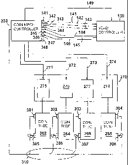
implementation, as shown in FIG. 3, the communication lines
140 connecting the coin mechanism controller 230 and the
vend controller 130 include three coin denomination receipt
lines 141, 142 and 143 for sending signals corresponding,
respectively, to the receipt of acceptable nickels, dimes
and quarters. The communication lines 140 connecting the
vend controller 130 and the coin mechanism controller 230
further include change dispense lines 144, 145 and 146 which
are used as explained below. Each of the change dispense
lines 144-146 corresponds to one of the coin denominations
for which signals can be processed and generated by the vend
controller 130. Thus, for example, the dispense lines 144,
145 and 146 are used to send signals corresponding to U.S.
nickels, dimes and quarters, respectively. The coin
- 10 -
2186051
mechanism controller 230 is designed to connect to the coin
denomination receipt lines 141-143 and the dispense lines
144-146 via ports 341-346, respectively. The coin mechanism
controller 230 can include other ports 347, 348 for
connection to additional coin denomination receipt lines
and/or dispense lines when the system 1 is configured with a
vend controller programmed to handle a larger number of coin
denominations. It should be noted that instead of the three
coin denomination lines 141-143, a single serial
communication line can be used. The coin mechanism
controller 230 would then send a value over the serial
communication line to indicate which denomination coin was
received. Similarly, the three change dispense lines 144-
146 can be replaced by a single serial communication line.
In general, the removable coin mechanism 110 may be
capable of recognizing a set of U.S. coins different from
the set of coins corresponding to the signals which the vend
controller 130 is programmed to process. Thus, for example,
in the following discussion, it is assumed that the coin
mechanism 110 is capable of recognizing and discriminating
between U.S. nickels, dimes, quarters and one-dollar coins.
When the validator 200 determines that an inserted coin 210
is an acceptable nickel, dime or quarter, the coin mechanism
controller 230 sends a signal along the corresponding one of
the lines 141, 142 or 143. Each such signal sent from the
coin mechanism controller 230 to the vend controller 130 can
take the form, for example, of a single pulse. If, on the
other hand, the validator 200 determines that the inserted
coin is an acceptable one-dollar coin, then the controller
230 sends, for example, four pulses along the line 143.
From the perspective of the vend controller 130, the receipt
of a valid one-dollar coin in the coin mechanism is
interpreted as the receipt of four quarters. Of course, the
- 11 -
2186051
coin mechanism controller 230 can be programmed to report
that some other combination of lower denomination coins,
such as ten dimes, or five dimes and ten nickels, was
received. In any event, the vend controller 130 processes
the signals received from the coin mechanism controller 230
to keep track of the total credit available to the customer.
In certain implementations, the vend controller 130 controls
the display 95 so that the total available credit is
displayed to the customer.
Returning to FIG. 2, acceptable coins 210 are
directed to the coin separator 205 by the gate 235. The
coin separator has multiple gates 245, 247, 249 and 251,
also controlled by signals from the controller 230, for
diverting the coin 210 from a main path 250. For better
clarity, the connections between the controller 230 and the
gates 245-251 are not shown in FIG. 2. The coin 210 can be
diverted into respective paths 252, 254, 256 and 258, or the
coin 210 can be allowed to proceed along the path main 250
to a path 260 leading to the cash box 120.
Each of the paths 252, 254, 256 and 258 leads to a
respective one of four coin tubes or containers 262, 264,
266 and 268. Each coin tube 262-268 is arranged to store a
vertical stack of coins of a particular denomination which
can be recognized and accepted by the coin mechanism 110.
Thus, for example, in one implementation, the coin tubes
262, 264, 266 and 268 store U.S. nickels, dimes, quarters
and one-dollar coins, respectively. Although four coin
tubes are shown in FIG. 2, any number can be provided.
A dispenser 270 associated with the coin tubes 262-
268 is operable to dispense coins from the tubes when change
is to be given by the coin mechanism 110. As shown in FIG.
3, the dispenser 270 can include either multiple solenoids
or motors 275, 276, 277 and 278 each of which is associated
- 12 -
CA 02186051 2009-01-08
with a respective one of the coin tubes 262-268 and controls
the dispensing of coins from the respective tube. Suitable
dispensers include those described in U.S. Patent Nos.
3,814,115 and 4,367,760, assigned to the assignee of the
present invention. Each solenoid or motor 275-278
in the dispenser 270 is connected to the coin
mechanism controller 230 by respective dispense
lines 271, 272, 273 and 274. The coin mechanism
controller 230 controls the dispensing of coins
from the tubes 262-268 by sending dispense signals, such as
pulses, along the dispense lines 271-274 to actuate the
solenoids or motors. Dispensed coins are sent to the coin
return 80 where they can be retrieved by the customer.
One or more coin level sensors 301-308 are
associated with each of the coin tubes 262-268. For
example, in the implementation shown in FIG. 3, each coin
tube 262-268 has a pair of coin level sensors. The sensors
301-308 provide signals to the coin mechanism controller 230
via communications lines 310. One sensor from each of the
sensor pairs is used to determine when the coin tubes is
full so that further coins of a particular denomination are
directed to the cash box 120. The other sensor from each
pair of sensors is used to determine when the coin tubes are
empty, or near empty. Other coin level sensor arrangements
and techniques can be used such as those described in U.S.
Patent No. 4,491,140, assigned to the assignee of the
present invention.
The vend controller 130 keeps track of whether
accepted coins are routed to the coin tubes 262-268 or to
the cash box 120. For this purpose, an additional signal
line 149 connects the coin mechanism controller 230 to the
vend controller 130. This signal line 149 is used to
transmit signals to the vend controller 130 to report
- 13 -
2186051
whether an acceptable coin is being routed to one of the
coin tubes 262-268 or to the cash box 120. The vend
controller 130 can also be pre-programmed with the number of
coins which can be stored in coin tubes of particular
denominations, and can keep track of the number of coins of
each denomination that are reported to it as having been
routed to the tubes 262-268.
In general, information reported to the vend
controller 130 regarding the denomination, number and
storage location of coins accepted by the coin mechanism 110
is controlled by the coin mechanism controller 230 by taking
into account the distribution and denominations of coins in
the coin tubes. Since one advantage of the coin mechanism
110 is that it can be used to update existing machines with
an older versions of vend controllers, the coin mechanism
controller 230 is programmed to modify the information
reported to the vend controller 130 under specified
circumstances. Thus, for example, as previously noted, when
the coin mechanism 110 accepts a one-dollar coin, it reports
to the vend controller 130, for example, that four quarters
have been received. This allows the vend controller 130 to
keep track of the total credit available to the customer,
even though the vend controller 130 cannot directly process
signals corresponding to the denomination of the accepted
coin, in this case, a one-dollar coin.
In addition, it is occasionally desirable to route
an accepted coin to an appropriate one of the coin tubes
262-268, but to report to the vend controller that the
accepted coin is being stored in the cash box 120. For
example, a particular vend controller, such as the vend
controller 130, may be pre-programmed to accept five dollar
bills only when a 25-cent coin tube is full so that
sufficient coins will be available for dispensing change.
- 14 -
2186051
The particular vend controller also may be pre-programmed to
assume that the 25-cent tube is full when it receives
information indicating that a quarter has been accepted and
routed to the cash box 120. On the other hand, the desired
amount of change required as a pre-condition for accepting a
five dollar bill actually may be available even if the 25-
cent tube is not full. Such a situation can arise, for
example, due to the availability of one-dollar coins stored
in the tubes 262-268. Thus, in an appropriate situation,
the coin mechanism 110 can receive, accept and route an
inserted quarter to one of the coin tubes 262-268, but
report to the vend controller 130 that a single quarter was
received and routed to the cash box 120. The vend
controller 130 will then assume that the 25-cent coin tube
is full and will allow the bill validator 100 to accept five
dollar bills. Similarly, in appropriate situations, the
coin mechanism controller 230 can route an accepted coin to
the cash box 120, but report to the vend controller that the
accepted coin is being stored in one of the coin tubes 262-
268. The vend controller 130 can take certain actions in
response to a signal indicating that the coin was routed to
one of the coin tubes. For example, the bill validator 100
can be controlled so as to reject bills of a specified
denomination. Specifically, as the amount of change
remaining in the tubes 262-268 decreases, the bill validator
100 can be controlled to accept a one-dollar bill while
rejecting five, ten and twenty dollar bills.
The coin mechanism controller 230 can also be
programmed to report the total number of coins stored in
each coin tube 262-268 after the receipt of a specified
number of coins have been received or after a specified
number of coins of a particular denomination have been
received. Again, the coin mechanism controller 230 can be
- 15 -
218bJ51
programmed to report to the vend controller 130 that a
greater or lesser number of coins have been accepted than
the number of coins that actually have been accepted. Such
intentionally false reporting by the coin mechanism 230 may
be desirable in situations similar to those discussed above
with respect to the intentionally false reporting of the
routing of the coins.
FIG. 4 is a flow chart showing the steps according
to one implementation of the invention. In general, as
indicated by 401, a customer can initiate a transaction by
depositing coins or bills in the slots 50 or 60,
respectively. For example, a particular customer might
deposit a five dollar bill into the slot 60. If the bill
validator 100 recognizes the inserted bill as genuine, it
determines the denomination of the bill, as indicated by
403. The bill is then stored in the stacker 105, and the
bill validator 100 sends a signal along the communication
lines 140 to the vend controller 130 indicating the amount
of acceptable currency received, as indicated by 405 and
407, respectively. As further indicated by 409, the vend
controller 130 keeps track of the total credit available to
the customer, which in this case, is five dollars. As
indicated above, the total available credit can be displayed
on the display 95, as shown in 411. Once sufficient payment
has been deposited in the vending machine 1, the customer
can select a product to be dispensed using the keypad 90, as
shown in 413. As further indicated by 415, the selected
product is then dispensed to a product delivery area (not
shown) where it can be retrieved by the customer.
As indicated by 417, when the available credit
exceeds the price of the selected product, the difference
between the available credit and the price is determined by
the vend controller 130. Thus, if the price of the selected
- 16 -
CA 02186051 2009-01-08
product were $3.50, then using the aforementioned example,
the calculated difference would be $1.50. Next, as shown by
419, the vend controller 130 determines a combination of
coins for paying out the change to the customer. One known
technique, for example, referred to as the "least number of
coins" method, involves using as many higher-denomination
coins as possible, so that the total number of coins is
minimized. Any number of other techniques, however, can be
employed to determine a combination of coins for dispensing
the change, including the technique disclosed in U.S. Patent
No. 5,542,519, assigned to the assignee of the present
invention. In the implementation discussed above,
the vend controller 130 processes and generates
signals corresponding to nickels, dimes and
quarters only. Thus, according to the least number
of coins method, the vend controller 130 would
determine that the best form of paying out change of $1.50
is in the form of six quarters. As indicated by 421, the
vend controller 130 would send six signals, each of which
can take the form of a single pulse, along the dispense line
146. The coin mechanism controller 230 receives and
monitors these pulses, as indicated by 423.
Since, in general, the coin mechanism 110 may be
capable of paying out change using a set of coins different
from the set of coins which the vend controller 130 is
programmed to handle, the best combination of coins for
paying out the change as determined by the vend controller
130 may not, in fact, be the best form of paying out the
change available from the coin tubes 262-268. Therefore, as
shown by 425, the controller 230 recognizes each signal or
pulse received on the dispense lines 144-146 as
corresponding to a predetermined value and determines a
total amount of change, in this case $1.50, corresponding to
- 17 -
2186051
the monitored signals. As indicated by 427, the controller
230 then determines the best combination of available U.S.
nickels, dimes, quarters and one-dollar coins for paying out
the change to the customer. For this purpose, the
controller 230 can be programmed to use the same technique
as the vend controller 130 for determining the best form for
paying out the change. Alternatively, the controller 230
can use a different technique. Using the "least number of
coins method" and, assuming, for example, that nickels,
dimes, quarters and one-dollar coins are available for
paying out change from the tubes 262-268, the controller 230
would determine that the change of $1.50 should be paid out
in the form of a single one-dollar coin and two quarters.
As further indicated by 429, the coin mechanism controller
230 generates signals to actuate the dispenser 270 to
dispense the proper change from the coin tubes 262-268. For
example, the controller 230 would generate a single pulse
which is transmitted along the dispense line 274 and two
pulses which are transmitted along the dispense line 273.
These pulses actuate the solenoids or motors 278 and 277,
respectively, thereby causing a single one-dollar coin and
two quarters to be dispensed from the coin tubes 268 and
266, respectively, as indicated by 431. The dispensed coins
can then be retrieved by the customer, as indicated by 433.
In general, the coin mechanism controller 230
monitors the signals transmitted from the vend controller
130 on the dispense lines 144-146 and acts as an interface
between the vend controller 130 and the dispenser 270.
Specifically, the coin mechanism controller 230 re-
determines the best combination of coins in which to
dispense the change owed to a customer by taking into
account the distribution and denominations of coins in the
coin tubes 262-268. Thus, with reference to the example
- 18 -
2186051
discussed above, the controller 230 causes the coin
mechanism to dispense a single one-dollar coin and two
quarters, rather than six quarters as indicated by the
signals on the dispense lines 144-146.
In different implementations, the coin mechanism
controller 230 can be programmed to use various techniques
to monitor the signals on the dispense lines 144-146 and to
begin paying out the change. According to a first
technique, the coin mechanism 110 accumulates the values
corresponding to the monitored signals on the dispense lines
144-146 until no additional pulse is received during a
specified duration T following the previous pulse. The
specified duration can be, for example, on the order of
milliseconds. Payout does not take place until no further
pulses are received for the specified duration T. According
to a second technique, the values corresponding to the
monitored signals are accumulated, and payout of a single
coin of the highest denomination occurs once the total
accumulated value is at least equal to or higher than the
value of the highest available coin denomination in the
tubes 262-268. Any total accumulated value greater than the
value of the highest denomination coin is accumulated
together with the value of the subsequently monitored
pulses. Payout of the additional change occurs in the same
manner, and a final payout occurs, if necessary, when no
further pulses are received for the specified duration T.
According to yet a third technique, the values corresponding
to the monitored signals are accumulated for a predetermined
number of pulses N, and payout corresponding to the
accumulated value occurs immediately following receipt of
the predetermined number of pulses. Payout of additional
change occurs in the same manner, and a final payout occurs,
- 19 -
2186051
if necessary, when no further pulses are received for the
specified duration T.
The aforementioned payout techniques are illustrated
in FIGS. 5A-5C. For purposes of illustration only, it is
assumed that the vend controller 130 determines that a
customer is owed change totaling $1.65, and, accordingly,
the vend controller 130 generates six pulses on the dispense
line 146 and one pulse on each of the dispense lines 144 and
145, corresponding respectively, to six quarters, one nickel
and one dime. The pulse train received by the coin
mechanism controller 230 is illustrated in FIGS. 5A and 5B,
where, for purposes of illustration only, pulses 1 through 3
and pulses 5 through 7 correspond to quarters, pulse 4
corresponds to a dime, and pulse 8 corresponds to a nickel.
It is further assumed that the time lag between respective
pulses is less than the specified period T, so that the end
of the pulse train is recognized by the controller 230 as
occurring a period T after receipt of pulse 8. In addition,
it is assumed for the purposes of illustration only, that
all the coin tubes 262-268 are full. With respect to the
third technique, illustrated in FIG. 5C, it is assumed that
the predetermined number of pulses N after which payout
occurs is six. In general, the number of pulses N is
variable depending on the number coin tubes and the
different denominations associated with the coin tubes.
Using this example, all three techniques result in the
payout of a single one-dollar coin, two quarters, a dime and
a nickel. The time when payout occurs, however, differs.
According to the first technique, illustrated in
FIG. 5A, there is no payout until a time period T following
receipt of pulse 8. According to the second technique,
illustrated in FIG. 5B, payout of a single one-dollar coin
occurs immediately after receipt of pulse 5, and payout of
- 20 -
CA 02186051 2009-01-08
two quarters, a dime and a nickel occurs after the period T
following receipt of pulse 8. According to the third
technique, illustrated in FIG. 5C, payout of a single one-
dollar coin, a quarter and a dime occurs after receipt of
pulse 6, and payout of another quarter and a nickel occurs
after the period T following receipt of pulse 8.
As indicated above, the coin mechanism controller
230 is programmed to take account of the distribution and
denominations of coins in the coin tubes 262-268. Thus, for
example, if the one-dollar coin tube 268 is empty, there is
no need for the controller 230 to re-calculate the best form
of paying out the change, because the coin types currently
available as change from the coin mechanism 110 correspond
to the coin types for which the vend controller 130
generates signals on the dispense lines 144-146. Using the
example discussed above with respect to FIGS. 5A-5C, the
controller 230 would generate six pulses which are
transmitted along the dispense line 273, one pulse which is
transmitted on the dispense line 272, and one pulse which is
transmitted along the dispense line 271. The dispenser 270
would then dispense six quarters, one dime and one nickel.
In a further aspect of the invention illustrated in
FIG. 6, the coin tubes 262-268 can be part of a removable
and replaceable cassette 501. One such suitable cassette is
described in U.S. Patent No. 5,400,891, assigned to the
assignee of the present invention. The feature
of a removable and replaceable cassette permits
various cassettes, each of which can differ
according to the distribution of denominations
associated with the coin tubes 262-268, to be
used in conjunction with the coin mechanism 110 and the
vending machine 1. As before, the coin mechanism controller
230 serves as an interface between the vend controller 130
- 21 -
2186051
and the coin mechanism 110. To identify the arrangement of
the coin tubes in a particular cassette to the coin
mechanism controller 230, the coin mechanism 110 includes a
keypad 503 with multiple buttons 505, which are electrically
connected to the coin mechanism controller 230. The keypad
503 can be used, among other things, to enter a code, such
as a four-letter or four-digit code, that identifies the
arrangement of the coin tubes to the coin mechanism
controller 230. The code may also be a-combination or a
particular sequence of letters and numbers that can be
suitably entered using the keypad 503. The coin mechanism
controller 230 is programmed to recognize the code, and, in
response to the code, to operate and control the gates 245-
251 in FIG. 2 to divert an accepted coin to a proper one of
the tubes 262-268 or to the cash box 120. Once the coin
mechanism controller 230 is provided with the information
concerning the identity of the coin tube arrangement, the
controller 230 can re-calculate the best combination of
coins in which to dispense the change owed to a customer by
taking into account the denominations as well as the
distribution of coins in the coin tubes of the particular
cassette.
FIG. 7 shows a cassette 601 which includes four coin
tubes 602 - 605, and which can replace the cassette 501 in
FIG. 6. For the purposes of illustration, it is assumed
that the coin tubes 602, 605 are arranged to store vertical
stacks of nickels and the coin tubes 603, 604 are arranged
to store stacks of dimes. Of course, other cassettes having
different tube arrangements can also be used with the
invention. For example, a cassette having four tubes each
of which stores coins of the same denomination can be used.
Alternatively, two tubes can store coins of a first
denomination, while the remaining two tubes store coins of
- 22 -
2186051
second and third denominations, respectively. In any event,
when the cassette 601 is inserted into the coin mechanism
110 by service personnel, the service personnel enters a
predetermined code using the keypad 503. The code
corresponds to the particular arrangement of coin tubes in
the cassette 601. The coin mechanism controller 230
receives and recognizes the code.
Again, for purposes of illustration, it is assumed
that the vend controller 130 determines that a customer is
owed change totaling $0.50 and generates two pulses on the
dispense line 146 corresponding to two quarters. It is also
assumed that the coin mechanism controller 230 is programmed
to monitor the signals on the dispense lines 144-146
according to the second technique in which the values
corresponding to the monitored signals are accumulated, and
payout of a single coin of the highest available
denomination occurs once the total accumulated value is at
least equal to or higher than the value of the highest
available coin in the tubes 602-605. Any total accumulated
value greater than the value of the highest denomination
coin is accumulated together with the value of the
subsequently monitored pulses. Payout of the additional
change occurs in the same manner, and a final payout occurs,
if necessary, once no further pulses are received for the
specified duration T. In this example, two dimes would be
dispensed immediately after receipt of the first pulse on
the dispense line 146, and three dimes would be paid out
immediately after receipt of the second pulse on the
dispense line 146.
In various implementations, the invention provides
one or more of the following advantages. Since the coin
mechanism controller 230 serves as an interface between the
vend controller 130 of the vending machine 1 and other
- 23 -
2186051
components in the coin mechanism 110, the coin mechanism 110
can be used to update existing vending machines without
replacing the vend controller. For example, an existing
vending machine 110 can be upgraded to accommodate new or
different combinations of coin sets by replacing an existing
coin mechanism with the coin mechanism of the invention. In
particular, an existing vending machine can be upgraded
relatively easily to accept payment and dispense change in
the form of new or different combinations of coin
denominations. For example, by using the coin mechanism of
the invention, a vending machine can be updated to dispense
a one-dollar coin even though the existing vend controller
generates signals indicating that four quarters should be
dispensed. The coin mechanism 110 is sufficiently flexible
and adaptable that it also can be used with vending machines
whose vend controller has already been updated to
accommodate new or different combinations of coin
denominations. Furthermore, removable and replaceable
cassettes with different arrangements of coin tubes can be
used with a single coin mechanism. The use of a keypad
allows service personnel to enter a code which is
transmitted to the coin mechanism controller and provides a
convenient means for identifying the coin tube arrangement
in the cassette to the coin mechanism controller. The coin
mechanism of the invention can, therefore, provide enhariced
flexibility and adaptability to existing machines with
relative ease and at relatively low cost.
Although the invention has been described with
respect to vending machines, the coin mechanism of the
invention can be used in any apparatus, such as a gaming
machine which accepts payment and/or dispenses change in the
form of coins. The invention can also be used in connection
with semi-automatic transaction systems, such as cash
- 24 -
2186051
registers. Similarly, although the invention has been
described with respect to machines that dispense coins as
change, the invention can also be used in a machine which
dispenses coins as a prize to the customer.
Other implementations are contemplated within the
scope of the following claims.
- 25 -