Note: Descriptions are shown in the official language in which they were submitted.
2186199
This application is a Continuation-in-Part of U.S. Patent
~ Application Serial No. 08/222,579, filed April 4, 1994, in the
name of Yan Razdolsky.
TITLE OF THE INVENTION
A METHOD OF MANDIBULAR DISTRACTION OSTEOGENESIS
~ ~POUND OF THE INVENTION
The present invention relates generally to the correction of
deficiencies in mandibular growth. More specifically, the
present invention relates to a method mandibular distraction
osteogenesis the (lengthening of the lower jaw by stretching) for
correcting deficiencies in mandibular length.
Deficiencies in mandibular growth which lead to
characteristic protrusions of the maxillary teeth and
deficiencies of the chin are quite common in American and
Northern European populations. Data from recent large scale U.S.
Public Health Service surveys of the occlusion of children and
youth ages 6 through 10 indicate that about 20 percent of the
U.S. population has mandibular deficiency, and about 5 percent of
the total U.S. population has skeletal mandibular deficiency
(deficiency in the growth of the lower jaw) so severe that the
only way to correct such deficiency is to perform a total
mandibular (lower jaw) resection (osteotomy) and to advance the
lower jaw to a more favorable forward position.
A total mandibular osteotomy, or a sagittal split osteotomy,
~18~1 99
is a major surgical procedure that can have many complications.
In this procedure, as illustrated in Fig. 1, a human mandible is
split at opposite points on the mandible. The forward part of
the mandible is then brought apart from the rearward part and
stabilized with either: (1) screws at point S as labeled in the
figure (the forward part F is indicated in Fig. 1 by the arrows A
as having been moved; this procedure is used less commonly now
than in previous years due to the inherent difficulty in
positioning of three loose parts of the mandible correctly during
the surgery) or (2) splinting of the broken lower jaw to a
prefabricated interocclusal splint which is secured to the upper
jaw and allowing it to heal for approximately 2 months (during
which the patient cannot open his/her mouth, cannot communicate
or function and is fed through a straw).
This procedure cuts the bone marrow, and thus could be
detrimental to the inner nerves and blood vessels of the
mandible.
In addition, a total mandibular osteotomy can involve the
complications of bleeding, obstruction of the airway, possible
infection, neurological problems such as possible paralysis of
the inferior alveolar nerve and loss of sensation to the lip,
failure of intermaxillary fixation (stabilization of the mandible
21861~9
- after surgery), relapse-movement of the lower jaw in the
direction from which it was advanced, and possible displacement
of the temporo-mandibular jaw joints during the surgery.
Needless to say, such surgery requires a hospital stay, is
very expensive and many patients are reluctant to agree to this.
Further, total treatment time is on the order of 30 months.
The other 15 percent of mandibular deficiencies are less
severe, and if they are caught early, during the pubertal growth
stage, are amenable to conventional orthodontics (braces) or a
combination of orthodontics and functional appliance treatment.
However, functional appliances are of most benefit to a patient
when the patient is undergoing body and jaw growth, and cannot
benefit adult (non-growing) patients.
One other prior art surgical technique bears mention. A
process of lengthening human long bones (limbs, arms, etc.) by
distraction osteogenesis has been utilized for the past 40 years.
This process was designed by a Russian surgeon, Dr. Gavriel A.
Ilizarov. The principles of the method of Dr. Ilizarov are
presented in an article based on a speech delivered by Dr.
Ilizarov on October 30, 1987 at the annual Scientific Program of
the Alumni Association and material presented by Dr. Ilizarov at
218619~
- a three day international conference on the Ilizarov techniques
for the management of difficult skeletal problems. His technique
is being widely used by orthopedic surgeons throughout the United
States and the world.
SUMMARY OF THE INVENTION
The object of the present invention is to a method of
mandibular distraction osteogenesis that is applicable to the
five percent of severe cases requiring surgery as well as to the
less severe 15 percent of cases if those cases have missed their
opportunity for orthodontic/functional correction during their
pubertal growth years. Distraction osteogenesis is, by
definition, the process of generating new bone by stretching.
Thus, it is the more specific object of the present invention to
provide a process using a device for generating new mandibular
bone by stretching the mandible, while orthodontically
lengthening the mandible and minimizing the extent of the
conjunctive lower jaw surgery.
The objects of the present invention are met by a method
using an intraoral appliance or device in mandibular distraction
osteogenesis. This method involves performing corticotomy
surgery, where only the cortex of the mandible is cut, leaving
all bone marrow, nerve and blood vessels intact, at two points on
21861q9
opposite sides of the mandible. The intraoral device is an
expandable distraction device attached to the teeth of the
mandible on opposite sides of the two points of the corticotomy
surgery, and the expandable distraction device is then
periodically expanded until a desired mandibular length is
attained.
The method further comprises preparing the expandable
distraction device for attachment during the corticotomy surgery.
This includes fitting a plurality of stainless steel crowns onto
the teeth of the mandible, taking an impression of the teeth of
the mandible, removing the crowns from the teeth of the mandible
and placing the crowns in the impression, preparing a solid model
of the teeth of the mandible from the impression, the crowns
being located on the solid model, and then attaching the
expansion screw devices to the crowns.
Preferably, two expansion screw devices and two sliding tube
devices are attached to eight crowns fitted onto the teeth of the
mandible in the step of fitting, including two bicuspid and two
molar crowns on each side of the mandible.
The impression is preferably a rubber base impression that
is poured up with dental stone or plaster. The expansion screw
2186199
devices and sliding tube devices are preferably soldered to the
crowns by means of sliding (removable) attachments, in a very
precise three dimensional location.
The expandable distraction device is subsequently expanded
in the desired direction of the distraction of the mandible. The
screw devices separate the crowns on each side of the mandible
from each other at the point of the corticotomy surgery on the
mandible. Preferably, the expandable screw devices are expanded
at a rate of lmm per day, starting the day of the surgery.
Through the employment of mandibular distraction
osteogenesis according to the present invention with the use of
the intraoral mandibular distraction device according to the
present invention, a number of significant advantages may be
achieved. As noted above, the invention will orthodontically
lengthen the mandible while minimizing the extent of the
conjunctive lower jaw surgery. Only corticotomy is employed.
Further, the invention will improve the facial profile by
advancing or lengthening the deficient mandible. This will
improve the lip balance, lip competence, and lip seal. This will
also help to eliminate mouth breathing pattern problems.
Further, incisor guidance and function will be established.
-- 2~6199
The invention will also reduce the orthodontic-surgical
treatment time. Treatment time can be expected to be reduced to
on the order of 12 months, instead of 30 months as with the prior
art sagittal split osteotomy surgery.
The invention will also bring the mandible forward, thus
bringing the tongue forward and diminishing chances for
obstructive sleep apnea or snoring. Such correction will also
help to prevent class II mandibular deficiency/malocclusion. The
invention will help to correct unilateral cross bites and the
mandibular midline.
Further, the invention will minimize damage to the
periosteal and endosteal blood supply by performing a corticotomy
only, rather than a complete osteotomy as is now performed with
the sagittal split osteotomy surgery. This will minimize
swelling and post-surgical complications, and requires no
hospital stay and could be done on an outpatient basis.
Furthermore, the fact that the expansion screw assemblies are
detachable from the receptor assemblies means that the
orthodontist will generally not need to be present during
surgery. The precise pre-alignment will have been done during
fitting in the office.
-- 2186199
- Further, the procedure will be far less expensive than the
conventional mandibular osteotomy surgery. Patient costs for the
procedure are lower than the costs associated with prior art
methods such as the sagittal split osteotomy surgery. Obviously
this will tend to lower health care costs in general, which is a
great concern at this time.
Other significant advantages result to the benefit of the
patient. The procedure according to the present invention
results in less pain to the patient than the prior art procedure.
The recovery period after completion of the procedure is on the
order of two to three days, rather than two months as with other
methods. The jaw of the patient does not have to be wired shut
for two months, and the patient is able to return to work within
one week, as opposed to eight weeks with other methods. Thus it
is clear that the psychological impact of the procedure on the
patient will be significantly reduced as compared with the impact
of the prior art methods.
BRIEF DESCRIPTION OF THE DR~WINGS
The present invention will be described in detail below with
reference to the accompanying drawings, in which:
Fig. 1 is a schematic drawing illustrating sagittal split
2 ~1 86 1 99
osteotomy surgery;
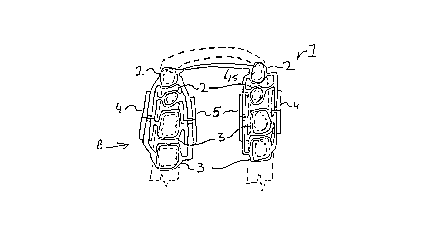
Fig. 2 is a top view of a mandibular distraction
osteogenesis device according to the present invention;
Fig. 3 is a side view of a portion of the mandibular
distraction device as seen in the direction of arrow B of Fig. 2;
Fig. 4 is a schematic representation of corticotomy surgery;
Fig. 5 is a partial perspective view of a Razdolsky
attachment plug according to a first embodiment of attachments
for the mandibular distraction device according to the present
invention;
Fig. 6 is a perspective view of a receptor according to the
first embodiment of the Razdolsky attachments, the receptor being
mounted on a crown;
Fig. 7 is an exploded view of the plug and a screw device
according to the first embodiment of the Razdolsky attachments;
Fig. 8 is an exploded view of a screw device, a cap and a
receptor according to a second embodiment of the Razdolsky
218619~
- attachments according to the present invention;
Fig. 9 is a perspective view of a cap and a receptor
according to a third embodiment of the Razdolsky attachments of
the present invention;
Fig. 10 is a perspective view of the cap of Fig. 9;
Fig. 11 is a perspective view from the rear of the receptor
of Fig. 9;
Fig. 12 is a perspective view of a receptor according to a
modification of the third embodiment of the Razdolsky
attachments;
Fig. 13 is a perspective view of a cap suitable for use with
the receptor of Fig. 12;
Fig. 14 is a perspective view of a screw device, cap and
receptor according to a fourth embodiment of the Razdolsky
attachments of the present invention;
Fig. 15 is a perspective view of the cap of Fig. 14;
2 1 ~ 1 9~
Fig. 16 is a perspective view of the receptor of Fig. 14;
Fig. 17 is a schematic view of a receptor according to the
fourth embodiment of the Razdolsky attachments used together with
the receptor according to a fifth embodiment of the Razdolsky
attachments of the present invention;
Fig. 18A is a perspective view of the receptor according to
the fifth embodiment of the Razdolsky attachments;
Fig. 18B is a perspective view of a screw device, cap and
receptor according to the fifth embodiment; and
Figs. l9A-19D are illustrations of steps in the process of
using the present invention.
DETAT~.~n DESCRIPTION OF THB PREFERRED
EMBODIMENT OF THE l~.V~..lON
A detailed description of the present invention will now be
presented with reference to the accompanying drawing figures. In
the various figures, the same reference numerals are used for
similar elements throughout. The description of the invention
will proceed with the description of a mandibular distraction
osteogenesis device, and in particular Razdolsky attachments for
~ 1 8/~ 1 ~9
the purpose of securing expansion screws and sliding tubes onto
the stainless steel crowns in a precise angular fashion and
making both expansion screws and sliding tubes removable prior to
corticotomy surgery, and the method of mandibular distraction
osteogenesis.
Turning to Fig. 2, there is illustrated a mandibular
distraction osteogenesis device 1 usable in distracting the
mandible. Initially, the device 1 includes a plurality of crowns
(or bands, collectively also referenced as tooth engagement
members) for placement on the teeth of the mandible of a patient
that is to undergo distraction osteogenesis. The tooth
engagement members of the present invention are preferably
crowns, but it should be recognized that bands could also be
employed instead of crowns; the description will primarily
discuss crowns. In Figs. 2 and 3, while the description
references crowns, the illustration in these figures is not meant
to be indicative of any particular type of crown but to be simply
a generic description of a crown or band for purposes of
illustrations.
Preferably there are provided a total of eight crowns, with
two bicuspid and two molar orthodontic crowns being provided for
each side of the mandible, as illustrated in Fig. 2. The crowns
2~1 99
are indicated by reference numbers 2 for the bicuspid crowns and
reference numbers 3 for the molar crowns. The mandible and the
relevant teeth are schematically illustrated by a dashed line in
Fig. 2.
One universal expansion screw 4 is soldered onto each buccal
(cheek) side of the crowns and one universal sliding tube device
5 is soldered onto each lingual (tongue) side of the crowns for
each side of the mandible. One universal expansion screw 4 and
one sliding tube 5 is thus placed on each side of each set of
crowns. As can be seen from Fig. 2, the universal expansion
screws thus extend along the sides of the crowns and have
suitable portions thereof soldered to the respective crowns. The
universal expansion screws 4 are expandable to distract a forward
portion of the mandible, the upper portion as seen in Fig. 2,
from a rearward portion of the mandible by separating the
bicuspid bands 2 from the molar bands 3.
More specifically, and referring to Fig. 3, each universal
expansion screw 4 has two halves 6 and 7 separable from each
other by a screw mechanism 8. The screw mechanism 8 is a
suitable mechanism rotatable between the universal expansion
screw halves 6 and 7 to separate the halves from each other, such
as a right and left hand threaded shaft extending into and
13
;~18~1q~
engaging with corresponding threads in the halves 6 and 7.
Suitable guide rods g can also extend through the halves 6 and 7
to guide the separation of the halves 6 and 7 from each other.
As can be seen, suitable connecting portions are provided for
connecting the halves 6 and 7 to the respective bands 2 and 3.
Such connecting portions can take the form of appropriate metal
wires or bars. The universal expansion screw 4 can be of the
type illustrated in U.S. Patent 4,482,318, for example, or could
be of the type shown in U.S. Patent 4,571,177, suitably adapted
to the present situation. These patents are incorporated herein
by reference.
By the above construction there is formed two separate
portions of the mandibular distraction device 1, one portion
being located on each side of the mandible. These portions are
preferably connected to each other by a suitable connecting wire
or bar 15, as illustrated in Fig. 2. However, note that in place
of the connecting wire or bar 15, an additional, smaller,
universal expansion screw 4 could be provided and incorporated
into the device 1, the universal expansion screw connecting the
two sides of the device 1 at the forward portions thereof in
order to allow for lateral mandibular expansion, in addition to
mandibular distraction or elongation.
218~
As can be seen from Fig. 2, the bicuspid crowns 2 on each
side of the mandible are connected to the forward portions or
halves 6 of the universal expansion screws 4, and the molar
crowns 3 are connected to the rear portions or halves 7 of the
universal expansion screws 4. Thus, a unitary forward portion is
expansible in a forward direction relative to two separate
lateral portions on opposite sides of the mandible for elongation
or distraction of the mandible.
Though not specifically illustrated, the sliding tubes 5
represent simple expandable sliding tube and pin connections
connecting the forward and rearward portions of the device 1 on
each side of the mandible. These tube and pin connections have a
simple tube receiving a pin with the tube connected to one
portion and the pin connected to the other portion and extending
in the same direction as the expansion screws 4. Thus these
devices will simply follow the distraction of the mandible along
with the activation of the screw devices 4, but will provide for
support on the lingual side of the crowns in all directions
except for the direction of expansion. Such sliding tubes, as
well as the expansion screws and crowns, are separately readily
available from orthodontic suppliers.
While the above described distraction device 1 simply
~3il861 9~
solders the expansion screws and sliding tubes 5 to the crowns 2
and 3, it is preferred that specific attachments be employed for
this purpose, as will be described below. These attachments,
generally referred to as Razdolsky attachments, comprise receptor
attachments attached to the respective crowns, preferably by
soldering, and connector attachments connected to the respective
screw devices and sliding tubes 5 also by soldering. The
receptors and connectors are thus removably engageable with each
other so that they screw devices 4 and sliding tubes 5 can be
lo removably attached to the crowns, for reasons as will be
discussed below in describing the method of mandibular
distraction osteogenesis in accordance with the device of the
present invention. At this point, specific description of the
Razdolsky attachments will be made.
A first embodiment of the Razdolsky attachments is
illustrated in Figs. 5-7. Fig. 5 illustrates a plug attachment
for attachment to a screw device 4, Fig. 6 illustrates a crown 2
or 3 having a connector 25 connected therewith and Fig. 7
illustrates a connection between the screw device 4 and the plug
20.
The attachment plug 20 according to the Razdolsky
attachments comprises a front portion 21 having a front surface
21~1 qq
and a plug portion 22. The plug portion 22 tapers from its
distal end in the Z direction to the front portion 21, as
illustrated.
Fig. 6 illustrates a stainless steel crown 2 or 3,
preferably a stainless deep drawn thin shell molar or bicuspid
cap as are commercially available. The receptor 25 is soldered
to the stainless steel cap, and is preferably itself an
investment cast stainless steel, etc. Solder flow details are
provided on each side as illustrated at 26, noting the beads on
the vertical sides of the receptor 25. The majority of the
receptor 25 comprises the back portion soldered to the cap. A
slot 27 is formed by a front portion 29, which has outwardly
jutting walls defining the slot 27 as a slot tapering from the
back portion toward the front. The slot is opened at its top and
forward sides, and is closed at the back and lower portions
thereof. The lower portion at 28 forms a vertical stop.
As seen in Fig. 7, expansion device solder legs 24 of the
screw device 4 can be soldered to the front portion 21 of the
plug 20 as noted at 23, designating a solder surface on the plug
20. During assembly, the plug 20 can then have its plug portion
22 vertically inserted into the slot 27 of the receptor 2S, the
plug 22 being complementary to the slot 27 for a snug fit. The
- 21861~
plug 22 can be a solder plug and can provide a snug fit with a
very low viscosity adhesive joint in the receptor 25.
The receptor 25 has a height h and a radius of its back
surface R. The receptor 25 can thus be provided in several
general ranges of sizes for general ranges of the sizes of teeth.
A second embodiment of the Razdolsky attachments is
illustrated by Fig. 8. In this figure, the attachments comprise
a cover or cap 30 in place of the plug, and a receptor 35. The
receptor 35 is illustrated as attached to a molar crown 3, for
example by soldering. The receptor 35 has a front portion 38
having lateral flanges with respect to the back portion 37 that
is connected to the crown 3. The flanges have a slight taper
shown at 36. The cap or cover 30 has flanges or channel members
31 forming channels for engagement with the flanges of the front
portion 38. When engaged as illustrated, the slight taper wedges
the cap or cover 30 in place, and the cap 30 engages a vertical
stop 39 on the bottom of the receptor 35.
Figs. 9-11 illustrate a third embodiment according to the
Razdolsky attachments of the present invention. In this
embodiment, the cap 40 engages a receptor 45. The receptor 45
has a vertical stop 46 similar to the above embodiments, and an
18
218619~
alignment hole 47. The cap 40 has channels 42 for engaging the
rear surface of the receptor 45, with the turned flanges of the
channels 42 having a taper at 41. The taper is provided for a
tight fit against triangular engagement members 48 on the
receptor 45, which are similarly tapered. According to a
particular feature of this embodiment, glue pockets 49 are
provided on the back surface of the receptor 45 for gluing the
cap 40 to the receptor 45 during surgery.
In a variation of the third embodiment illustrated in Fig
12, bendable wings 48b can be soldered at 48a to the rear
engagement portions 48 of the receptor 45. These bendable wings
can engage a molar cap 3.
Fig. 13 provides a front perspective view of the cap 40
according to the third embodiment of the Razdolsky attachments of
the present invention.
Figs. 14-16 describe a fourth embodiment of the Razdolsky
attachments according to the present invention. A cap 50 is
similar to the cap discussed with respect to the third embodiment
of the Razdolsky attachments and is connected to the screw device
4 in a similar manner. However, in this embodiment a slot 51 is
provided in the cap for receipt of a pry bar for removal of the
` 21~199
cap from the receptor during an intermediate step of the
procedure. It will be recognized that the slot could be provided
with the other embodiments of the connectors of the present
invention. A receptor 55 of this embodiment is similar to the
receptor of the third embodiment of the Razdolsky attachments in
that it has a similar front portion providing a vertical stop and
an alignment hole 57, and provides similar glue pockets at the
rear surface of the front portion. However, with this embodiment
the rear portion is extended further back and connected with two
laterally extending tabs 56 so that the single receptor 55 may be
connected with two molar caps 3 as illustrated in Fig. 14. As
seen at 58, the tabs 56 are soldered to the stainless steel caps.
Thus employment of this embodiment will reduce the number of
receptors and caps necessary for connection of the expansion
screw devices 4 and sliding tube devices 5 on the sides of the
lines of crowns. This will be further discussed below.
Figs. 17-18B illustrate a fifth embodiment of the Razdolsky
attachments according to the present invention, and can be used
together with the fourth embodiment. That is, in this embodiment
a receptor 65 has a front portion 67 with a vertical stop 66
similar to that of the third and fourth embodiments. However,
instead of having the laterally extending tabs of the fourth
embodiment, an intermediate portion 68 extends rearwardly from
- 2 1 861 ~q
one side of the rear surface of the front portion 67, and
continues into a back portion 69 that extends from the
intermediate portion 68 at an angle that is acute relative to the
direction of the expander assemblies. The cover 60 is similar to
the previous embodiments and is provided with a pry slot 61 for
engagement by a suitable tool, such as a thin bladed screwdriver,
etc. As illustrated in Fig. 18B, the back portion 69 is soldered
at 65a to two bicuspid crowns 2. The angle of the portion 69
allows the front 67 to be better aligned with respect to the
assembly of the screw device 4 with its respective caps soldered
thereto. In this regard, note Fig. 17. In this figure, two
bicuspid caps are seen as connected with the receptor 65 and two
molar caps are seen as connected with the receptor 55 according
to the fourth embodiment. As seen in the figure, by the angled
rear portion 69 of the receptor 65, both the front portions of
the respective receptors can be aligned with reach other, making
the process of assembly a simple matter.
With respect to the fifth embodiment, the bicuspid receptor
65 that is illustrated in Fig. 18A is obviously only usable on
one side of the distraction device, i.e. on one side of the
mandible. However, it is contemplated that a symmetric bicuspid
receptor could be manufactured that would be usable on both sides
of the mandible so that only one part would have to be
- ~18~1~9
manufactured.
The method of mandibular distraction osteogenesis according
to the present invention is as follows. Referring to Figs. 2-4,
first two bicuspid and two molar orthodontic crowns are fitted
onto the respective teeth of a patient's mandible on each side of
the mandible. Thus, a total of eight crowns are fitted onto the
teeth of the patient. A rubber base impression is then taken of
the patient's mandible with the crowns in place. The crowns are
then removed and placed into the impression. Then, the
impression is poured up with orthodontic (dental) stone or
plaster, so as to form a model of the patient's mandible, with
the crowns in place thereon on the appropriate teeth of the
mandible model.
The two universal expansion screws 4 are then soldered onto
the connectors of the Razdolsky attachments and the receptors are
soldered onto the crowns (Fig. l9A) in a very precise angular
fashion preferably using the laboratory instrument discussed in
U.S patent application Serial No. 08/222,579, filed April 4, 1994
(incorporated herein by reference). Two sliding tubes are also
soldered onto the crowns 2 and 3 in a simple fashion utilizing
the Razdolsky attachments. Thus the mandibular distraction
device 1 is formed. A suitable connection 15 (Fig. 2, which
2 1 861 99
shows the embodiment not using the attachments) may also be
provided, or an additional universal expansion screw 4 may also
be provided in place thereof to provide for lateral mandibular
expansion. With the finished mandibular distraction device 1,
the device is now ready to be cemented into the patient's mouth.
Accordingly, the mandibular distraction device is cemented
into the patient's mouth prior to corticotomy surgery as at 70
(Fig. l9B). All expansion screws and sliding tubes are then
removed (Fig. l9C) by means of the Razdolsky attachments, which
guarantee the previous exact angular positioning, and are only to
be reinserted after the corticotomy surgery is performed. When
the screw devices and sliding tubes are removed by the use of the
Razdolsky attachments, the crowns stay cemented on the patient's
teeth. This technique provides for maximum access and visibility
during the surgery. Corticotomy surgery is then performed, which
is the cutting of the outside layer (cortex) only of the mandible
(Fig. 19D). Referring to Fig. 4, a section of the patient's
mandible is schematically illustrated. Portion 10 represents the
outer layer of the bone, i.e. the cortex. This portion is cut
during the corticotomy surgery. However the bone marrow 11 is
left intact. This reduces the chance of the nerves or the blood
vessels being severed. The location of the corticotomy surgery
is represented in Fig. 4 by the letters CS. The corticotomy
2186199
surgery is performed at two points on opposite sides of the
mandible to allow for the elongation or distraction of the
forward portion of the mandible from the rearward portion
thereof. The corticotomy preferably takes place posterior to the
lower second bicuspids, and preferably between the bicuspids and
the molars on each side of the mandible to allow for the two
bicuspid crowns 2 on each side to be displaced forwardly from the
rear molar crowns 3 with the expansion of the universal expansion
screws 4. Appropriate x-rays can be taken of the mandible in
order to determine the exact thickness of the cortex to ensure
that the bone marrow 11 is not cut.
After the reinsertion of the expansion screws and sliding
tubes after corticotomy surgery, the mandible is then distracted
by expanding the two universal expansion screws 4 inside of the
patient's mouth. This is accomplished by rotating the screws 8
of the universal expansion screws 4 periodically to extend the
forward portion of the mandible from the rearward portion
thereof. This is possible because the cortex has been cut in the
corticotomy surgery. The bone marrow is softer tissue and allows
for elongation to take place. Both bone and soft tissue
regeneration will occur during the process of expanding the
universal eYp~nsion screws 4 and distracting the mandible.
Preferably, the mandible is distracted at a rate of lmm per day
24
- 2~1 361 99
until the proper mandibular length is obtained. There may be
differential eYp~nsion between the left and right sides in order
to maintain expansion along the centerline of the mandible.
Note that when reinserting the expansion screws and sliding
tubes, the respective connectors are connected with the
respective receptors. At this time, the receptors and connectors
are preferably permanently bonded to each other prior to
adjustment of the mandible by a suitable adhesive. However, as
an alternative to adhesive, it is contemplated that a locking
mechanism could be provided between each connector and receptor.
Such a locking mechanism would preferaby be of a type in which
the receptor and connector are securely fixed with each other,
but which could be quickly released by the orthodontist or
surgeon, and different types of such locking mechanisms will
occur to those of skill in the art.
While preferred embodiments of the present invention have
been described above in some particularity, the scope of the
present invention should not be limited thereby, as various
modifications thereof will be apparent to those of skill in the
art.