Language selection

Search

Patent 2186346 Summary

Third-party information liability

Some of the information on this Web page has been provided by external sources. The Government of Canada is not responsible for the accuracy, reliability or currency of the information supplied by external sources. Users wishing to rely upon this information should consult directly with the source of the information. Content provided by external sources is not subject to official languages, privacy and accessibility requirements.

Claims and Abstract availability

Any discrepancies in the text and image of the Claims and Abstract are due to differing posting times. Text of the Claims and Abstract are posted:

  • At the time the application is open to public inspection;
  • At the time of issue of the patent (grant).
(12) Patent Application: (11) CA 2186346
(54) English Title: CATALYTIC METHOD
(54) French Title: PROCEDE CATALYTIQUE
Status: Deemed Abandoned and Beyond the Period of Reinstatement - Pending Response to Notice of Disregarded Communication
Bibliographic Data
(51) International Patent Classification (IPC):
  • F01N 03/20 (2006.01)
  • F01N 01/00 (2006.01)
  • F01N 01/08 (2006.01)
  • F01N 03/26 (2006.01)
  • F01N 03/28 (2006.01)
  • F01N 03/30 (2006.01)
  • F01N 03/34 (2006.01)
(72) Inventors :
  • PFEFFERLE, WILLIAM C. (United States of America)
(73) Owners :
  • WILLIAM C. PFEFFERLE
(71) Applicants :
  • WILLIAM C. PFEFFERLE (United States of America)
(74) Agent: SMART & BIGGAR LP
(74) Associate agent:
(45) Issued:
(86) PCT Filing Date: 1995-12-21
(87) Open to Public Inspection: 1996-08-01
Availability of licence: N/A
Dedicated to the Public: N/A
(25) Language of filing: English

Patent Cooperation Treaty (PCT): Yes
(86) PCT Filing Number: PCT/US1995/016836
(87) International Publication Number: US1995016836
(85) National Entry: 1996-09-24

(30) Application Priority Data:
Application No. Country/Territory Date
08/377,861 (United States of America) 1995-01-25

Abstracts

English Abstract


An emissions control system for rich-burn internal combustion engines, includes a reaction chamber (7) for thermal oxidation of
exhaust gas fuel values. A passive means (5, 4) utilizes exhaust flow energy (2) for induction of air into engine exhaust gas, and a duct
(3) transfers the exhaust gas together with the inducted air into the reaction chamber (7) for thermal oxidation. To achieve a high degree
of efficiency the thermal oxidation is facilitated by thorough mixing of air and exhaust gas by recirculation means (9) to insure gas phase
thermal reaction.


French Abstract

Cette invention se rapporte à un système de contrôle d'émissions, qui est destiné à des moteurs à combustion interne à mélange riche et qui comprend une chambre de réaction (7) servant à l'oxydation thermique des valeurs combustibles des gaz d'échappement. Un moyen passif (5, 4) utilise l'énergie (2) de l'écoulement des gaz d'échappement pour obtenir une induction d'air dans des gaz d'échappement du moteur, et un conduit (3) transfère dans la chambre de réaction (7) des gaz d'échappement avec l'air induit, en vue de leur oxydation thermique. Pour atteindre un degré élevé d'efficacité, on facilite l'oxydation thermique en mélangeant à fond l'air et les gaz d'échappement à l'aide d'un moyen de remise en circulation (9), assurant ainsi une réaction thermique de la phase gazeuse.

Claims

Note: Claims are shown in the official language in which they were submitted.

11
WHAT IS CLAIMED IS:
1. An emissions control system for a rich-
burn, small internal combustion engine, which
comprises;
a. a small internal combustion engine
having mounted on the exhaust thereof an engine
noise muffler;
b. a reaction chamber within the engine
exhaust muffler for thermal oxidation of fuel values
in the engine exhaust;
c. means within the reaction chamber for
inducing effective recirculation of the exhaust
flowing through said reaction chamber, and creating
a low pressure region in the reaction chamber
proximal the chamber inlet;
d. passive means to utilize exhaust flow
energy as the sole means for induction of air into
the engine exhaust; and
e. duct means for transfer of said
exhaust together with said inducted air into said
reaction chamber.
2. The system of claim 1 wherein the engine
has a displacement of less than about 800 cc.

12
3. The system of claim 1 wherein the engine
is a single cylinder engine.
4. The system of claim 1 wherein at least a
portion of the internal walls of said reaction
chamber comprise a catalyst to stabilize thermal
combustion.
5. The system of claim 4 in which the
catalyst comprises a platinum group metal.
6. The system of claim 1 wherein the air
inlet of said passive air induction means is encased
in a shroud to muffle exhaust pulse noise.
7. The system of claim 1 wherein said passive
air induction means is a flow jet injector.
8. The method of controlling carbon monoxide
and hydrocarbon emissions from a rich-burn small
internal combustion engines comprising the steps of:
a. passing the exhaust gas pulses through a
nozzle to provide a gas jet;
b. passing said jet into the open end of a
flow duct thereby inducting air into said duct with
said exhaust gas; and

13
c. mixing the inducted air and the exhaust
gas homogeneously to obtain a homogeneous gas phase;
and
d. reacting the carbon monoxide and
hydrocarbons in said gas phase with the oxygen to
produce carbon dioxide and water.
9. The method of claim 8 wherein said reaction
is stabilized by contact of the carbon monoxide,
hydrocarbons and oxygen with a catalytic surface.
10. The method of claim 9 wherein the catalytic
surface comprises a platinum group metal.

Description

Note: Descriptions are shown in the official language in which they were submitted.


21 86346
wo 96123133 PCTNS95116836
t~a~raT~yTIc ~STJ~OI~
P~ U.ril~ QF ~E
FielC of the I~v~tio~
This invention relates to i, ,v~d systems for
control of exhaust ~i s-:i nnR from gases containing
fuel values . In one C~re~ i f i ~ aspect the invention
relates to catalytic systems for control of exhaust
e"~ i nnC from internal combustion engines.
This invention also relates to passive ~Tni~ci~nc
control devices for fuel-rich internal co~bustion
engines .
~ri~ De~cril~tion of the Prio~ l~rt
Exhaust emissions from small internal
co~bustion engines, such as are used for lawn mowers
and small generator sets, are a signif icant source
of atmospheric pollution by hydroc 1rhnn~ and carbon
~. Such engines typically operate fuel-rich

21 86346
WO 96/23133 PCrlUS95116836
and therefore are particularly dirty as compared to
an automotive engine without a catalytic converter.
Although automotive Pm; cc; ~nc are now controlled by
use of catalytic converters, such conventional
devices are not cnnci~ red feasible for small engine
use because of inherently large size, high cost and
syfitem complexity relating to the need for air
addition. Effective means of suitable size and
simplicity are required not only for the reactor
itself but also for the addition and mixing of the
air needed for oxidation of the exhaust fuel values
to carbon dioxide and water.
The present invention meets these needs by
providing a passive system for the combustion of the
fuel values in the exhaust gases from engines which
operate fuel-rich. The system is simple and
relatively; nF~ nc i ve .
~TIMM~gY QF T~ lOiVLn-_
De~inition o~ Term~
As used in the present invention the term
"passive" as applied to emissions control devices,
systems or ~ Ls thereof refers to such devices
or . Ls which do not require moving parts to
function. For example, a conventional catalytic
converter is a passive device but a converter system

~ 21 86346
wo s6r.3133 PClnTS95/16836
ut;li~in~J a AnirAl air pump for air addition is
not passive.
The terms "monolith" and "monolith catalyst"
refer not only to conventional monolithic :,L~ u~:Lu, . s
s and catalysts such as employed in conventional
catalytic converters but also to any equivalent
unitary ,,L~u~:Lu-~ such as an assembly or roll of
interlocking sheets or the like.
The terms "microlith" and "microlith catalyst"
10 refer to high open area monolith catalyst elements
with flow paths so short that reaction rate per unit
length per channel is at least fifty percent higher
than for the same diameter channel with a fully
developed boundary layer in laminar flow, i.e. a
15 flow path of less than about two mm in length,
preferably less than one mm or even less than 0 . 5 mm
and having flow rholnnt~l c with a ratio of channel
flow length to channel rli ~ less than about two
to one, but preferably less than one to one and more
20 preferably less than about 0.5 to one. Channel
diameter is def ined as the diameter of the largest
circle which will fit within the given flow channel
and is preferably less than one mm or more
preferably less than 0 . 5 mm. Microlith catalysts
25 may be in the form of woven wire screens, pressed

' ~ 21 86346 ~
Wo 96/Z3133 PcrluS9S/16836
metal or ceramic wire screens or even pressed thin
ceramic plates and have as many as lO0 to lO00 or
more flow ~ hAnn ~1~ per square ccntimeter. Flow
rhAnn-~l R may be of any desired shape.
The terms "carb~nA~-en~lc pollutant" and
"hydrocarbon" as used in the present invention not
only refer to organic ~ , including
conventional liquid and gaseous fuels, but also to
gas streams containing fuel values in the form of
' such as carbon ~ , organic,
or partial oxidation product5 of carbon rnntA;nin~
,
The term "muffler" as used herein means a
multi: device containing a baffle, through
which the exhaust fumes of an internal combustion
engine are directed to deaden sounds emanating from
the engine.
~h~ In~r~ntioll
It has now been found that car~nnAC,~ol-c
~m; csi nnc levels from small internal combustion
engines which operate fuel-rich can be reduced to
very low levels by using the kinetic energy of the
high velocity pulses of the exhaust flow to induct
and mix sufficient air into the exhaust gases for

~ 21 86346
Wo 96/23133 PCrlUS95116836
s
thermal oxidation of fuel values to carbon dioxide
and water in a subsequent reaction zone.
Advant~ o~ly, gas phase combustion of the
mixture of air and exhaust gases is catalytically
stabilized by contact with a catalytic surface.
Although catalytic stabilization offers smooth
combustion over a wide range of operating
conditions, it has been d ~ ed that if the
exhaust gas is hot enough and s~ff;~ n~ly
fuel-rich, gas phase combustion can be stabilized
with the b~ m;~r;ng of a conventional baffled
muffler even without catalytic stabilization.
Thus, the present invention makes possible q~~ ;c
achievement of ultra low C~m; r:sinrl levels of carbon
~ and hydror~rh~n~ even with small internal
combustion engines. The term "small internal
combustion engine" as used herein means an internal
combustion engine having a rl;~plAr~ L of less than
about 800 cc, preferably between lO0 and 600 cc.
In a preferred ~mho~7; L of the present
invention, the engine exhaust is ducted through a
nozzle attached to the engine and jetted into the
open end of a duct thereby entraining sufficient air
for thermal oxidation of at least a major portion of
the fuel values contained therein in a downstream
reaction zone. Advantageously, the receiving duct

21 86346
wo 96n3l33 pcrlus9sll6836
may be a venturi tube. Adva.,l ~-Je~ cly~ gas phase
r~?~rt~nnC are catalytically stabilized in a well
mixed thermal reaction zone. The efficient, rapid
thermal combustion which occurs is believed to
5 result from the injection of heat and free radicals
uduced by the catalyst surf ace reactions at a rate
sufficient to counter the q~ nrhin~ of free
radicals which otherwise min;mi7c- thermal reaction
even at combustion tr, O,~UL_S much higher than
10 those found to be feasible in the method of the
present invention.
P..TTeT~ r~ .. OF T~E DKAWING~
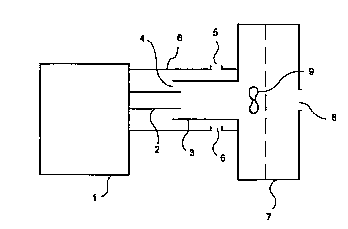
Figure 1 shows a schematic of a passive
15 catalytically stabilized thermal reaction system for
r~ rt~n of pollutants from a single cylinder,
small gasoline engine.
Figure 2 is a side view of a swirler means for
mixing gases for combustion.
~r~ TT~n I~D~:KI~-lun OF TEE
I hy~ AND ~ rC~ I 4~ 1TMI ~
The present invention is further described in
connection with the drawing . As shown in f igure l,
in one preferred ';- ~ the exhaust from a small
25 ~ACOl ;n~ engine l pas6es through exhaust line 2,
which serves as an air inductor nozzle, into line 3

2t ~6346
Wo 96123133 PCrlUS95/16836
thereby entraining air through opening 4 in line 3
and through openings 5 in shroud 6. The exhaust gas
and the mixed-in added air pass from line 3 into
muffler 7. Gases exiting muffler,7 pass through
5 vent opQn;nqC 8. Advant~Qo~lcly the gases may enter
muffler 7 into contact with a swirler 9 to promote
mixing and thus reaction of fuel values. A swirler
may also be employed to create a low ~JLe~ ULe region
near the muffler inlet and thus inhibit backflow of
10 gases through the open end of line 3. Swirler g
functions as a means for in~ in~ effective
recirculation of gases flowing through the muffler
7. A more complete mixing of the gases occurs with
creation of swirling ~ULLell~Si in the muffler 7.
15 ~igure 2 is a side view of a reyL~..LQLive swirler
9 and shows a spiral arr~-, L of vanes 10 whereby
the energy of entering gases is used to induce a
rolling motion within the gases L~ ;n;n~ in muffler
7 . The vanes 10 of swirler 9 cause the ; r ; n~
20 gases to enter muffler 7 in a turbulent flow,
causing a portion of the entering gases to reverse
the direction of their flow. Other means of
creating recirculation of gases in the muffler 7
will be reco~n; ~Qrl by those skilled in the art.
25 Typically, engine operation is sufficiently rich to
allow gas phase thermal combustion of the exhaust

21 86346
Wo 96/23133 pcrNsssll6836
.
gas fuel values. In this case at least portions of
the muffler 7 internal wall surface6 are coated with
a noble metal catalyst, preferably a platinum metal,
to ignite and stAh; 1 i 7e combustion thus permitting
5 ~f f i iPnt combustion of the fuel values over a wide
range of operating conditions. This results in very
low P~ isn~ of cA ~ c e.,uc pollutants .
Shroud 6 DULLU~ S opening 4 in line 3 serving
as a sound shield to muffle exhaust pulse noise
lO emanating from opening 4 and to permit ducting air
from an engine or muffler air cooling jacket to
further minimize escape of sound. Shroud 6 also
serves to contain any back flow leakage from line 3.
l~T.l~! ~
Fuel rich exhaust gas from a small Briggs and
5~La~UIl single cylinder g~ nP powered spark
ignition engine having a displ~ ~ of less than
about 400 cc driving an electrical generator was
20 passed through an exhaust pipe of conventional size
discharging as an injector nozzle into a larger pipe
and inducting air through the opening between the
discharge nozzle and the outer pipe. The eYhaust
gases with entrained air were passed to a
25 conventional Briggs and Stratton Super Lo-~o~e
muffler (Part No. 490,547) which had been modified

21 86346
Wo 96r23133 PCr/US95/16836
by the addition of a coating of a platinum catalyst
to the internal baffle plate surfaces to ignite and
stabilize thermal rP~cti~nc in the ~uffler and by
addition of fixed swirler vanes opposite the
5 muffler inlet. Thermal reaction of the fuel values
in the exhaust gases with the oxygen in the
inducted air resulted in low exhaust ~r,i~:cjnnF: over
the full operating range from idle to full load as
shown in the following table.
Exit Temp. HC,ppm* C0,~
idle 825 K 40 0 . 2
1/4 load 858 K 10 0 . 2
1/2 load 903 K 3 0.15
3/4 load 945 K 1 0 . 2
15 full load 993 K 0 0 . 3
~as measured by NDIR automotive analyser
In L.UII-LC-SL to a conventional mass transfer
limited catalytic converter, conversion of carbon
L. i nPd essentially constant over a wide
20 range of exhaust flows and conversion of
hydro~rhnnc actually increased with increase in
flow. Typical u--~ LLolled emissions levels for
this engine were 370 ppm hydrocarbons and 4 . 9
percent carbon tlP at idle, 340 ppm
25 hydrocarbons and 6.2 percent carbon ~r ~P at half
.
-

2 1 8 6 3 4 6 ~
Wo 96123133 PCr/US95116836
load, and 320 ppm hydrocarbons and 7 . 8 percentcarbon ~r; d~ at full load.

Representative Drawing
A single figure which represents the drawing illustrating the invention.
Administrative Status

2024-08-01:As part of the Next Generation Patents (NGP) transition, the Canadian Patents Database (CPD) now contains a more detailed Event History, which replicates the Event Log of our new back-office solution.

Please note that "Inactive:" events refers to events no longer in use in our new back-office solution.

For a clearer understanding of the status of the application/patent presented on this page, the site Disclaimer , as well as the definitions for Patent , Event History , Maintenance Fee  and Payment History  should be consulted.

Event History

Description Date
Inactive: IPC expired 2010-01-01
Inactive: IPC removed 2009-12-18
Inactive: IPC from MCD 2006-03-12
Time Limit for Reversal Expired 2003-12-22
Application Not Reinstated by Deadline 2003-12-22
Deemed Abandoned - Failure to Respond to Maintenance Fee Notice 2002-12-23
Inactive: Abandon-RFE+Late fee unpaid-Correspondence sent 2002-12-23
Letter Sent 1999-02-01
Reinstatement Requirements Deemed Compliant for All Abandonment Reasons 1999-01-21
Deemed Abandoned - Failure to Respond to Maintenance Fee Notice 1998-12-21
Letter Sent 1998-09-08
Reinstatement Requirements Deemed Compliant for All Abandonment Reasons 1998-09-01
Deemed Abandoned - Failure to Respond to Maintenance Fee Notice 1997-12-22
Application Published (Open to Public Inspection) 1996-08-01

Abandonment History

Abandonment Date Reason Reinstatement Date
2002-12-23
1998-12-21
1997-12-22

Maintenance Fee

The last payment was received on 2001-12-21

Note : If the full payment has not been received on or before the date indicated, a further fee may be required which may be one of the following

  • the reinstatement fee;
  • the late payment fee; or
  • additional fee to reverse deemed expiry.

Patent fees are adjusted on the 1st of January every year. The amounts above are the current amounts if received by December 31 of the current year.
Please refer to the CIPO Patent Fees web page to see all current fee amounts.

Fee History

Fee Type Anniversary Year Due Date Paid Date
MF (application, 2nd anniv.) - small 02 1997-12-22 1998-09-01
Reinstatement 1998-09-01
MF (application, 3rd anniv.) - small 03 1998-12-21 1999-01-21
Reinstatement 1999-01-21
MF (application, 4th anniv.) - small 04 1999-12-21 1999-12-13
MF (application, 5th anniv.) - small 05 2000-12-21 2000-12-20
MF (application, 6th anniv.) - small 06 2001-12-21 2001-12-21
Owners on Record

Note: Records showing the ownership history in alphabetical order.

Current Owners on Record
WILLIAM C. PFEFFERLE
Past Owners on Record
None
Past Owners that do not appear in the "Owners on Record" listing will appear in other documentation within the application.
Documents

To view selected files, please enter reCAPTCHA code :


To view images, click a link in the Document Description column. To download the documents, select one or more checkboxes in the first column and then click the "Download Selected in PDF format (Zip Archive)" or the "Download Selected as Single PDF" button.

List of published and non-published patent-specific documents on the CPD .

If you have any difficulty accessing content, you can call the Client Service Centre at 1-866-997-1936 or send them an e-mail at CIPO Client Service Centre.


Document
Description 
Date
(yyyy-mm-dd) 
Number of pages   Size of Image (KB) 
Representative drawing 1997-10-26 1 3
Abstract 1996-07-31 1 34
Description 1996-07-31 10 261
Claims 1996-07-31 3 58
Drawings 1996-07-31 1 6
Reminder of maintenance fee due 1997-08-23 1 111
Courtesy - Abandonment Letter (Maintenance Fee) 1998-02-01 1 187
Notice of Reinstatement 1998-09-07 1 172
Courtesy - Abandonment Letter (Maintenance Fee) 1999-01-17 1 184
Notice of Reinstatement 1999-01-31 1 170
Reminder - Request for Examination 2002-08-21 1 115
Courtesy - Abandonment Letter (Maintenance Fee) 2003-01-19 1 176
Courtesy - Abandonment Letter (Request for Examination) 2003-03-02 1 167
Fees 1999-12-12 1 41
Fees 2000-12-19 1 33
Fees 1999-01-20 1 47
Fees 1998-08-31 1 52
Fees 2001-12-20 1 31
International preliminary examination report 1996-09-23 1 35