Language selection

Search

Patent 2186473 Summary

Third-party information liability

Some of the information on this Web page has been provided by external sources. The Government of Canada is not responsible for the accuracy, reliability or currency of the information supplied by external sources. Users wishing to rely upon this information should consult directly with the source of the information. Content provided by external sources is not subject to official languages, privacy and accessibility requirements.

Claims and Abstract availability

Any discrepancies in the text and image of the Claims and Abstract are due to differing posting times. Text of the Claims and Abstract are posted:

  • At the time the application is open to public inspection;
  • At the time of issue of the patent (grant).
(12) Patent Application: (11) CA 2186473
(54) English Title: GAS SPRING ARRANGEMENT
(54) French Title: DISPOSITIF POUR RESSORT PNEUMATIQUE
Status: Deemed Abandoned and Beyond the Period of Reinstatement - Pending Response to Notice of Disregarded Communication
Bibliographic Data
(51) International Patent Classification (IPC):
  • F16F 09/48 (2006.01)
  • F16F 09/02 (2006.01)
  • F16F 09/36 (2006.01)
(72) Inventors :
  • SAND, GUNNAR (Sweden)
  • GUSTAFSSON, KRISTER (Sweden)
(73) Owners :
  • STROMSHOLMENS MEKANISKA VERKSTAD AB
(71) Applicants :
  • STROMSHOLMENS MEKANISKA VERKSTAD AB (Sweden)
(74) Agent: LAVERY, DE BILLY, LLP
(74) Associate agent:
(45) Issued:
(86) PCT Filing Date: 1995-02-09
(87) Open to Public Inspection: 1995-10-12
Availability of licence: N/A
Dedicated to the Public: N/A
(25) Language of filing: English

Patent Cooperation Treaty (PCT): Yes
(86) PCT Filing Number: PCT/SE1995/000129
(87) International Publication Number: SE1995000129
(85) National Entry: 1996-09-25

(30) Application Priority Data:
Application No. Country/Territory Date
9401119-4 (Sweden) 1994-03-31

Abstracts

English Abstract


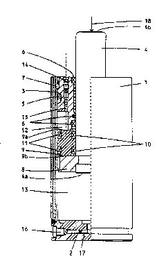
The invention relates to an arrangement for a gas spring. The
arrangement comprises a cylinder (1). At its one end, this is delimited by a
fixed end wall (2), and at its other end there is a first guide (3) sealed against
the inner wall of the cylinder (1) and against a piston rod (4) capable of axialmovement within the cylinder (1). The piston rod (4) has a second guide (8)
mounted in such a way as to be capable of sliding against the inner wall. An
annular piston (9) sealed against the inner wall and against the piston rod (4)
is mounted on the piston rod (4) between the guides (3; 8) in such a way
that it is free to slide. This divides the inner space of the cylinder (1) into a
first and a second part space (12; 13). In an initial position, in which the gasspring is unaffected, there is present in the first part space (12) a pressure
which is greater than the pressure present in the second part space (13). The
annular piston (9) is retained between the guides (3, 8) through the effect of
the pressure acting upon, on the one hand, one surface (9a) of the annular
piston (9) and, on the other hand, the other surface (9b) of the annular piston
(9) and the end surface (4a) of the piston rod (4).


French Abstract

L'invention concerne un dispositif conçu pour un ressort pneumatique. Ce dispositif comporte un cylindre (1) délimité à une de ses extrémités par une paroi d'extrémité fixe (2) et, à son autre extrémité, se trouve un premier guide (3) scellé contre la paroi intérieure dudit cylindre (1) et contre une tige de piston (4) pouvant effectuer un déplacement axial à l'intérieur du cylindre (1). La tige de piston (4) possède un deuxième guide (8) monté de manière à pouvoir coulisser contre la paroi intérieure. Un piston annulaire (9) scellé contre la paroi intérieure et contre la tige de piston (4) est monté sur ladite tige de piston (4) entre les guides (3, 8) de façon à pouvoir coulisser librement. Ceci divise l'espace intérieur du cylindre (1) en un premier et en un deuxième espace partiel (12, 13). En position initiale de non-actionnement du ressort pneumatique, une pression dans le premier espace partiel (12) est supérieure à la pression présente dans le deuxième espace partiel (13). Le piston annulaire (9) est retenu entre les guides (3, 8) sous l'effet de la pression s'exerçant, d'une part, sur une surface (9a) du piston annulaire (9) et, d'autre part, sur l'autre surface (9b) du piston annulaire (9) et sur la surface d'extrémité (4a) de la tige de piston (4).

Claims

Note: Claims are shown in the official language in which they were submitted.

Claims
1. Arrangement for a gas spring comprising a cylinder (1), which at
its one end is delimited by a fixed end wall (2), and which at its
other end has a first guide (3) sealed against the inner wall of
the cylinder (1) and against a piston rod (4) capable of axial
movement within the cylinder (1), in conjunction with which the
end of the piston rod (4) facing towards the end wall (2) is
executed with a second guide (8) mounted in such a way as to be
capable of sliding against said inner wall, characterized in that
an annular piston (9) sealed against the aforementioned inner wall
and against the piston rod (4) is mounted on the piston rod (4)
between the aforementioned guides (3; 8) in such a way that it
is free to slide, which annular piston divides the inner space of
the cylinder (1) between the aforementioned first guide (3) and
the end wall (2) into a first part space (12) delimited by the
first guide (3) and the annular piston (9) and into a second part
space (13) delimited by the annular piston (9) and the end wall
(2), in that in an initial position, in which the gas spring is
unaffected, there is present in the first part space (12) a
pressure which is greater than the pressure present in the second
part space (13), such that the annular piston (9) is retained
between the aforementioned guides (3; 8) through the effect of the
pressure acting upon, on the one hand, one surface (9a) of the
annular piston (9) and, on the other hand, the other surface (9b)
of the annular piston (9) and end surface (4a) of the piston rod.
2. Arrangement in accordance with Patent Claim 1, characterized in
that the second part space (13) communicates with a pressure
source, the pressure of which is so arranged as to vary in a
predetermined fashion with the position of the piston rod in the
gas spring.
3. Arrangement in accordance with one or other of the foregoing
Patent Claims, characterized in that a damping body (19) made of
an elastic material is introduced between the annular piston (9)
and the first guide (3) (alternatively, the second guide).

Description

Note: Descriptions are shown in the official language in which they were submitted.


~o 95/271~7 2 l 8 6 4 ~ 3 I'~,lI tl!" ~ ,7
~AC sDrin~ arrangement
The present invention relates to an a~, , L for a gas spring
comprising a cylinder, which at its one end is delimited by a fixed end
wall, and at its other end has a first guide sealed against the inner
h.i'l of the cylinder and against a piston rod capable of axial movement
5 within the cylinder, in conjunction with which the end of the piston rod
facing towards the end wall is executed with a second guide mounted in
such a way as to be capable of sliding against said inner wall.
A conventional gas spring operates in a similar manner to a helical
10 spring, i.e it produces a spring resistance equivalent to the compression
from the moment at which it is affected by a force.
In many applications this force is represented by a moving part of a
machine, the movement of which requires to be contained and damped.
15 Because of metal components which strike one another with full force,
this gives rise to disturbing mechanical noise and din, which cannot be
accepted under current working environment legislation. Attempts have
been made to dampen the contact between the moving part of the machine
and the gas spring with the help of helical springs or damping elements
20 made of an elastic material. These attempts were not particularly
successful, since helical springs do not give the desired effect, and the
stresses on such damping elements are considerable and the service life
of the elements is accordingly very limited. Both the purchase and
replacement of damping elements also involve truly daunting costs.
Z5
The object of the present invention is to eliminate the aforementioned
disadvantages and to bring about an acceptable noise level having regard
for working environment legislation. This is achieved in accordance with
the invention in that an annular piston sealed against the aforementioned
30 inner wall and against the piston rod is mounted on the piston rod
betwee~ the aforementioned guides in such a way that it is free to slide,
which annular piston divides the inner space of the cylinder between the
aforementioned first guide and the end wall into a first part space
delimited by the first guide and the annular piston and into a second
35 part space delimited by the annular piston and the end wall, in that, in
.. . . .. . . . . .

W095/27157 2 ~ A 2 1 8 6 4 7 3 r~ s
an initial position in which the gas ~ spring is unaffected, there is
present in the first part space a pressure which is greater than the
pressure present in the second part space, such that the annular piston
is reta~ned between the aforementioned guides through the effect of the
5 pressure acting upon, on the one hand, one surface of the annular piston
and, on the other hand, the other surface of the annular piston and the
end surface of the piston rod. ~his means that, when the piston rod is
actuated by an external increasing force acting in an axial sense to the
end walr of the cylinder, which causes the piston rod to be inserted
10 gradually into the cylinder, in conjunction with which from the initial
pos~tion, in which the spring force of the gas spring is negligible, to
a first position of the piston rod, in which the pressures in the two
part spaces are identical, the pressure in the second part space
gradually d,u,u~ the pressure prevailing in the second part space,
15 the spring force of the gas spring remains negligible compared with the
spring force prevailing after passing the aforementioned first piston rod
position, and so that, as the force acting upon the piston rod reduces,
after passing the aforementioned first piston rod position, the spring
force is once more a fraction of the spring force that was present prior
20 to passing the first piston rod position, only to become negligible once
more in the initial position.
What is achieved through the characterist~cs of the invention is that the
spring force is negligible at the moment when mechanical contact occurs
25 _ between the part of the machine and the gas spring; only after mechanical
contact has been established does the gas spring produce a spring force
proportional to the compresslon, which reduces the noise level.
Further characteristics and advantages of the invention can be seen from
30 the a~ g sub-claims an~i the following description, with reference
to the accompinying drawings, which illustrate a gas spring in accordance
with the invention in longitudinal section.
Figure 1 accordingly shows the piston rod of the gas spring in an initial
35 positlon, Figure 2 shows the piston rod in a first position, and Figure
3 shows the piston rod in an end position. figure 4 shows a gas spring
with a damping body made of an elastic material.
....... .. _ _ _ _ _ _ .. _ _ . _ . , .

~ w0 9~/27157 3 2 1 8 6 4 / s
The designation I is used in the drawings in respect of a cylinder, which
at lts one end i5 delimited by a fixed end wall 2, and which at its other
end has a guide 3 for a piston rod 4 capable of axial movement within the
cylinder. The guide 3 is sealed against the inner wall of the cylindér
5 1 by means of a static rlng seal 5 and against the piston rod 4 by means
of sealing rings 6, and is fixed relative to the cylinder I by means of
a 10cking ring 7. At the end of the piston rod 4 facing towards the end
wall 2, the piston rod 4 is executed with a guide 8 mounted in such a way
as to be capable of sliding against the in~er wall of the cylinder, which
guide is not sealed against the cylinder wall; the piston rod 4 thus
operates as a plunger piston.
In accordance with the lnvent10n, an annular piston 9 is mounted in such
a way that lt is capable of sliding between the guides 3 and 8 on the
piston rod 4, which annular piston is sealed against the plston rod 4 and
the inner wall of the cylinder 1 by means of annular seals 10 and 11,
thereby dividing the inner space of the cylinder I between the end wall
2 and the guide 3 into two part spaces 12 and 13. A channel 15 through
the guide 3 executed with a valve connection 14 discharges into part
space 12, and a channel 17 through the end wall 2 with a valYe connection
16 similarly discharges into part space 13.
Gas has been introduced into the part spaces via the valve connections
14 and 16, so that in an initial position illustrated in Figure 1, the
pressure prevailing inside part space 12 is higher than the pressure
prevailing inside part space 13. Because the pressure in part space 12
only acts on one surface 9a of the annular piston 9, whereas the pressure
in part space 13 acts on the other surface 9b of the annular piston 9 and
on the end surface 4a of the piston rod 4, it is possible to select the
aforementioned pressures in such a way that the annular piston 9 is held
securely between the guides 3 and 8.
If an axial force, indicated in the drawing by an arrow 18, is applied
to the outer end surface 4a of the piston rod 4, the following will
35 occur: due to the aforementioned pressure conditions, the gas spring
exhibits negligible spring force in the i~itial position. As the piston
rod 4 moves into the cylinder, the gas pressure in part space 13 rises,

CA21 86473
. ~ .
wo ss/27157 ~ 4 ~ 5 ~
and the gas pressure in part space 12 falls. In the position illustrated
in Figure Z, the pressures in part spaces 12 and 13 are assumed to be
equal, and the annular piston 9 is thus able to slide freely on the
p,ston rod 4. If the piston rod is now introduced even further into the
5 cylinder, the gas spring will produce a spring force equivalent to the
co.~ression until the end position illustrated in Fig. 3 is finally
rea~hed.
When the force designatea by the arrow 18 is reduced to zero, the process
10 described above will occur in the reverse sequence.
According to one particular characteristic, the part space 13 is causedto communicate with a pressure source not shown in the drawing, the
pressure of which is so arranged as to vary in a predetermined fashion
15 with the position of the piston rod in the gas spring. A person skilled
1n the art will appreciate that this requires a sensor sensitive to the
position of the piston rod, the output signal from which sensor is able
to affect the pressure source in such a way that the desired pressure
sequence i s ach i eved .
According to another particular characteristic of the invention, there
~s present between the annular piston 9 and one or other of the guides
3 or 8 a damping body l9 m?de of an elastic material. The job of the
damping body l9 is to further damp any residual noise.
ZZ
'' ';'.'`, '' ;
..

Representative Drawing
A single figure which represents the drawing illustrating the invention.
Administrative Status

2024-08-01:As part of the Next Generation Patents (NGP) transition, the Canadian Patents Database (CPD) now contains a more detailed Event History, which replicates the Event Log of our new back-office solution.

Please note that "Inactive:" events refers to events no longer in use in our new back-office solution.

For a clearer understanding of the status of the application/patent presented on this page, the site Disclaimer , as well as the definitions for Patent , Event History , Maintenance Fee  and Payment History  should be consulted.

Event History

Description Date
Inactive: IPC from MCD 2006-03-12
Time Limit for Reversal Expired 1998-02-09
Application Not Reinstated by Deadline 1998-02-09
Deemed Abandoned - Failure to Respond to Maintenance Fee Notice 1997-02-10
Application Published (Open to Public Inspection) 1995-10-12

Abandonment History

Abandonment Date Reason Reinstatement Date
1997-02-10
Owners on Record

Note: Records showing the ownership history in alphabetical order.

Current Owners on Record
STROMSHOLMENS MEKANISKA VERKSTAD AB
Past Owners on Record
GUNNAR SAND
KRISTER GUSTAFSSON
Past Owners that do not appear in the "Owners on Record" listing will appear in other documentation within the application.
Documents

To view selected files, please enter reCAPTCHA code :


To view images, click a link in the Document Description column. To download the documents, select one or more checkboxes in the first column and then click the "Download Selected in PDF format (Zip Archive)" or the "Download Selected as Single PDF" button.

List of published and non-published patent-specific documents on the CPD .

If you have any difficulty accessing content, you can call the Client Service Centre at 1-866-997-1936 or send them an e-mail at CIPO Client Service Centre.


Document
Description 
Date
(yyyy-mm-dd) 
Number of pages   Size of Image (KB) 
Abstract 1995-10-11 1 54
Description 1995-10-11 4 192
Claims 1995-10-11 1 47
Drawings 1995-10-11 4 68
Representative drawing 1997-10-28 1 9
International preliminary examination report 1996-09-24 19 720