Language selection

Search

Patent 2186659 Summary

Third-party information liability

Some of the information on this Web page has been provided by external sources. The Government of Canada is not responsible for the accuracy, reliability or currency of the information supplied by external sources. Users wishing to rely upon this information should consult directly with the source of the information. Content provided by external sources is not subject to official languages, privacy and accessibility requirements.

Claims and Abstract availability

Any discrepancies in the text and image of the Claims and Abstract are due to differing posting times. Text of the Claims and Abstract are posted:

  • At the time the application is open to public inspection;
  • At the time of issue of the patent (grant).
(12) Patent: (11) CA 2186659
(54) English Title: MASKING CYLINDER BORE EXTREMITIES FROM INTERNAL THERMAL SPRAYING
(54) French Title: METHODE D'OBTURATION DES EXTREMITES DES CYLINDRES DESTINES A ETRE TRAITES PAR PROJECTION THERMIQUE
Status: Term Expired - Post Grant Beyond Limit
Bibliographic Data
(51) International Patent Classification (IPC):
  • C23C 4/02 (2006.01)
  • B05B 12/20 (2018.01)
  • B05B 13/06 (2006.01)
(72) Inventors :
  • DONOVAN, DAVID A. (United States of America)
(73) Owners :
  • FORD MOTOR COMPANY OF CANADA, LIMITED
  • FORD MOTOR COMPANY OF CANADA, LIMITED
(71) Applicants :
  • FORD MOTOR COMPANY OF CANADA, LIMITED (Canada)
  • FORD MOTOR COMPANY OF CANADA, LIMITED (Canada)
(74) Agent: MARKS & CLERK
(74) Associate agent:
(45) Issued: 2007-09-25
(22) Filed Date: 1996-09-27
(41) Open to Public Inspection: 1997-05-01
Examination requested: 2003-09-15
Availability of licence: N/A
Dedicated to the Public: N/A
(25) Language of filing: English

Patent Cooperation Treaty (PCT): No

(30) Application Priority Data:
Application No. Country/Territory Date
08/550,475 (United States of America) 1995-10-30

Abstracts

English Abstract

Method of masking one or more extremities of a cylinder bore from internal thermal spraying, when using a rotary gun inserted from one end of the bore, by essentially the steps of: (a) supporting one or more inflatable mask members adjacent an end of the bore wall; (b) pressurizing the inflatable mask member to expand and annularly engage an end of the bore, the mask being constituted of an inflatable and collapsible air tight bag of heat resistant (fiberglass) cloth coated on opposite sides with a sacrificial heat resistant non-stick coating (silicone). The inflatable characteristic of the mask member allows it to conform to the periphery of the cylinder bore extremities, and allows it to be easily installed in or through the component in its deflated condition. The mask is reusable by being comprised of coating material that may gradually be sacrificed to heat and wear of the over spray.


French Abstract

La méthode d'obturation des extrémités des cylindres protège leur surface interne contre la projection thermique lorsqu'on insère un pistolet rotatif à l'une des extrémités. La méthode se déroule comme suit : (a) fixer un masque gonflable près de l'extrémité de l'ouverture; (b) gonfler le masque pour lui imprimer une pénétration annulaire dans l'ouverture, celui-ci étant fait d'un tissu étanche contractile résistant à la chaleur (fibre de verre), enduit de chaque côté d'un revêtement sacrificiel antiadhésif résistant à la chaleur (silicone). Le masque, en étant gonflable, s'adapte parfaitement à la courbure des extrémités du cylindre. Dégonflé, il est facile à mettre en place. Le masque peut être réutilisé, mais son revêtement sacrificiel disparaît lentement sous l'effet de la chaleur et de l'usure des pulvérisations répétées.

Claims

Note: Claims are shown in the official language in which they were submitted.

The embodiments of the invention in which an exclusive
property or privilege is claimed are defined as follows:
1. A method of masking cylinder bore extremities form
internal thermal spraying by use of a rotary gun inserted from one end of
the bore, the method comprising the steps of:
(a) supporting one or more inflatable mask member
adjacent an end of the bore wall; and
(b) pressurizing the inflatable mask member to expand and
annularly engage such end of the bore wall, said mask
member being constituted of an inflatable and
collapsible air tight bag of heat resistant cloth coated on
opposite sides with a sacrificial heat resistant non-stick
coating.
2. The method as in claim 1, in which said mask member
when inflated is doughnut shape effective to resiliently and sealingly
engage the annular extremity of the bore wall.
3. The method as in claim 1, in which said cloth is
comprised of fiberglass and said coating is comprised of silicone effective
to make the cloth air tight.
4. The method as in claim 1, in which said cylinder bore
wall is part of an engine block and said mask members are supported on
an elongated exhaust manifold tube extending through the block in the
space normally occupied by a crank shaft, said manifold tube having
opening in communication with the bores through the interior of said
doughnut shaped masked members.
-6-

5. The method as in claim 1, in which said mask member
is reusable for repetitive thermal spraying cycles, the coating exposed to
over spray of said spraying partially ablating or partially eroding away
with repeated use.
6. The method as in claim 1 which comprises (c)
supporting an annular flanged mask member on the gun that is inserted
into the cylinder bore wall, said flanged mask member being slideable
longitudinally along the gun to assure and retain closure with said one
end after the gun continues to move longitudinally within the bore wall.
7. The method as in claim 6, in which said flanged mask
member has a flange that is inflatable.
-7-

Description

Note: Descriptions are shown in the official language in which they were submitted.


~-- 2186659
MASKING CYLINDER BORE EXTREMITIES FROM
INTERNAL THERMAL SPRAYING
Background of the Invention
Technical Field
This invention relates to the technology of preventing over
spray of cavities of components and more particularly to masking
complex components containing such cavities when carrying out thermal
spraying within such cavities.
Discussion of the Prior Art
Thermal spraying of metal powder, droplets and other
comminuted particles onto interior cylinder bore surfaces of an
automotive engine block has become a significant fabrication technique
that forms a wear and anti-friction coating on such surfaces. Thermal
spraying, whether by wire arc, plasma or flame, will project the particles
in a relatively wide spray pattern at very high velocities from a gun
nozzle that is stationed relatively close to the bore surface due to the
restricted diameter of conventional cylinder bores (typically 4-6 inches).
The combination of such high velocity and short travel distance will allow
a small proportion of the particles to bounce or be deflected from the
target surface resulting in over spray. Such over spray contaminates
adjacent block surfaces not intended to be coated or such over spray
merely falls free of the block as waste material. The adjacent surfaces
may comprise the crankcase chamber and support surfaces for the
crankshaft.
Early masking techniques used resilient or ablatable plugs
to protect holes of components that are being thermally sprayed or
painted. The plugs needed to be essentially the same size as the opening
and needed to penetrate into the opening so that the resiliency of the
plug obtained closure and conformance to the hole. Such plugs are not
-1-

CA 02186659 2004-03-11
good for components having restricted access to the openings and are a
detriment
when the interior of the openings must not be penetrated or obscured to allow
for
proper spraying. Fixed templates of elastomor material have also been used to
cover broad planar surfaces to be protected during spraying or painting. These
templates are difficult to use when the component has a complex structure
preventing easy access. Gases have also been used as a masking medium; gases
are
blown across the interior side of a folded or curled sheet material to mask
such side
from a molten bath of metal into which the folded sheet is dipped. If such
technique were to be used with thermal spraying of internal cavities, such
gases
would interfere with the thermal spray deposition.
SUMMARY OF THE INVENTION
The present invention is directed towards the provision of a method of
masking components to permit thermal spraying of cavities in such component,
the
masking enabling one or more of the following: (i) removable access of the
spray-
head into and out of the cavity while covering the cavity at one or more of
its
extremities; (ii) installation on components having complex structure
surrounding
the cavity extremities; (iii) traverse of the spray-head along the full length
of the
cavity; (iv) resistance to the high temperature of molten metal particles; and
(v)
transfers and collects waste over-spray particles.
In accordance with one aspect of the present invention, there is provided a
method of masking one or more extremities of a cylinder bore from internal
thermal
spraying, when using a rotary gun inserted from one end of the bore,
comprising
the steps of (a) supporting one or more inflatable mask members adjacent an
end
of the bore wall; (b) pressurizing the inflatable mask member to expand and
annularly engage the end of the bore wall, the mask being constituted of an
inflatable and collapsible air tight bag of heat resistant (such as
fiberglass)
cloth coated on opposite sides with a sacrificial heat resistant non-stick
coating
(such as silicone).
-2-

2186659
The inflatable characteristic of the mask member allows it to
conform to the periphery of the cylinder bore extremities, and allows it to
be easily installed in or through the component in its deflated condition.
The mask is reusable by being comprised of coating material that may
gradually be sacrificed to heat and wear of the over spray. In a more
particular aspect of the invention, one set of inflatable mask members are
saddled and ganged on a vacuum exhaust conduit that fits into the
crankshaft spacing of the block allowing for ease of precise positioning of
a plurality of collapsed mask members ready for inflation with the
io conduit ready for collection of over-spray. Another mask member may be
saddled on the gun to ride therewith during cavity insertion to effect
closure of the other extremity.
BRIEF DESCRIPTION OF THE DRAWINGS
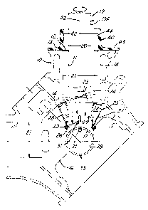
Figure 1 is a sectional elevational view of an internal
combustion engine block showing the mask members of this invention
installed to prevent over spray while a row of rotary guns carry out
thermal spraying of the interior of a bank cylinder bores;
Figure 2 is a sectional view taking substantially a long line
2-2 of figure 1; and
Figure 3 is an enlarged prospective view of one donut
shaped inflated mask member.
DETAILED DESCRIPTION IN BEST MODE
As shown in figure 1, a v-shaped aluminum block 10, of an
internal combustion engine, presents two rows or banks of cylinder bore
cavities 11. One extremity or lip 12 of each bore cavity opens on to a flat
deck 13 while the other extremity or lip 14 faces the crankcase chamber
15 of the block, such chamber being interrupted by several crankshaft
3o bearing walls 16 that present semi-circular bearing surfaces 17. The
block may also contain several other complex webs or walls, including
walls 18 providing cooling passages about the cylinder bore cavities.
-3-

2186659
The thermal spray gun 19 is carried on a barrel 19A that
has a diameter 20 smaller than the diameter 21 of the cylinder bore
cavity. The barrel 19A rotates about an axis 22 coincident with the axis
of the cylinder bore cavity. A spray nozzle 23 is directed radially across
the axis of the bore and is fed with primary and/or secondary gases from
a gas supply line 24.
The lower end or extremity 14 of the cylinder bore cavity is
masked by use of an annular inflatable mask member 25. Such member
is comprised of a rigid cylindrical collar base 26, usually of temperature
resistant sheet metal, and a bag 27 of cloth that is folded over or looped
over and along the upper rim 28 of the collar base 26. The edges or cuffs
29 of the cloth bag are secured to opposite sides of the collar base by
fasteners 30 to effect an air tight seal and create a doughnut shaped form
when inflated to engage the annular extremity of the bore wall. The
inflated bag is hollow in its center to allow excess thermal spray to pass
and be evacuated therethrough. An air supply nozzle 31 is secured along
the interior of the collar base to extend into the bag interior 32 along
folded cuff of cloth. The cloth is comprised of fiberglass or other heat
resistant cloth and is coated on both sides with a heat resistant non-
sticking material, such as silicone in a thickness of about .04 inches. The
silicone coating on the exterior will gradually wear away by erosion or
burning from contact with splatter; such sacrificial coating allows the
inner coating to remain viable and promote air tightness of the bag.
The plurality of collar bases 26 are supported on an
elongated exhaust vacuum manifold tube 33. The collar bases are placed
at intervals 34 equal to the spacing of the cylinder bore cavities along the
bank of the block. An air supply line 35 extends along the manifold tube
33 and communicates with each of the nozzles 31 for selective inflation of
each mask member 25. A suitable air supply 36 is provided for line 35
3o and a suitable vacuum source 37 is provided for the manifold tube 33. A
cut-out opening 38 is made in the manifold tube for each collar base,
-4-

2186659
conforming to the footprint of each collar base as it intersects with the
manifold tube.
The upper end or extremity 13 of the cylinder bore cavity is
masked by a flanged sleeve 40 surrounding the gun 19. The flanged
sleeve is comprised of a sleeve portion 41 having an internal diameter 42
greater than the diameter 20 of the barrel 19A of the gun and comprised
of a flat flanged portion 43 adapted to fit flush against the deck 13 of the
block. The spacing 44 allows air to be admitted to the cavity for
facilitating an exhaust stream induced by the vacuum manifold tube to
io withdraw over spray particles. The flanged sleeve 40 is slideably
supported on the gun barrel 19A so that upon insertion of the gun to the
mouth of the cavity, the flanged sleeve will close off the upper extremity
of the cavity except for limited air admission and thereby protect the
block face from contamination. As the gun penetrates deep into the bore
cavity, the flanged sleeve remains in flush contact with block deck while
the gun slides there through. Alternatively, the flanged sleeve may be
constituted as an inflatable member if needed.
The method of this invention thus uses inflatable shapes
conforming to the periphery of the cylinder bore wall extremities; the
inflatable shapes are carried on an exhaust manifold tube for ease of
insertion and accuracy of positioning; the inflatable shapes are coated so
as to have a surface that is partial sacrificial for reusability; and the
upper bore wall extremities closed by fixed or inflatable shape that is
saddled on the spray gun.
While particular embodiments of the invention have been
illustrated and described, it will be obvious to those skilled in the art that
various changes and modifications may be made without departing from
the invention, and it is intended to cover in the appended claims all such
modifications and equivalents as fall within the true spirit and scope of
this invention.
-5-

Representative Drawing
A single figure which represents the drawing illustrating the invention.
Administrative Status

2024-08-01:As part of the Next Generation Patents (NGP) transition, the Canadian Patents Database (CPD) now contains a more detailed Event History, which replicates the Event Log of our new back-office solution.

Please note that "Inactive:" events refers to events no longer in use in our new back-office solution.

For a clearer understanding of the status of the application/patent presented on this page, the site Disclaimer , as well as the definitions for Patent , Event History , Maintenance Fee  and Payment History  should be consulted.

Event History

Description Date
Inactive: IPC deactivated 2021-11-13
Inactive: IPC assigned 2021-09-02
Inactive: IPC expired 2018-01-01
Inactive: Expired (new Act pat) 2016-09-27
Inactive: IPC expired 2016-01-01
Grant by Issuance 2007-09-25
Inactive: Cover page published 2007-09-24
Inactive: Final fee received 2007-07-06
Pre-grant 2007-07-06
Notice of Allowance is Issued 2007-01-09
Letter Sent 2007-01-09
Inactive: Approved for allowance (AFA) 2006-12-04
Inactive: IPC from MCD 2006-03-12
Amendment Received - Voluntary Amendment 2004-03-11
Inactive: Status info is complete as of Log entry date 2003-10-15
Letter Sent 2003-10-15
Inactive: Application prosecuted on TS as of Log entry date 2003-10-15
All Requirements for Examination Determined Compliant 2003-09-15
Request for Examination Requirements Determined Compliant 2003-09-15
Application Published (Open to Public Inspection) 1997-05-01

Abandonment History

There is no abandonment history.

Maintenance Fee

The last payment was received on 2006-09-13

Note : If the full payment has not been received on or before the date indicated, a further fee may be required which may be one of the following

  • the reinstatement fee;
  • the late payment fee; or
  • additional fee to reverse deemed expiry.

Please refer to the CIPO Patent Fees web page to see all current fee amounts.

Owners on Record

Note: Records showing the ownership history in alphabetical order.

Current Owners on Record
FORD MOTOR COMPANY OF CANADA, LIMITED
Past Owners on Record
DAVID A. DONOVAN
Past Owners that do not appear in the "Owners on Record" listing will appear in other documentation within the application.
Documents

To view selected files, please enter reCAPTCHA code :


To view images, click a link in the Document Description column. To download the documents, select one or more checkboxes in the first column and then click the "Download Selected in PDF format (Zip Archive)" or the "Download Selected as Single PDF" button.

List of published and non-published patent-specific documents on the CPD .

If you have any difficulty accessing content, you can call the Client Service Centre at 1-866-997-1936 or send them an e-mail at CIPO Client Service Centre.


Document
Description 
Date
(yyyy-mm-dd) 
Number of pages   Size of Image (KB) 
Representative drawing 1997-08-11 1 23
Cover Page 1998-07-08 1 15
Abstract 1996-09-27 1 26
Cover Page 1996-09-27 1 15
Description 1996-09-27 5 248
Claims 1996-09-27 2 53
Drawings 1996-09-27 2 64
Description 2004-03-11 5 249
Representative drawing 2006-12-04 1 10
Cover Page 2007-08-28 2 49
Reminder of maintenance fee due 1998-05-28 1 111
Reminder - Request for Examination 2003-05-28 1 113
Acknowledgement of Request for Examination 2003-10-15 1 173
Commissioner's Notice - Application Found Allowable 2007-01-09 1 161
Fees 2003-09-15 1 49
Fees 2002-09-13 1 57
Fees 2001-08-21 1 52
Fees 1998-09-01 1 57
Fees 2004-09-13 1 47
Fees 2005-09-13 1 52
Fees 2006-09-13 1 53
Correspondence 2007-07-06 1 54
Fees 2007-09-19 1 57